ICPS_170993109001
•Download as PPTX, PDF•
0 likes•58 views

MATHEMATICAL MODELLING AND ADJUSTMENT OF GOVERNOR CHARACTERISTICS

Recommended
More Related Content
What's hot
What's hot (20)
Similar to ICPS_170993109001
Similar to ICPS_170993109001 (20)
More from SACHIN CHAUHAN
Recently uploaded
Recently uploaded (20)
ICPS_170993109001
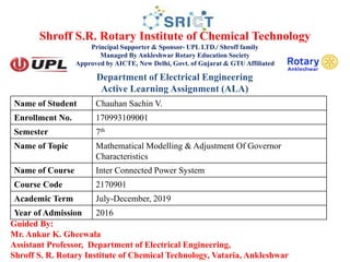
- 1. Shroff S.R. Rotary Institute of Chemical Technology Principal Supporter & Sponsor- UPL LTD./ Shroff family Managed By Ankleshwar Rotary Education Society Approved by AICTE, New Delhi, Govt. of Gujarat & GTU Affiliated Guided By: Mr. Ankur K. Gheewala Assistant Professor, Department of Electrical Engineering, Shroff S. R. Rotary Institute of Chemical Technology, Vataria, Ankleshwar Name of Student Chauhan Sachin V. Enrollment No. 170993109001 Semester 7th Name of Topic Mathematical Modelling & Adjustment Of Governor Characteristics Name of Course Inter Connected Power System Course Code 2170901 Academic Term July-December, 2019 Year of Admission 2016 Department of Electrical Engineering Active Learning Assignment (ALA)
- 2. • Mathematical Modeling • Adjustment Of Governor Characteristics 2 CONTENT
- 3. Model of Speed Governing System • Assume that the system is initially operating under steady conditions—the linkage mechanism stationary and pilot valve closed, steam valve opened by a definite magnitude, turbine running at constant speed with turbine power output balancing the generator load. Let the operating conditions be characterized by • We shall obtain a linear incremental model around these operating conditions. • Let the point A on the linkage mechanism be moved downwards by a small amount ΔyA. It is a command which causes the turbine power output to change and can therefore be written as 3
- 4. • where ΔPC is the commanded increase inpower. • The command signal ΔPC (i.e. ΔyE) sets into motion a sequence of events—the pilot valve moves upwards, high pressure oil flows on to the top of the main piston moving it downwards; the steam valve opening consequently increases, the turbine generator speed increases, i.e. the frequency goes up. Let us model these events mathematically. • Two factors contribute to the movement of C: 10/14/2018 4
- 5. • The movement ΔyD depending upon its sign opens one of the ports of the pilot valve admitting high pressure oil into the cylinder thereby moving the main piston and opening the steam valve by ΔyE. Certain justifiable simplifying assumptions, which can be made at this stage, are: • Inertial reaction forces of main piston and steam valve are negligible compared to the forces exerted on the piston by high pressure oil. • Because of (i) above, the rate of oil admitted to the cylinder is proportional to port openingΔyD. • The volume of oil admitted to the cylinder is thus proportional to the time integral of ΔyD,. The movement ΔyE is obtained by dividing the oil volume by the area of the cross-section of the piston. Thus • 5
- 6. • It can be verified from the schematic diagram that a positive movement ΔyD causes negative (upward) movement ΔyE accounting for the negative sign used in Eq. (8.4). • Taking the Laplace transform of Eqs. (8.2), (8.3) and (8.4), we get • Eliminating ΔYC(s) and ΔYD(s), we can write 6
- 7. • Where • Equation (8.8) is represented in the form of a block diagram in Fig. 8.3. • 7
- 8. Adjustment of Governor Characteristics • The control of system frequency and load depends upon the governor of the prime movers. • The below figure shows the characteristics of the speed governor system. 8
- 9. • For stable operation of generator ,the governors are designed to permitt the speed to drop as the load is increased . • Then slop of the curve represent the speed regulation R. • Governors typically have a speed regulation of 5-6% from zero to full load. 9
- 10. Where =Steady state speed at full load Nl =steady State Speed At No-load 10 FL If two or more alternators with droping govenor characteristics are connected to a power system there will be unique frequency at which they will share a load change. 0 =Rated speed
- 11. • Assme ,two generator units with droping characteristics as shown in above figure. • Let the initial frequency of both the unit is f with power output P1 and P2 when a load increases to P it causes the units to slow down/. • The governor increases the output until they reach a new common operating frequency f. 11
- 12. 12