SlideShare a Scribd company logo
1 of 148
R.M.K COLLEGE OF ENGINEERING
AND TECHNOLOGY
R.S.M NAGAR, PUDUVOYAL – 601 206
DEPARTMENT OF MECHANICAL ENGINEERING
FOURTH SEMESTER
ME2257 – COMPUTER
AIDED MACHINE
DRAWING LAB
DEPARTMENT OF MECHANICAL ENGINEERING
Computer Aided Machine Drawing Lab Manual By Ashok Kumar. R (AP / MECH) 2
ME2257 – COMPUTER AIDED MACHINE DRAWING
OBSERVATION NOTE BOOK
DEPARTMENT OF MECHANICAL ENGINEERING
Computer Aided Machine Drawing Lab Manual By Ashok Kumar. R (AP / MECH) 3
IV SEM MECHANICAL ENGINEERING
ME2257 – COMPUTER AIDED MACHINE DRAWING LAB
LIST OF EXERCISES
I) STUDY OF DRAWING STANDARDS & ASSEMBLY DRAWING
1) Study of Drawing Standards
2) Study of Welding Symbols
3) Study of Riveted Joints
4) Study of Keys
5) Study of Screw Threads and Threaded Fasteners
6) Study of Limits, Tolerance and Fits
7) Study of Assembly Drawings
II) ASSEMBLY DRAWING
8) Assembly Drawing of Muff Coupling in 2D
9) Assembly Drawing of Half Lap Muff Coupling in 2D
10) Assembly Drawing of Split Muff Coupling in 2D
11) Assembly Drawing of Unprotected Flange Coupling in 2D
12) Assembly Drawing of Protected Flange Coupling in 2D
13) Assembly Drawing of Universal Coupling in 2D
14) Assembly Drawing of Knuckle Joint in 2D
DEPARTMENT OF MECHANICAL ENGINEERING
Computer Aided Machine Drawing Lab Manual By Ashok Kumar. R (AP / MECH) 4
15) Assembly Drawing of Screw Jack in 2D
16) Assembly Drawing of Stuffing Box in 2D
17) Assembly Drawing of Plummer Block in 2D
18) Assembly Drawing of Connecting Rod in 2D
19) Assembly Drawing of Non Return Valve in 2D
20) Assembly Drawing of Safety Valve in 2D
21) Assembly Drawing Of Machine Vice in 2D
22) Assembly Drawing Of Tail Stock in 2D
III) ADDITIONAL CONTENT BEYOND THE SYLLABUS
23) AUDI car model in 2D
24) BMW car model in 2D
DEPARTMENT OF MECHANICAL ENGINEERING
Computer Aided Machine Drawing Lab Manual By Ashok Kumar. R (AP / MECH) 5
IV SEM MECHANICAL ENGINEERING
ME2257 – COMPUTER AIDED MACHINE DRAWING LAB
SYLLABUS
DRAWING STANDARDS
Code of practice for Engineering Drawing, BIS specifications – Welding symbols,
rivetedjoints, keys, fasteners – Reference to hand book for the selection of standard
components like bolts, nuts, screws, keys etc.
2-D DRAWINGS
Limits, Fits – Tolerancing of individual dimensions- Specification of Fits- Manual
Preparation of production drawings and reading of part and assembly drawings.
CAD PRACTICE (USING APPLICATION PACKAGES)
Drawing, Editing, Dimensioning, Plotting Commands, Layering Concepts, Hatching,
Detailing, Assembly, basic principles of GD&T (geometric dimensioning &tolerancing)
ASSEMBLY DRAWING (MANUAL & USING APPLICATION PACKAGES)
Manual parts drawing and preparation of assembled views given part details for components
followed by practicing the same using CAD packages.
SUGGESTED ASSEMBLIES:
Shaft couplings – Plummer block – Screw jack- Lathe Tailstock – Universal Joint – Machine
Vice – Stuffing box – safetyValves – Non-return valves– Connecting rod –Piston and crank
shaft– Multi plate clutch – Preparationof Bill of materials and tolerance data sheet
DEPARTMENT OF MECHANICAL ENGINEERING
Computer Aided Machine Drawing Lab Manual By Ashok Kumar. R (AP / MECH) 6
INDEX
EXPT
NO
DATE NAME OF THE EXPERIMENT
PAGE
NO
SIGN
1)
2)
3)
4)
5)
6)
7)
8)
9)
10)
11)
12)
13)
14)
DEPARTMENT OF MECHANICAL ENGINEERING
Computer Aided Machine Drawing Lab Manual By Ashok Kumar. R (AP / MECH) 7
EXPT
NO
DATE NAME OF THE EXPERIMENT
PAGE
NO
SIGN
15)
16)
17)
18)
19)
20)
21)
22)
23)
24)
25)
Signature of Lab in Charge Signature of HOD
DEPARTMENT OF MECHANICAL ENGINEERING
Computer Aided Machine Drawing Lab Manual By Ashok Kumar. R (AP / MECH) 8
STUDY OF DRAWING STANDARDS
EXPT NO: 1 DATE:
AIM:
To study about the basic fundamentals of the drawing standards used in machine
drawing.
CODE OF PRACTICE FOR ENGINEERING DRAWING:
The representation of any matter by some sign or mark on the drawing is known as
convention or Code. These conventions are specified by Bureau of Indian Standards (BIS)
and are called BIS specifications.
ISO STANDARDS:
In the 21st
century, growing international engineering and technological developments,
technical collaboration between mutual countries, exchange and export of technologies and
globalization leading to the establishment of various Multi-National Companies (MNCs)
have necessitated the inter-nationalization of engineering drawing standards.
INTERNATIONAL STANDARDS ORGANIZATION (I.S.O), Geneva, Switzerland, have
formulated (1970) international standards for engineering drawing, for which our country
has also given the approval and accordingly modified the Indian Standards IS 696:1972.
B.I.S:
Indian Standards Institution (I.S.I) is renamed as Bureau of Indian Standards (B.I.S) in
1983.Engineering Drawing Committee (E.D.C) of B.I.S has adopted the I.S.O standards in
Toto for the various topics given in the following Table.
DEPARTMENT OF MECHANICAL ENGINEERING
Computer Aided Machine Drawing Lab Manual By Ashok Kumar. R (AP / MECH) 9
Sl.No BIS Codes Topics
1) IS: 9609 (Parts 0 & 1) – 2001 Technical product documentation – Lettering
2) IS: 10711 – 2001
Technical products documentation – size and
layout of drawing sheets
3) IS : 10713 – 1983 Scales for use on Technical Drawing
4) IS : 10714 – 1983 General Principles of Presentation
5) IS: 10714 (Part 20) – 2001 Lines
6) IS : 10715 – 1983 Presentation of threaded parts on technical
drawing
7) IS : 10716 – 1983 Rules for presentation of springs
8) IS : 10717 – 1983 conventional representation of gears on
technical drawing
9) IS : 11663 – 1986 Conventional representation of common
features
10) IS : 11664 – 1986 Folding of drawing prints
11) IS : 11665 – 1986 Technical drawing – Title blocks 
12) IS : 11669 – 1986 Dimensioning on Technical Drawings
13) IS : 11670 – 1986 Abbreviation’s for use in Technical Drawing
14) IS: 15021 (Parts 1-4) – 2001 Technical Drawings – Projection Methods
15) IS: 7008 – 1988 Acme or Trapezoidal thread
16)
IS 4218 – 1976
IS 11698 – 1986
Metric screw threads
17) IS: 2292 – 1974 Taper keys
18) IS: 2293 – 1974 Gib – head keys
19) IS: 2048 – 1983 Feather keys
20) IS: 2294 – 1986 Woodruff keys
21) IS: 2327 – 1991 Spline shafts
22) IS 919 – 1963 Limits & Fits for engineering
DEPARTMENT OF MECHANICAL ENGINEERING
Computer Aided Machine Drawing Lab Manual By Ashok Kumar. R (AP / MECH) 10
RESULT:
Thus the basic fundamentals of the drawing standards used in machine drawing was
studied.
DEPARTMENT OF MECHANICAL ENGINEERING
Computer Aided Machine Drawing Lab Manual By Ashok Kumar. R (AP / MECH) 11
BASIC WELD SYMBOLS
S.NO FORM OF WELD DIAGRAM SYMBOL
1) FILLET
2) SQUARE BUTT
3) SINGLE – V BUTT
4) DOUBLE – V BUTT
5) SINGLE – U BUTT
6) DOUBLE – U BUTT
7) SINGLE – BEVEL BUTT
8) DOUBLE – BEVEL BUTT
9) SINGLE – J BUTT
10) DOUBEL – J BUTT
11) EDGE
12) SPOT
DEPARTMENT OF MECHANICAL ENGINEERING
Computer Aided Machine Drawing Lab Manual By Ashok Kumar. R (AP / MECH) 12
STUDY OF WELDING SYMBOLS
EXPT NO: 2 DATE:
AIM:
To study about the welding symbols.
WELDING:
It is a technique of making permanent joint. It is the process of joining two parts of
metal by fusing them together.
TYPES OF WELDING:
 Pressure welding or Forge welding
 Forge welding
 Thermit pressure welding
 Pressure gas welding
 Electric resistance welding
 Fusion welding
 Gas welding
 Electric arc welding
 Thermit fusion welding
 Fusion pressure welding
 Spot welding
 Seam welding
 Flash butt welding
DEPARTMENT OF MECHANICAL ENGINEERING
Computer Aided Machine Drawing Lab Manual By Ashok Kumar. R (AP / MECH) 13
DEPARTMENT OF MECHANICAL ENGINEERING
Computer Aided Machine Drawing Lab Manual By Ashok Kumar. R (AP / MECH) 14
TYPES OF WELD JOINTS:
 Butt joint
 Corner joint
 Tee joint
 Lap joint
 Edge joint
SYMBOLIC REPRESENTATION OF WELD:
Welded joints are symbolically represented as shown in figure.
 An arrow line pointing to the joint where the weld to be made.
 A dual reference line consisting of two parallel lines, one continuous and one
dashed.
 A basic symbol to specify the type of weld.
 A supplementary symbol to characterize the shape of the external surface on the
weld.
 Dimension of the weld.
ARROW LINE AND REFERENCE LINE:
The position of the arrow line with respect to the weld is of no special significance.
The side of the joint on which the arrow line is drawn is called “arrow side”. The side of the
joint remote to the arrow line is called “other side”. The reference line has significance on
the weld side. If the weld symbol is placed BELOW the reference line, the welding should
be done in the “ARROW SIDE”. If the weld symbol is placed ABOVE the reference line,
the welding should be done in the “OTHER SIDE”. If the weld symbol is placed both
DEPARTMENT OF MECHANICAL ENGINEERING
Computer Aided Machine Drawing Lab Manual By Ashok Kumar. R (AP / MECH) 15
EDGE PREPARATION
FORM OF
WELD
DIAGRAM
FORM OF
WELD
DIAGRAM
SQUARE BUTT SINGLE FILLET
SINGLE – V
BUTT
DOUBLE
FILLET
DOUBLE – V
BUTT
STRAIGHT
BEVEL
SINGLE – U
BUTT
SINGLE BEVEL
DOUBLE – U
BUTT
DOUBLE
BEVEL
SINGLE –
BEVEL BUTT
SINGLE J
BEVEL
DOUBLE –
BEVEL BUTT
DOUBLE J
BEVEL
SINGLE – J
BUTT
EDGE JOINT
DOUBEL – J
BUTT
CORNER JOINT
DEPARTMENT OF MECHANICAL ENGINEERING
Computer Aided Machine Drawing Lab Manual By Ashok Kumar. R (AP / MECH) 16
ABOVE and BELOW the reference line, the welding should be done in both the “ARROW
AND OTHER SIDES”.
EDGE PREPARATION:
The preparation of the edges of the pieces to be welded depends upon the thickness of
metal being welded Edge preparation is necessary when thickness increases so that heat
would be able to penetrate the entire depth. This ensures formation of sound welds. The edge
preparation is done by beveling the edges of the pieces after the rust, grease, oil or paint are
completely removed from their surfaces.
RESULT:
Thus the welding symbols were studied.
DEPARTMENT OF MECHANICAL ENGINEERING
Computer Aided Machine Drawing Lab Manual By Ashok Kumar. R (AP / MECH) 17
DEPARTMENT OF MECHANICAL ENGINEERING
Computer Aided Machine Drawing Lab Manual By Ashok Kumar. R (AP / MECH) 18
STUDY OF RIVETED JOINTS
EXPT NO: 3 DATE:
AIM:
To study about the riveted joints.
RIVET:
Rivets are short cylindrical pieces, made of mild steel or non – ferrous materials such
as copper, aluminum. A rivet consists of a head, cylindrical body or shank and a slightly
tapered tail.
If l = Length of the shank of the rivet
d = Diameter of rivet
t = Thickness of each of the connecting plates
RIVETING:
It is the process of forming a well – shaped concentric head from the projection
portion of the shank end of the rivet inserted in the holes previously drilled in the plates to be
fastened. The riveting process involves making of the holes in the plates and the formation
of the rivet head
CAULKING & FULLERING:
In boilers and hydraulic tanks containing pressurized fluids, there are possibilities of
leak at the joints between the two overlapping plates, or between the bearing plate and
underneath of the rivet head. Therefore the riveted joints of the boilers and tile hydraulic
tanks have to be made leak – proof. This is accomplished by burring down or forcing down
the edges of the rivet heads and the plates. This will force the edge of the plate or the rivet
head to bite into the bearing plate which makes the joint leak – proof.
DEPARTMENT OF MECHANICAL ENGINEERING
Computer Aided Machine Drawing Lab Manual By Ashok Kumar. R (AP / MECH) 19
DEPARTMENT OF MECHANICAL ENGINEERING
Computer Aided Machine Drawing Lab Manual By Ashok Kumar. R (AP / MECH) 20
The burring down of the edges of the rivet head or the plates is accomplished by
hammering down by a blunt chisel like tool of about 5mm thick and 50 mm in breadth with
the edge ground at an angle of 80°, known as caulking tool as shown in Figure, along the
edges of the plates and all-round the rivet head. This operation is called caulking.
Another, more satisfactory method of burring down the edges of the plates is by the use of
fullering tool, similar to the caulking tool but the thickness of the tool is equal to that of the
plates as shown in the Figure. To facilitate the fullering operation the edges of the plates will
be previously chamfered or bevelled to an angle of 80° before the joint is made. The
fullering operation increases this angle to 80°. The Figure shows the use of a tool which
combines both the caulking and fullering operations.
APPLICATIONS OF RIVETED JOINTS:
A riveted joint is a permanent type of fastener used to join the metal plates or rolled
steel sections together. Riveted joints are extensively used in structural works such as
bridges and roof trusses and in the construction of pressure vessels such as storage tanks,
boilers, etc. Although welded joints are best suited to several of these applications than the
riveted joints, however, riveted joints are ideal in cases where the joints will be subjected to
pronounced vibrating loads. Riveted joints are also used when a non-metallic plate and a
metallic plate are to be connected together. They are also used when the joints are not
expected to be heated while joining as in welding, which may cause warping and tempering
of the finished surfaces of the joints. The disadvantage of riveted joints are: (i) more metal is
removed while making of the holes, which weakens the working cross sections along the line
of the rivet holes, and (ii) weight of the rivets increases the weight of the riveted members.
TYPES OF RIVETS:
 Snap Head
 Pan Head
DEPARTMENT OF MECHANICAL ENGINEERING
Computer Aided Machine Drawing Lab Manual By Ashok Kumar. R (AP / MECH) 21
DEPARTMENT OF MECHANICAL ENGINEERING
Computer Aided Machine Drawing Lab Manual By Ashok Kumar. R (AP / MECH) 22
 Pan Head with Tapper Neck
 Counter Sunk Head
 Flat Counter Sunk Head
 Rounded Counter Sunk Head
 Mushroom Head
 Ellipsoidal head
 Conical head
 Steeple Head
 Flat Head
TYPES OF RIVETED JOINTS:
 Lap joint
 Butt joint
DEPARTMENT OF MECHANICAL ENGINEERING
Computer Aided Machine Drawing Lab Manual By Ashok Kumar. R (AP / MECH) 23
DEPARTMENT OF MECHANICAL ENGINEERING
Computer Aided Machine Drawing Lab Manual By Ashok Kumar. R (AP / MECH) 24
LAP JOINT:
The simplest way to connect two plates by riveting is to overlap them over a short
distance along their edges and drill a row of holes though both of them in the overlapped
portion and a joint are made by riveting as shown in figure. This type of joint is called a lap
joint. When a lap joint is subjected to a pull as shown in Figure. Since the plates are not in
the same plane, they develop a tendency to pull themselves along a plane resulting in their
buckling as shown Figure which develops an axial pull in the rivets. Since the rivets are not
designed to take up axial tensile forces, their heads may 'fly off".
BUTT JOINT:
When the plates are intended to take heavy loads, the buckling action of the plates
may be avoided by placing the connecting plates in alignment so as to butt each other and a
cover plate called strap is placed over the joint between them and riveted to hold both the
plates together as shown in Figure. This type of joint is called butt joint. In a butt joint, the
load is transferred from one of the butt plates to the cover plate and then from the cover plate
to the other butt plate. With this kind of arrangement, the rivets will be subjected to shear
forces for which they are designed. Even the butt joint with a cover plate on only one side,
called butt joint with single cover plate, may also be subjected to buckling as shown in
Figure. Since this arrangement has cover plates on both the sides of the joint, it is called butt
joint with double cover plates. Generally the butt joints are provided with double cover
plates.
TERMINOLOGY:
The definitions of the different terms used in the riveted joints are given below.
Longitudinal Pitch – P: It is the distance from the centre of one rivet to the centre of the
next rivet in the same row measured parallel to the caulking edge of the plate.
DEPARTMENT OF MECHANICAL ENGINEERING
Computer Aided Machine Drawing Lab Manual By Ashok Kumar. R (AP / MECH) 25
DEPARTMENT OF MECHANICAL ENGINEERING
Computer Aided Machine Drawing Lab Manual By Ashok Kumar. R (AP / MECH) 26
Margin – m: It is the distance between the edge of the plate and the nearest rivet hole. The
margin is always taken equal to the rivet diameter. Since m=d, the distance between the
centre of the rivet and the caulked or fullered edge of the plate will always be equal to 1.5d.
Transverse Pitch – Pt: It is the perpendicular distance between the rows of rivets. It is
called as row pitch.
Diagonal Pitch – Pd: It is the distance from the centre of a rivet in a row to the centre of the
next rivet in the adjoining row.
Back Pitch– Pb: It is the perpendicular distance between consecutives rows of rivets.
Nominal Diameter: It is the diameter of the shank of the rivet before riveting.
DEPARTMENT OF MECHANICAL ENGINEERING
Computer Aided Machine Drawing Lab Manual By Ashok Kumar. R (AP / MECH) 27
DEPARTMENT OF MECHANICAL ENGINEERING
Computer Aided Machine Drawing Lab Manual By Ashok Kumar. R (AP / MECH) 28
RESULT:
Thus the riveted joints were studied.
DEPARTMENT OF MECHANICAL ENGINEERING
Computer Aided Machine Drawing Lab Manual By Ashok Kumar. R (AP / MECH) 29
DEPARTMENT OF MECHANICAL ENGINEERING
Computer Aided Machine Drawing Lab Manual By Ashok Kumar. R (AP / MECH) 30
STUDY OF KEYS
EXPT NO: 4 DATE:
AIM:
To study about different types of keys.
KEYS:
A key is a metal piece inserted in an axial direction between a shaft and a hub to
prevent relative rotation keys mainly used to hold pulley gears wheels etc. The keywill be
driven such that it sits partly into the shaft and partly into hub.
SUNK TAPER KEY:
A Sunk taper key shown in Figure is of rectangular or square cross section of uniform
width having its bottom surface straight and top surface tapered. The key is driven between
the shaft and hub with half of its thickness to fit in the flat key way made in the shaft and the
other half having the tapered surface to fit in the tapered key way made in the hub. This type
of key is generally used transmit heavy loads.
If D – Diameter of the shaft in mm
W – Width of the key = 0.25D + 2 mm
T – Nominal thickness = 0.66W
Standard taper = 1 : 100
HOLLOW SADDLE KEY:
A hollow saddle key is of uniform width but in thickness its upper side is flat and the
underside is hollow. Since the saddle key holds the shaft and the part mounted on it only by
friction, it is not suitable for heavy loads. This key is used when there is frequent alternations
in the position of the key on the shaft is expected.
If D – Diameter of the shaft in mm
DEPARTMENT OF MECHANICAL ENGINEERING
Computer Aided Machine Drawing Lab Manual By Ashok Kumar. R (AP / MECH) 31
DEPARTMENT OF MECHANICAL ENGINEERING
Computer Aided Machine Drawing Lab Manual By Ashok Kumar. R (AP / MECH) 32
W – Width of the key = 0.25D + 2 mm
T – Nominal thickness = 0.33W
Standard taper = 1 : 100
FLAT SADDLE KEY:
A flat saddle key is similar to a hollow saddle key, except that it’s underneath surface
is flat. The key sits over the flat surface formed on the shaft and fits into the key way in the
hub. When the shaft rotates, the key will be wedged between the flat surface on the shaft and
the keyway in the hub, and thus holds them to rotate together. It is not used for heavy loads
and not suitable for shafts which frequently changed their direction of rotation.
If D – Diameter of the shaft in mm
W – Width of the key = 0.25D + 2 mm
T – Nominal thickness = 0.33W
Standard taper = 1 : 100
GIB – HEAD KEY:
When a tapered sunk key is used, it can be removed by striking exposed thin end. If
this end is not accessible, a head called gib is provided integral with the sunk taper key at its
thicker end as shown figure. When a gib – head key is to be removed, a wedge is forced
vertically in the gap between the head of the key and the vertical face of the hub.
If D – Diameter of the shaft in mm
W – Width of the key = 0.25D + 2 mm
T – Nominal thickness = 0.66W
Height of Gib – head = 1.75T
Width of Gib – head = 1.5T
FEATHER KEY OR PARALLEL KEY:
A feather key or a parallel key permits an axial sliding movement for the wheel over a
shaft when both of them are rotating together. A feather key is of rectangular or square cross
section with uniform width and thickness as shown in figure. The ends of the feather key are
DEPARTMENT OF MECHANICAL ENGINEERING
Computer Aided Machine Drawing Lab Manual By Ashok Kumar. R (AP / MECH) 33
DEPARTMENT OF MECHANICAL ENGINEERING
Computer Aided Machine Drawing Lab Manual By Ashok Kumar. R (AP / MECH) 34
usually rounded and the key will be sunk into the shaft for half of its thickness so that it fits
snugly into the key way recess it with press fit.
If D – Diameter of the shaft in mm
W – Width of the key = 0.25D + 2 mm
T – Nominal thickness = 0.66W
SINGLE HEAD KEY:
A single head key is also a feather type key provided with a gib head at one of its ends
as shown in figure. The key is connected to the hub by a screw. The key is sliding fot in the
shaft. The proportions of the key are as follows
If D – Diameter of the shaft in mm
W – Width of the key = 0.25D + 2 mm
T – Nominal thickness = 0.66W
Height of head = 1.75T
Width of head = 1.5T
DOUBLE HEAD KEY:
A double head key is also a feather type of key having integral gib head as shown in
figure. It fits tight in the hub and slides along with it in the key way in the shaft. The
proportions of the key are as follows
If D – Diameter of the shaft in mm
W – Width of the key = 0.25D + 2 mm
T – Nominal thickness = 0.66W
Height of head = 1.75T
Width of Gib = 1.5T
RESULT:
Thus the different types of keys were studied.
DEPARTMENT OF MECHANICAL ENGINEERING
Computer Aided Machine Drawing Lab Manual By Ashok Kumar. R (AP / MECH) 35
DEPARTMENT OF MECHANICAL ENGINEERING
Computer Aided Machine Drawing Lab Manual By Ashok Kumar. R (AP / MECH) 36
STUDY OF SCREW THREADS AND THREADED FASTENERS
EXPT NO: 5 DATE:
AIM:
To study about screw threads and fasteners.
SCREW AND SCREW THREAD:
A screw is a cylindrical or a conical rod with a helical groove cut on it. Its function is
to transform the input motion of rotation into output motion of translation.
A screw thread is a continuous helical ridge formed by cutting a helical groove on a
cylindrical or conical shank.
SCREW THREAD TERMINOLOGY
External thread – It is a continuous helical ridge on the external surface of the cylinder.
Internal thread – It is a thread on the internal surface of a cylinder. The thread on the
surface of a hole of a nut is an internal thread.
Right hand thread – If a threaded element viewed axially, a point moving clockwise along
the thread moves away from the observer the thread is a right hand thread.
Left hand thread – If a threaded element viewed axially, a point moving anticlockwise
along the thread moves away from the observer the thread is a left hand thread.
Depth of the thread – It is the distance between the crest and the root of the thread which is
measured normal to the axis on an axial plane.
Angle of the thread – It is the angle includes between the sides of the two adjacent threads
and is measured on an axial plane.
DEPARTMENT OF MECHANICAL ENGINEERING
Computer Aided Machine Drawing Lab Manual By Ashok Kumar. R (AP / MECH) 37
DEPARTMENT OF MECHANICAL ENGINEERING
Computer Aided Machine Drawing Lab Manual By Ashok Kumar. R (AP / MECH) 38
Thread angle – The distance between the flanks, measured in an axial plane, is known as
thread angle.
Nominal Diameter – It is the diameter of the cylindrical rod on which the threads are cut.
This diameter specifies the size of the screw.
Major Diameter – It is the diameter of an imaginary coaxial cylinder which bounds the
crests of an external thread or the roots of an internal thread. D and d denote the major
diameters of the internal and external threads respectively.
Minor, or Core, or Root Diameter – It is the diameter of an imaginary coaxial cylinder
which bounds the root so fan external thread, or the crests of an internal thread. DI and d3,
denote the minor diameters of the internal and external thread respectively.
Pitch Diameter – It is the diameter of the thread at which an imaginary coaxial cylinder that
can be passed so as to cut the thread so that the width of the cut thread will be equal to the
width of the groove. D2and d2, denote the pitch diameters of internal and external threads
respectively.
Root – It is the bottom portion of the surface of a thread, either flat or rounded which joins
the sides of the adjacent threads.
Crest – It is the top portion of the surface of a thread, either flat or rounded which joins the
sides of the same thread.
Flank or Side – It is the surface of a thread that connects the crest with the root and also it
offers the surface contact with its counterpart.
Height of the Fundamental Triangle –The imaginary equilateral triangle which bounds a
V – thread is called a fundamental triangle. In Figure, the triangle ABC is called the
fundamental triangle. Its height, His measured normal to the axis on an axial plane.
DEPARTMENT OF MECHANICAL ENGINEERING
Computer Aided Machine Drawing Lab Manual By Ashok Kumar. R (AP / MECH) 39
DEPARTMENT OF MECHANICAL ENGINEERING
Computer Aided Machine Drawing Lab Manual By Ashok Kumar. R (AP / MECH) 40
Pitch – It is the distance from a point on a screw thread to a corresponding point on the next
thread, measured parallel to the axis. It may be indicated as the distance from crest to crest;
or from root to root, but the former is the convention.
Lead – It is the axial distance advanced by a nut for its one full turn over a threaded rod. On
a single start thread, the lead and the pitch are identical. On a double start thread, the lead is
twice the pitch, and on a triple start thread, the lead is three times the pitch. Thus, the lead
may also be defined as the product of the pitch and number of starts.
DIFFERENCE BETWEEN ‘V’ AND SQUARE THREADS:
V THREAD SQUARE THREAD
 V - Threads have inclined flanks
making an angle between them.
 V – Threads have a larger contact area
providing more frictional resistance to
motion. So they are more suitable for
fastening.
 V – Threads are stronger than the
square threads.
 V – Threads are cheap because they
can be cut easily by a die or on
machines.
 Examples for V – threads are the
thread used in bolts, nuts and studs.
 The flanks of square threads are
perpendicular to thread axis and
parallel to each other.
 Square threads offer less friction to
relative motion. The normal force
between the threads acts parallel to
the axis with zero radial components.
So they are suitable for power
transmission.
 Square threads have only half the
resisting the power, resting the
shearing action.
 Square threads are costly.
 Examples for square threads are lead
screw of a lathe, screw jack etc.,
DEPARTMENT OF MECHANICAL ENGINEERING
Computer Aided Machine Drawing Lab Manual By Ashok Kumar. R (AP / MECH) 41
DEPARTMENT OF MECHANICAL ENGINEERING
Computer Aided Machine Drawing Lab Manual By Ashok Kumar. R (AP / MECH) 42
STANDARD FORMS OF V – THREADS:
Whitworth Thread – British Standard
This thread was introduced by Sir Joseph Whitworth and was standardized as British
Standard thread, abbreviated as BSW. The profile of the thread is shown in figure. It has a
thread angle of 55˚ and is rounded off at the crest and roots.
Sellers Thread – Earlier American Standard
This thread was adopted earlier as the American standard thread by the American
Standards Institution. The profile of the thread is shown in figure. It has a thread angle of 60˚
between the crest and roots are kept flat.
Unified Thread – ISO Thread – Indian Standard
The Bureau of Indian Standard has adopted V – thread profile recommended by the
International Organizations for Standards, ISO, metric screw thread for use in this country.
This thread is also known as Unified Thread. The profile of the thread is shown in figure. It
has a thread angle of 60˚
DEPARTMENT OF MECHANICAL ENGINEERING
Computer Aided Machine Drawing Lab Manual By Ashok Kumar. R (AP / MECH) 43
DEPARTMENT OF MECHANICAL ENGINEERING
Computer Aided Machine Drawing Lab Manual By Ashok Kumar. R (AP / MECH) 44
STANDARD FORMS OF SQUARE THREAD:
Basic Form of Square Thread
The basic form square thread is shown in figure. The flanks or the sides of this thread
are perpendicular to axis of the thread. The depth and the thickness of the thread equal to
half the pitch.
Square Threads – Indian Standard
The profile of the square thread adopted by the Bureau of Indian Standards is shown
in figure. The depth of the external thread is equal to half of the pitch. The sharp corners at
the root of the external threads are rounded off to the radius R = 0.25mm. The depth of the
internal threads is equal to 0.5P + 0.25mm. The sharp corners at the crest of the internal
threads are chamfered to 0.25mm * 45˚.
MODIFIED FORMS OF SQUARE THREADS:
Acme Thread
This thread is modified from square thread. It is easier to cut and is stronger at the
root. The angle of the thread is 29˚. The inclined sides of the thread facilitate quick and early
engagement and disengagement. It is used for power screws like lead screw of lathe,
jackscrews, bench vices and valve operating screws.
Buttress Thread
The profile of this thread is a combination of square and V – threads. It combines the low
frictional of square and ability to transmit power of square thread and the strength of V –
thread. It is used to transmit load in uni – direction. These threads are used in screw press,
vices.
Knuckle Thread
It is also a modification of square thread. The sharp corners of square thread are rounded off.
This thread is used where heavy wear rough use is expected. The thread can be rolled or cast
DEPARTMENT OF MECHANICAL ENGINEERING
Computer Aided Machine Drawing Lab Manual By Ashok Kumar. R (AP / MECH) 45
DEPARTMENT OF MECHANICAL ENGINEERING
Computer Aided Machine Drawing Lab Manual By Ashok Kumar. R (AP / MECH) 46
easily. It is used in railway carriage coupling screws, light bulbs and sockets, bottle caps and
also objects made of brittle materials as glass, plastic, porcelains etc.
THREADED FASTENERS:
Threaded fasteners are temporary fasteners, which hold the parts together throughthe
medium of a screw thread. These are used in pairs for their action (for example, a nut and a
bolt). They have the advantage over permanent fasteners of allowing assembly of parts when
required. A wide variety of threaded fasteners are in use. Some of them are standardized and
others are made for special use.
COMMON TYPE OF THREADED FASTENERS:
The five types of threaded fasteners in common use are
 Bolt
 Stud
 Cap screw
 Machine screw
 Setscrew
All these with external threaded and used in combination with another having
corresponding internal threads (eg) a nut or a tapped hole.
BOLTS:
A bolt is a metal having a head at one end and a threaded portion to a definite length
on other end. The head is formed by forging or machining. The bolt is admitted through
holes in the parts, which are to be fastened. The projected thread end of the bolt admits a
corresponding nut from the other side. Tightening the bolt by turning gives necessary
clamping grip to hold the parts together.
Bolts and nuts of various shapes are used for different purpose but the hexagonal head
and square head are very common. Although, the square shape provides better spanner grip
than the hexagon, but needs one fourth of a turn to bring it into the same position for
inserting spanner again, whereas a hexagon need only one sixth of a turn and hence
provided.
DEPARTMENT OF MECHANICAL ENGINEERING
Computer Aided Machine Drawing Lab Manual By Ashok Kumar. R (AP / MECH) 47
DEPARTMENT OF MECHANICAL ENGINEERING
Computer Aided Machine Drawing Lab Manual By Ashok Kumar. R (AP / MECH) 48
The sharp corners on the external flat end faces of bolt heads and nuts are chamfered
conically at 30˚ to ensure safety of the user. To facilitate early insertion of the nut over the
bolt, the threaded holes in the nut are countersunk. Three dimensions are usually sufficient
for simplified representation of a bolt
The bolt shank diameter (d)
The bolt length (l)
The length of a threaded portion of the shank (b)
EMPIRICAL PORTIONS OF HEXAGON AND SQUARE HEAD BOLT & NUT
DETAIL PROPORTION:
Nominal diameter d = size of bolt or nut mm
Width across flats s =1.5d+3mm
Width across corners e =2d
Thickness of bolt head k =0.8d
Thickness of nut n =0.9d
Root diameter d1 =d–(2*depth of thread)
Length of the bolt l =as specified
Thread length b =2d+6mm (for l<150mm)
=2d+12mm (for l>150mm)
Chamfer of bolt end Z =depth of thread*45(degree) (or) =0.1d
Chamfer angle of bolt head & nut = 30˚
DRAWING OF HEXAGONAL NUT AND BOLT
STEP: 1
Draw the shank of the bolt equal to the given diameter (d) and length (l).The thickness
of the bolt head equals to 0.8d and the thickness of nut equal to 0.9d are marked. Measure
the width across corners equal to 2d and complete the three faces of the bolt head and nut in
these lines.
DEPARTMENT OF MECHANICAL ENGINEERING
Computer Aided Machine Drawing Lab Manual By Ashok Kumar. R (AP / MECH) 49
DEPARTMENT OF MECHANICAL ENGINEERING
Computer Aided Machine Drawing Lab Manual By Ashok Kumar. R (AP / MECH) 50
The right hand view of the bolt and nut assembly is drawn as follows with any point
on the axis as centre and radius equal to draw a thin circle. A hexagon is inscribed inside this
circle. The chamfer circle is drawn as a thick circle with the centre C1 and radius C1E.
STEP: 2
The chamfer arcs in three face view of bolt head and nut are drawn as follows.
Through the corner B, draw a line 30˚ to the axis of the bolt or nut to cut it at O1. With O1 as
centre O1A draw the chamfer arc in the centre face.The chamfer arcs on the two side faces
are drawn as follows. Draw the perpendicular bisector of BC to cut BO1 at O2 as centre and
radius O2D draw the chamfer arc. Repeat the construction on the other side face.
STEP: 3
The chamfer lines on the side faces of the three face views of the bolt head and nut are
drawn through the points P and Q inclined at 30˚ to the flat faces of the bolt. The end of the
bolt is chamfered 0.1d*45˚.
The threaded portion of the shank is indicated, by drawing two thin lines at a distance equal
to d1=0.9d.the root circle in the right view is represented by a thin three-fourth of a circle of
diameter 0.9d.
STEP: 4
The two face view of the bolt head and nut is projected from the side view. If the side view
is not drawn, then the distance across the flats is measured equal 1.5d + 3mm. The chamfer
arcs in the two face view are drawn as follows. Project P to get X. Mark Y the midpoint of
FG. Draw the perpendicular bisector of XY and FG to intersect each other at O3. With centre
O3 and radius O3Y draw the chamfer arc. Repeat the construction on the other face
DRAWING OF SQUARE HEAD BOLT AND NUT:
STEP: 1
Draw the shank of the bolt equal to the given diameter d and the length of the bolt. The
thickness of the bolt head is equal to 0.8d and the thickness of the nut is equal to 0.9d are
marked. The right hand view of the bolt and nut assembly is drawn as follows. With any
DEPARTMENT OF MECHANICAL ENGINEERING
Computer Aided Machine Drawing Lab Manual By Ashok Kumar. R (AP / MECH) 51
DEPARTMENT OF MECHANICAL ENGINEERING
Computer Aided Machine Drawing Lab Manual By Ashok Kumar. R (AP / MECH) 52
pointC1 on the axis as centre and diameter equal to 1.5d+3mm draw a chamfer circle with its
sides inclined at 45˚ to the axis. Project the corners 1 and 2 to get to get point P.Drawa thick
circle with diameter d to indicate the nominal diameter.
STEP: 2
The chamfer arcs in the view across the corners of the bolt and nut are drawn as
follows. Through the corner P, draw a line inclined at 30˚ to the axis. Draw the perpendicular
bisector of PQ to intersect the 30˚ line at O. With O as centre and radius OR draw the
chamfer arc. Repeat the construction on the other face.
STEP: 3
The chamfer line is drawn at 30˚ to the flat face of the bolt head and nut. The threaded
portion on the shank of the bolt is indicated by drawing two thin line spaced at a distance
equal to the root diameter d1=0.9d. The root circle in the right view is represented by a thin
three-fourth of a circle with centre C1 and diameter 0.9. The end of the bolt is chamfered to
0.1d*45˚.
SPECIAL TYPES OF BOLTS:
In practice various types of bolts than the hexagon and square head bolts are used in
where the bolt head cannot be held by the spanner when the nut is turned on or off the bolt.
The rotation of the bolt prevented by a stop pin or a snug or a square neck provided below
the head.
CYLINDRICAL OR CHEESE HEADED BOLT:
The head of this type of bolt is of cup shape and the rotation of the bolt head is
prevented by a stop pin. The stop pin may be driven into the shank with its axis
perpendicular to the axis of the bolt. The stop pin may also be driven into the head adjacent
to the shank with its axis parallel to the axis of the bolt. These types of bolt heads are used in
the big ends of the connecting rods, eccentrics, cross heads etc...
DEPARTMENT OF MECHANICAL ENGINEERING
Computer Aided Machine Drawing Lab Manual By Ashok Kumar. R (AP / MECH) 53
DEPARTMENT OF MECHANICAL ENGINEERING
Computer Aided Machine Drawing Lab Manual By Ashok Kumar. R (AP / MECH) 54
COUNTER SUNK HEAD BOLT:
CUP OR ROUND HEADED BOLT:
Two types of cup head bolts are available. In one type, a snug is provided which
prevents the rotation of bolt head. The other type, a square neck is provided which will fit
into the square hole provided in the bearing surface and thus prevents the rotation of the bolt
head. The counter sunk head bolts are used when the bolt head must not project and foul
with surfaces. The counter sunk bolt is provided with a stop pin of square cross section
integral with the head. The other type of counter sunk bolt is provided with the square neck
below the head. This type of bolt is also called as “coach bolt”.
T – HEAD BOLT:
Two types of T bolts are shown in figure. The T head bolt is provided with a square
neck underneath the head to prevent the rotation of the bolt. This type of the bolt is used to
connect the covers or the flanges where there is sufficient space to accommodate the
hexagon head blot. The other T – head bolt is used for securing vices, jigs, work pieces to
the tables of the machine tools like shaping, planning, drilling machine, where frequent
tightening and loosening are carried.
EYE BOLT:
The head of the bolt is in the form of circular form of rectangular cross section. It is
generally used in the inspection covers, lids etc..., which have to be opened and closed
frequently.
LIFTING EYE BOLT:
The lifting eye bolt, having a circular ring of circular cross section as head. A flat
circular portion, integral with a head is also provided. This type of bolt is used for lifting a
heavy machine such as motors, pumps, turbine, electrical generators etc., This bolt is
screwed in a threaded hole provided for this purpose , on the top of the machine directly
DEPARTMENT OF MECHANICAL ENGINEERING
Computer Aided Machine Drawing Lab Manual By Ashok Kumar. R (AP / MECH) 55
DEPARTMENT OF MECHANICAL ENGINEERING
Computer Aided Machine Drawing Lab Manual By Ashok Kumar. R (AP / MECH) 56
above the centre of gravity so that while lifting the machine does not change from its usual
working position.
HOOK BOLT:
The hook bolt has its head comprising of a square neck and projection. The shank of
the bolt passes through a hole in one of the fastening pieces and the other piece comes under
the bolt head and is supported by it.
NUTS:
A nut is a device having internal threads used in combination with a bolt or stud,
having external threads to fasten parts together. It is screwed on the threaded end of the bolt
or stud and the head of the bolt is drawn closer to hold and tighten the parts to be joined.
Nuts are usually made in form of hexagonal or square prism, however various other types of
nuts are also used for the specified purposes, which are suitable for a particular type of work.
These special types of nuts are described here.
FLANGED NUT:
A hexagonal nut having a collar or a circular flange provided integral with it at if its
bottom as shown in Figure is called a flanged nut. The collar increases the bearing aka of the
nut and also permits the use of a bolt in a larger hole as shown in Figure
DOMED CAP NUT:
The domed cap nut shown in figure is a blind hexagonal nut used when the ends of the
bolts or studs are not exposed. Thus the ends of the bolts are protected from corrosion. These
nuts are usually made of brass, bronze, etc.
CAPSTUN NUT:
It is cylindrical in shape. Six holes are drilled in the curved surface of the nut for
turning it with a tommy bar is introduced in these holes. Sometimes holes are also drilled in
the upper flat face of the nut, for turning with a tommy bar.
DEPARTMENT OF MECHANICAL ENGINEERING
Computer Aided Machine Drawing Lab Manual By Ashok Kumar. R (AP / MECH) 57
DEPARTMENT OF MECHANICAL ENGINEERING
Computer Aided Machine Drawing Lab Manual By Ashok Kumar. R (AP / MECH) 58
RESULT:
Thus the screw threads and fasteners were studied.
DEPARTMENT OF MECHANICAL ENGINEERING
Computer Aided Machine Drawing Lab Manual By Ashok Kumar. R (AP / MECH) 59
DEPARTMENT OF MECHANICAL ENGINEERING
Computer Aided Machine Drawing Lab Manual By Ashok Kumar. R (AP / MECH) 60
STUDY OF LIMITS, TOLERANCE AND FITS
EXPT NO: 6 DATE:
AIM:
To study about limits, tolerance &fits.
LIMITS:
Limits are the two extreme permissible dimension of any part. There are two extreme
permissible sizes for a dimension. The largest permissible size is called as upper limit or
high limit (H) whereas the smallest permissible size is called as lower limit (L).
TOLERANCE:
The difference between the maximum and minimum limits of dimension is known as
tolerance.
TERMINOLOGY FOR DIMENSIONAL TOLERANCE:
Size – A number expressing the numerical value of a dimension expressed in appropriate
units indicates the size of the component on its drawing.
Actual Size – The size of a finished component which is actually measurable with
instruments is known as the actual size of the component.
Nominal Size – The nominal size is the designation which is used for the purpose of general
identification of a component.
Basic Size – It is the design size of the component from which the limits are delivered by the
application of tolerance.
Basic Dimension – It is the dimension of the machine part obtained by design calculations.
For example, diameter of a pin is found to be 23.48 mm by design calculation, and
approximated to 25 mm. This dimension (25 mm) is known as the basic dimension or the
DEPARTMENT OF MECHANICAL ENGINEERING
Computer Aided Machine Drawing Lab Manual By Ashok Kumar. R (AP / MECH) 61
DEPARTMENT OF MECHANICAL ENGINEERING
Computer Aided Machine Drawing Lab Manual By Ashok Kumar. R (AP / MECH) 62
nominal dimension. The allowable maximum and minimum limits are decided with
reference to the basic size.
Actual Size– It is the size of component as may be found by actual measurement. For a
component to be acceptable actual size should be within maximum limit and minimum limit.
Zero Line–In the graphical representation of tolerance system, the zero line represents the
basic size. The upper deviation and the lower deviation are measured from the zero line.
Unilateral Limits– It is the method of representing limits. When both the limits of size we
on the same side of zero line, the component dimension has unilateral limits. One of the
limits of the size can be the basic size,
Bilateral Limits– Here, one of the limits of the size is on onside of the zero line and the
other limit of size is on the other side of the zero line,
Upper Deviation– It is an algebraic difference between the maximum size and basic size.
Upper deviation = Maximum Limit – Basic size.
Consider that in the above problem, the maximum limit is 25.05mm and minimum
limit is 24.95 mm.
Upper deviation = 25.05 –25.00 = 0.05 mm.
Lower Deviation – It is an algebraic difference between minimum limit and the basic size.
Lower deviation = Minimum Limit – Basic size
Lower deviation = 24.95 –25.00
Lower deviation = –0.05 mm.
Tolerance Zone – It is an algebraic difference between the maximum limit and minimum
limit.
Tolerance zone = Maximum Limit – Minimum Limit
DEPARTMENT OF MECHANICAL ENGINEERING
Computer Aided Machine Drawing Lab Manual By Ashok Kumar. R (AP / MECH) 63
DEPARTMENT OF MECHANICAL ENGINEERING
Computer Aided Machine Drawing Lab Manual By Ashok Kumar. R (AP / MECH) 64
Tolerance zone = 25.05 –24.95 = 0.1 mm
Or
Tolerance zone = Upper Deviation – Lower Deviation
Tolerance zone = 0.05 –(–0.05) = 0.10 mm.
Maximum Material Condition–This is defined as the upper limit of shaft and the lower
limit of hole.
Minimum Material Condition–This is defined as the lower limit of shaft and the upper
limit of hole.
These two conditions are useful in the design of limit gauges.
Allowance– It is an intentional difference between the maximum material limits of mating
parts.
Mating Surfaces and Mating Dimensions–When two components are assembled, the
contact surfaces are known as mating surfaces and their dimensions are termed as mating
dimensions.
Basic Shaft– A basic shaft is one whose upper deviation is zero e.g. shaft h.
Basic Hole– A basic hole is one whose lower deviation is zero e.g. hole H.
HOLE BASIS SYSTEM:
The nominal size of hole is taken same as the design size. The tolerance zone of hole
is taken as constant, while the tolerance zone of the shaft is varied above or below the zero –
line according to the required fits as shown in figure. This system is popular in industries
due to availability of standard tools for producing holes such as drills and reamers etc.
A shaft of varying tolerance for zone can be easily manufactured. For the hole, the
lower deviation is zero and minimum size is equal to the design size. The hole basis system
is used for locomotive construction, machine and engine building.
SHAFT BASIS SYSTEM:
A nominal size is taken as a design size. The tolerance zone of a shaft is adopted as
constant while a tolerance zone of the hole is changed above or below zero – line according
to the fits as shown in figure
DEPARTMENT OF MECHANICAL ENGINEERING
Computer Aided Machine Drawing Lab Manual By Ashok Kumar. R (AP / MECH) 65
DEPARTMENT OF MECHANICAL ENGINEERING
Computer Aided Machine Drawing Lab Manual By Ashok Kumar. R (AP / MECH) 66
FIT:
It is defined as the degree of tightness or looseness between two mating parts. The
type of fit depends upon the amount of clearance and interference.
ALLOWANCE:
An allowance may be either a positive (+) or a negative (–) according to the type of fit
required. If the condition is such that the shaft is smaller than the hole, we say that there is a
positive allowance, but if the shaft is larger than the hole, we say that there is a negative
allowance.
TYPES OF FIT:
CLEARANCE FIT:
It is defined as the fit established when a positive clearance exists between the hole
and the shaft. It is obtained by selecting the maximum and minimum limits of the shaft and
the hole so that the clearance due to the difference between the dimensions of the smallest
possible hole and the largest possible shaft is always positive. There are different classes in
this type of fit depending on the clearance and the specific operating conditions of the giving
mating parts. They vary with the shaft speed, shaft bearing load, lubricating oil grade,
temperature and the length of the mating surfaces.
Figure shows a clearance fit. The clearance between the smallest possible hole and the
largest possible shaft is = ϕ 29.95 –ϕ 29.80 = 0.05 mm. Figure shows the conventional
representation of a clearance fit, where the tolerance zone of the hole lies above that of the
shaft.
INTERFERENCE FIT:
It is defined as the fit established when a negative clearance exist between the sizes of
the hole and the shaft. It is obtained by selecting the maximum and minimum limits of the
shaft and the hole so that there is an interference of the surfaces and the clearance due to the
DEPARTMENT OF MECHANICAL ENGINEERING
Computer Aided Machine Drawing Lab Manual By Ashok Kumar. R (AP / MECH) 67
DEPARTMENT OF MECHANICAL ENGINEERING
Computer Aided Machine Drawing Lab Manual By Ashok Kumar. R (AP / MECH) 68
difference between the dimensions of the largest possible and the smallest possible shaft is
always negative. Interference fits are obtained by several methods, for instance, a shaft may
be driven into the hole with a considerable force, or heating the part having the hole in order
to increase the diameter of the hole, or by cooling the shaft and thus decreasing its diameter.
Figure shows in interference fit. The difference between the dimensions of the largest
possible hole and the smallest possible shaft is = ϕ30.25– ϕ30.30 = –0.05mm. Figure shows
the conventional representation of an interference fit, where the tolerance zone of the hole
lies entirely below that of the shaft.
The interference fit is obtained by driving a shaft into the hole with a considerable
force. When the force applied is heavy the interference fit is called heavy force fit, and when
a lighter force is used to drive the shaft into the hole, it is called light force fit. The
interference fit can also be obtained by heating and subsequent cooling. The part containing
the hole is heated so that the diameter of the hole will increase due to material expansion,
and then after inserting the shaft in the hole, on cooling the hole will shrink to hold the shaft
rigidly.
TRANSITION FIT
It is defined as the fit established when the dimensions of the hole and the shaft are
such that there exists a positive clearance or a negative clearance when the shaft is fined into
the hole. It is obtained by selecting the maximum and minimum limits for the shaft and the
hole such that there exist a positive clearance when the smallest possible shaft is fitted into
the largest possible hole, or a negative clearance when the largest possible shaft is forced
into the smallest possible hole.
Figure A shows a transition fit, Figure C shows the fitting of the smallest possible
shaft of ϕ 30.55 mm in the largest possible hole of ϕ30.60mm allowing a positive clearance
of ϕ30.60 – ϕ30.55 = –0.05 mrn. Figure D shows the fitting of the largest possible shaft of
ϕ30.65mm in the smallest possible hole of 930.50mm gives an interference fit of ϕ30.50 –
DEPARTMENT OF MECHANICAL ENGINEERING
Computer Aided Machine Drawing Lab Manual By Ashok Kumar. R (AP / MECH) 69
DEPARTMENT OF MECHANICAL ENGINEERING
Computer Aided Machine Drawing Lab Manual By Ashok Kumar. R (AP / MECH) 70
30.65 = – 0.15mm.Figure B shows conventional representation of transition fits in which the
tolerance zones of the hale and the shaft overlap.
RESULT:
Thus the limits, tolerance and fits were studied.
DEPARTMENT OF MECHANICAL ENGINEERING
Computer Aided Machine Drawing Lab Manual By Ashok Kumar. R (AP / MECH) 71
DEPARTMENT OF MECHANICAL ENGINEERING
Computer Aided Machine Drawing Lab Manual By Ashok Kumar. R (AP / MECH) 72
STUDY OF ASSEMBLY DRAWINGS
EXPT NO: 7 DATE:
AIM:
To study about basics of assembly drawing.
INTRODUCTION:
A drawing which displays the parts of a machine or a machine unit assembled in their
relative working positions is known as assembly drawing. The assembly drawing should be
such that it should satisfy:
(i) Manufacturing requirements
(ii) Operational requirements
(iii) Maintenance requirements.
TYPES OF ASSEMBLY DRAWINGS
The assembly drawings are classified according to their use as shown below:
Designed Assembly –This assembly drawing is prepared at the design – stage on a larger
scale.
Layout Assembly –This is an assembly drawing showing how the parts are assembled with
their basic proportions (dimensions).
Installation Assembly –This is prepared for the installation or erection of a machine. This is
also sometimes known as an outline assembly.
Working Drawing Assembly – A complete set of working drawings of a machine
comprises of detailed drawings, giving all necessary information for the production of
individual parts and assembly drawing showing the location of each part. The assembly
DEPARTMENT OF MECHANICAL ENGINEERING
Computer Aided Machine Drawing Lab Manual By Ashok Kumar. R (AP / MECH) 73
DEPARTMENT OF MECHANICAL ENGINEERING
Computer Aided Machine Drawing Lab Manual By Ashok Kumar. R (AP / MECH) 74
drawing should be ready before the detailed drawings are accepted as finished and the blue-
prints are made.
General Assembly –It comprises of the detailed drawings of the individual parts,
subassembly and the assembly drawings of the machine.
ACCEPTED NORMS TO BE OBSERVED FOR ASSEMBLY DRAWINGS:
Selection of Views –The main or important view which is usually in section should show all
the individual parts and their relative locations. Additional views are shown only when they
add necessary information.
Sectioning –The parts should be sectioned according to the requirements (i.e. half section or
partial section) to show important assembly details. Code of the BIS for general engineering
drawings must be observed (refer to SP:46-1988).
Dotted Lines –The dotted lines should be omitted from the assembly drawing when a proper
section is taken. If the view of a part is drawn by the half-section, then in un section portion
of the view, the dotted lines may be drawn to clarify details of the part.
Dimensions–The overall dimensions and centre-to-centre distances showing the relationship
of parts to the machine as a whole are sometimes shown. Detailed dimensions are given on
working assembly drawings when the detailed drawings are not prepared.
Bill of Materials –Each part of the machine's identified on assembly drawing by the leader
line and number which are used in the detail drawing and in the bill ofmaterial. The height of
the number may be approximately 5 mm and encircled by9 mm diameter leader lines are
drawn radially touching the respective parts.
The bill of materials also shows the following:
 Number of parts
 Material of parts required for one unit
 Standard norm for standard components and checked by
 Scale
DEPARTMENT OF MECHANICAL ENGINEERING
Computer Aided Machine Drawing Lab Manual By Ashok Kumar. R (AP / MECH) 75
DEPARTMENT OF MECHANICAL ENGINEERING
Computer Aided Machine Drawing Lab Manual By Ashok Kumar. R (AP / MECH) 76
 Method of projection
 Shop processes
 Name of the company
 Designed by, drawn by
 Any special remark.
SEQUENCES OF PREPARING THE ASSEMBLY DRAWING:
 Study functional requirements of each component and their interrelationship learn the
actual working of a machine.
 Study carefully, the views of each component in the detailed drawing and decide the
relative location of each part for the proper functioning of the machine.
 Decide the mating dimensions between two components which are required to be
assembled.
 Prepare free-hand sketch of the main view or an .important view (generally front
elevation). Add, additional views, if necessary.
 Select a suitable scale for the entire assembly drawing.
 Layout the views of the 'assembly drawing so that it becomes easier to' understand.
 Prepare the bill of materials.
 Label each component by the leader-line and number it.
 Show overall dimensions.
 Draw the section-lines according to the convention adopted (refer to .SP:46-1988).
 Use proper grade of pencil to make the, drawing fair; maintain uniform thickness of
lines and follow SP: 46-1 988.
 Show required fits and tolerances between the two mating components.
RESULT:
The basic of assembly drawing was studied.
DEPARTMENT OF MECHANICAL ENGINEERING
Computer Aided Machine Drawing Lab Manual By Ashok Kumar. R (AP / MECH) 77
DEPARTMENT OF MECHANICAL ENGINEERING
Computer Aided Machine Drawing Lab Manual By Ashok Kumar. R (AP / MECH) 78
ASSEMBLY DRAWING OF MUFF COUPLING IN 2D
EXPT NO: 8 DATE:
AIM:
To draw various parts of Muff Coupling and assemble the parts by 2D draw tool
commands in AutoCAD 2010.
COMPONENT DESCRIPTION:
A muff coupling, consists of a cylindrical sleeve called "muff' passed over the two
shafts which butt each other as shown in Figure. A taper sunk key is used to join both the
shafts to the muff. Since only one key is to used to join both the shafts to the muff, key ways
in them have to be cut in one setting, because the key ways cut in the two shafts in different
settings render misalignment of the key ways. This may result in uneven tightness between
the key and the connected members in the assembly later. Removal of the muff entails a lot
of 'wasteful' time in having to remove or push the elements like, key, bearings, shafts
themselves and rework the whole process if the shafts are to be coupled again. This
difficulty is tided over by improving the design of the muff coupling itself.
SOFTWARE USED:
AutoCAD 2010
COMMANDS USED:
 Units
 Limits
 Zoom
 Line
 Circle
 Arc
 Fillet
 Hatch
 Copy
 Move
 Dimlinear
 Dimdiameter
 Leader
 Table
 Text
DEPARTMENT OF MECHANICAL ENGINEERING
Computer Aided Machine Drawing Lab Manual By Ashok Kumar. R (AP / MECH) 79
DEPARTMENT OF MECHANICAL ENGINEERING
Computer Aided Machine Drawing Lab Manual By Ashok Kumar. R (AP / MECH) 80
DRAWING PROCEDURE:
 Using units command set the units in mm.
 Using limits command set the page limit (A3 size, 297 * 420).
 Using line and arc command draw the shaft part.
 Using hatch command hatch the sectional area.
 Using fillet the sharp edges.
 Using line command draw the muff part and key part.
ASSEMBLY PROCEDURE:
 Using copy command make a copy of all parts.
 Using move command move the shaft part and place inside the muff.
 Using move command move the taper key place between the muff and shaft.
 Using dimlinear and dimdiameter command specify the dimensions of the parts.
 Using leader command give the number for each part.
 Using table and text command give the bill of material.
RESULT:
Thus the various parts of Muff Coupling were drawn and assembled by 2D draw tool
commands in AutoCAD 2010.
DEPARTMENT OF MECHANICAL ENGINEERING
Computer Aided Machine Drawing Lab Manual By Ashok Kumar. R (AP / MECH) 81
DEPARTMENT OF MECHANICAL ENGINEERING
Computer Aided Machine Drawing Lab Manual By Ashok Kumar. R (AP / MECH) 82
ASSEMBLY DRAWING OF HALF LAP MUFF COUPLING IN 2D
EXPT NO: 9 DATE:
AIM:
To draw various parts of Half Lap Muff Coupling and assemble the parts by 2D draw
tool commands in AutoCAD 2010.
COMPONENT DESCRIPTION:
This type of coupling is improvised form of solid muff coupling in which the ends of
the two shafts overlap as shown in Figure. Since nearly fifty percent of the material is
removed at the ends of the two shafts to provide for their overlapping, they become weak.
So, those portions of the shafts within the muff are enlarged. A hollow saddle key is used to
connect the muff and the two shafts. It also prevents the axial movement of the muff over the
two shafts. The torque is transmitted through the overlapped portion of the two shafts. The
taper 1:12 provided for the overlapping surfaces prevents the separation of the two shafts
due to unbalanced axial tensile forces, if any. The inherent disadvantage of the muff or
sleeve coupling while disassembling to remove the muff is true even in this type also.
SOFTWARE USED:
AutoCAD 2010
COMMANDS USED:
 Units
 Limits
 Zoom
 Line
 Circle
 Arc
 Fillet
 Hatch
 Copy
 Move
 Dimlinear
 Dimdiameter
 Leader
 Table
 Text
DEPARTMENT OF MECHANICAL ENGINEERING
Computer Aided Machine Drawing Lab Manual By Ashok Kumar. R (AP / MECH) 83
DEPARTMENT OF MECHANICAL ENGINEERING
Computer Aided Machine Drawing Lab Manual By Ashok Kumar. R (AP / MECH) 84
DRAWING PROCEDURE:
 Using units command set the units in mm.
 Using limits command set the page limit (A3 size, 297 * 420).
 Using line and arc command draw the shaft part.
 Using hatch command hatch the sectional area.
 Using fillet the sharp edges.
 Using line command draw the muff part and key part.
ASSEMBLY PROCEDURE:
 Using copy command make a copy of all parts.
 Using move command move the shaft part and place inside the muff.
 Using move command move the saddle key place between the muff and shaft.
 Using dimlinear and dimdiameter command specify the dimensions of the parts.
 Using leader command give the number for each part.
 Using table and text command give the bill of material.
RESULT:
Thus the various parts of Muff Coupling were drawn and assembled by 2D draw tool
commands in AutoCAD 2010.
DEPARTMENT OF MECHANICAL ENGINEERING
Computer Aided Machine Drawing Lab Manual By Ashok Kumar. R (AP / MECH) 85
DEPARTMENT OF MECHANICAL ENGINEERING
Computer Aided Machine Drawing Lab Manual By Ashok Kumar. R (AP / MECH) 86
ASSEMBLY DRAWING OF SPLIT MUFF COUPLING IN 2D
EXPT NO: 10 DATE:
AIM:
To draw various parts of Split Muff Coupling and assemble the parts by 2D draw tool
commands in AutoCAD 2010.
COMPONENT DESCRIPTION:
In this type of coupling as the name itself implies, the muff is split longitudinally into
two halves and the joint faces are perfectly machined. The two split muffs are recessed to
accommodate the bolt heads and nuts as shown in Figure. The two split halves are clamped
together to obtain the sufficient grip between the split muffs and the two shafts by a number
of bolts and nuts. Initially a parallel key is placed in the common key way in the shah and
then the split muffs are placed in position and clamped together. Dismantling is greatly
simplified with this type of coupling. By simply removing the bolts, muffs can be easily
removed from the shafts without disturbing the setup. The torque transmitted is greater than
the ordinary muff coupling since both the key and the friction grip between the split muffs
and the shafts enables the transmission of higher torques. Hence this type of coupling is used
for heavy duty work.
SOFTWARE USED:
AutoCAD 2010
COMMANDS USED:
 Units
 Limits
 Zoom
 Line
 Circle
 Arc
 Fillet
 Hatch
 Copy
 Move
 Dimlinear
 Dimdiameter
DEPARTMENT OF MECHANICAL ENGINEERING
Computer Aided Machine Drawing Lab Manual By Ashok Kumar. R (AP / MECH) 87
DEPARTMENT OF MECHANICAL ENGINEERING
Computer Aided Machine Drawing Lab Manual By Ashok Kumar. R (AP / MECH) 88
 Leader  Table  Text
DRAWING PROCEDURE:
 Using units command set the units in mm.
 Using limits command set the page limit (A3 size, 297 * 420).
 Using line and arc command draw the shaft part.
 Using hatch command hatch the sectional area.
 Using fillet the sharp edges.
 Using line command draw the muff part and key part.
 Using line and arc command draw the bolt and nut part.
ASSEMBLY PROCEDURE:
 Using copy command make a copy of all parts.
 Using move command move the shaft part and place inside the muff.
 Using move command move the parallel key place between the muff and shaft.
 Using move command move the bolt and nut and place in the assembly.
 Using dimlinear and dimdiameter command specify the dimensions of the parts.
 Using leader command give the number for each part.
 Using table and text command give the bill of material.
RESULT:
Thus the various parts of Split Coupling were drawn and assembled by 2D draw tool
commands in AutoCAD 2010.
DEPARTMENT OF MECHANICAL ENGINEERING
Computer Aided Machine Drawing Lab Manual By Ashok Kumar. R (AP / MECH) 89
DEPARTMENT OF MECHANICAL ENGINEERING
Computer Aided Machine Drawing Lab Manual By Ashok Kumar. R (AP / MECH) 90
ASSEMBLY DRAWING OF UNPROTECTED FLANGE COUPLING IN 2D
EXPT NO: 11 DATE:
AIM:
To draw various parts of Unprotected Flange Coupling and assemble the parts by 2D
draw tool commands in AutoCAD 2010.
COMPONENT DESCRIPTION:
A flange coupling is the simplest type of rigid coupling most extensively used in the
general power transmission applications. It consists of two cast iron or steel “bosses”
provide with projecting flange plates at one of their ends. The flange plates are drilled with a
number of equidistant bolt holes on their flat faces with their centers lying on an imaginary
circle called pitch circle. Each of the flanged bosses is securely keyed to the end of each
shaft using a tapered key driven from inside. While assembling, generally the two flanges
are set such that the key is fitted in them are out of alignment by 90 degree to each other.
Then the flanges are bolted together by a number of bolts and nuts. Power is transmitted
from one shaft to the other through the bolts. These bolts are in close running fit in the holes,
which are drilled and reamed in the flanges in order that the load is taken smoothly without
any impact, which would take place if the bolts were fitted loosely in the holes. Correct
alignment of the two shafts is ensure irrespective of bolts by allowing the end of one shaft to
enter small distance in the boss bore of other flange. Protruding of the bolt heads and nuts
beyond the flat faces of the flanges renders the risk of the accidents. Hence this type of
flange coupling is classified as unprotected type.
SOFTWARE USED:
AutoCAD 2010
DEPARTMENT OF MECHANICAL ENGINEERING
Computer Aided Machine Drawing Lab Manual By Ashok Kumar. R (AP / MECH) 91
DEPARTMENT OF MECHANICAL ENGINEERING
Computer Aided Machine Drawing Lab Manual By Ashok Kumar. R (AP / MECH) 92
COMMANDS USED:
 Units
 Limits
 Zoom
 Line
 Circle
 Arc
 Fillet
 Hatch
 Copy
 Move
 Dimlinear
 Dimdiameter
 Leader
 Table
 Text
DRAWING PROCEDURE:
 Using units command set the units in mm.
 Using limits command set the page limit (A3 size, 297 * 420).
 Using line command draw the flange part.
 Using hatch command hatch the sectional area.
 Using line and arc command draw the shaft part.
 Using fillet the sharp edges.
 Using line command draw the key part.
 Using line and arc command draw the bolt and nut part.
ASSEMBLY PROCEDURE:
 Using copy command make a copy of all parts.
 Using move command move the shaft part and place inside the flange.
 Using move command move the taper key place between the flange and shaft.
 Using move command move the bolt and nut and place in the assembly.
 Using dimlinear and dimdiameter command specify the dimensions of the parts.
 Using leader command give the number for each part.
 Using table and text command give the bill of material.
RESULT:
Thus the various parts of Unprotected Flange Coupling were drawn and assembled by
2D draw tool commands in AutoCAD 2010.
DEPARTMENT OF MECHANICAL ENGINEERING
Computer Aided Machine Drawing Lab Manual By Ashok Kumar. R (AP / MECH) 93
DEPARTMENT OF MECHANICAL ENGINEERING
Computer Aided Machine Drawing Lab Manual By Ashok Kumar. R (AP / MECH) 94
ASSEMBLY DRAWING OF PROTECTED FLANGE COUPLING IN 2D
EXPT NO: 12 DATE:
AIM:
To draw various parts of Protected Flange Coupling and assemble the parts by 2D
draw tool commands in AutoCAD 2010.
COMPONENT DESCRIPTION:
In protected type of flange coupling as a protective measure, the bolts heads and nuts
are shielded by peripheral protrusion, called “shroud”, on each flange. Alignment of two
shafts is independent of the bolts and is ensured by the provision of a turned projection,
called “spigot”, on the flat face of one of the flanges, which fits into a corresponding recess,
called “socket”, in the other flange. The length of the spigot projection is kept slightly less
than the depth of the socket. The socket and spigot are turned to give a push fit for accurate
alignment of two shafts. The bolt holes are drilled and reamed to give a close running fit for
bolts in order that the load is taken smoothly without any impact. Each of the flanged bosses
is securely keyed to the end of each shaft using a tapered key driven from inside. While
assembling, generally the two flanges are set such that the keys fitted in them are out of
alignment by 90 degree to each other. The two flanges are bolted together by a number of
bolts and nuts. Power is transmitted from one shaft to the other through the bolts.
SOFTWARE USED:
AutoCAD 2010
COMMANDS USED:
 Units
 Limits
 Zoom
 Line
 Circle
 Arc
 Fillet  Hatch  Copy
DEPARTMENT OF MECHANICAL ENGINEERING
Computer Aided Machine Drawing Lab Manual By Ashok Kumar. R (AP / MECH) 95
DEPARTMENT OF MECHANICAL ENGINEERING
Computer Aided Machine Drawing Lab Manual By Ashok Kumar. R (AP / MECH) 96
 Move
 Dimlinear
 Dimdiameter
 Leader
 Table
 Text
DRAWING PROCEDURE:
 Using units command set the units in mm.
 Using limits command set the page limit (A3 size, 297 * 420).
 Using line command draw the flange part.
 Using hatch command hatch the sectional area.
 Using line and arc command draw the shaft part.
 Using fillet the sharp edges.
 Using line command draw the key part.
 Using line and arc command draw the bolt and nut part.
ASSEMBLY PROCEDURE:
 Using copy command make a copy of all parts.
 Using move command move the shaft part and place inside the flange.
 Using move command move the taper key place between the flange and shaft.
 Using move command move the bolt and nut and place in the assembly.
 Using dimlinear and dimdiameter command specify the dimensions of the parts.
 Using leader command give the number for each part.
 Using table and text command give the bill of material.
RESULT:
Thus the various parts of Protected Flange Coupling were drawn and assembled by 2D
draw tool commands in AutoCAD 2010.
DEPARTMENT OF MECHANICAL ENGINEERING
Computer Aided Machine Drawing Lab Manual By Ashok Kumar. R (AP / MECH) 97
DEPARTMENT OF MECHANICAL ENGINEERING
Computer Aided Machine Drawing Lab Manual By Ashok Kumar. R (AP / MECH) 98
ASSEMBLY DRAWING OF UNIVERSAL COUPLING IN 2D
EXPT NO: 13 DATE:
AIM:
To draw various parts of Universal Coupling and assemble the parts by 2D draw tool
commands in AutoCAD 2010.
COMPONENT DESCRIPTION:
The universal coupling is used to connect two shafts with intersecting axes. The
advantage of this coupling is that the angle between the shafts may be varied while the shafts
are running. Several types of universal joints are used in practice. When a single joint
connects the two shafts at an angle the power transmission will not be uniform, but by using
two couplings exact uniformity is achieved. They are used in machine tools such as milling
machines, etc., and in automobiles.
It consists of two forks keyed to the ends of the two shafts. A central block consisting
of two cylindrical bushes cast or welded at right angles is placed between the two forks and
connected them by two pins.
SOFTWARE USED:
AutoCAD 2010
COMMANDS USED:
 Units
 Limits
 Zoom
 Line
 Circle
 Arc
 Fillet
 Hatch
 Copy
 Move
 Dimlinear
 Dimdiameter
 Leader
 Table
 Text
DEPARTMENT OF MECHANICAL ENGINEERING
Computer Aided Machine Drawing Lab Manual By Ashok Kumar. R (AP / MECH) 99
DEPARTMENT OF MECHANICAL ENGINEERING
Computer Aided Machine Drawing Lab Manual By Ashok Kumar. R (AP / MECH) 100
DRAWING PROCEDURE:
 Using units command set the units in mm.
 Using limits command set the page limit (A3 size, 297 * 420).
 Using line and circle command draw the fork and center block part.
 Using line command draw the pin and collar part.
 Using hatch command hatch the sectional area.
 Using line and arc command draw the shaft part.
 Using fillet the sharp edges.
 Using line command draw the key part.
ASSEMBLY PROCEDURE:
 Using copy command make a copy of all parts.
 Using move command move the center block part and place inside the fork.
 Using move command move the top view of the fork part place in the assembly.
 Using move command move the pin and collar and place in the assembly.
 Using dimlinear and dimdiameter command specify the dimensions of the parts.
 Using leader command give the number for each part.
 Using table and text command give the bill of material.
RESULT:
Thus the various parts of Universal Coupling were drawn and assembled by 2D draw
tool commands in AutoCAD 2010.
DEPARTMENT OF MECHANICAL ENGINEERING
Computer Aided Machine Drawing Lab Manual By Ashok Kumar. R (AP / MECH) 101
DEPARTMENT OF MECHANICAL ENGINEERING
Computer Aided Machine Drawing Lab Manual By Ashok Kumar. R (AP / MECH) 102
ASSEMBLY DRAWING OF KNUCKLE JOINT IN 2D
EXPT NO: 14 DATE:
AIM:
To draw various parts of Knuckle Joint and assemble the parts by 2D draw tool
commands in AutoCAD 2010.
COMPONENT DESCRIPTION:
When it requires to connect two rods having intersecting axes expected to transmit
axial forces, or when reciprocating motion is to converted into rotary motion a Knuckle joint
is used. Typical applications of knuckle joints are, to connect tie rods for the roof trusses, the
links of suspension chains, valve and eccentric rods air brake arrangement in locomotives,
the reversing gear of a steam engine. Its main advantage is that it can be readily assembled
and disassembled.
In this joint, the end of one of the rods is made into a fork having double eyes and the
other end into eye. The eye end of the rod is inserted into the forked end of the other rod and
a cylindrical pin is introduced through the aligned holes in the ends of the two rods. The pin
is held in position using a collar and a taper pin. This type of joint permits the rods to rotate
freely about the pin. This type of joint is employed for connecting more than two shafts. In
such type of joints the two rods are forked and the third rod has got an eye formed at the end
of the rod.
SOFTWARE USED:
AutoCAD 2010
COMMANDS USED:
 Units
 Limits
 Zoom
 Line
 Circle
 Arc
DEPARTMENT OF MECHANICAL ENGINEERING
Computer Aided Machine Drawing Lab Manual By Ashok Kumar. R (AP / MECH) 103
DEPARTMENT OF MECHANICAL ENGINEERING
Computer Aided Machine Drawing Lab Manual By Ashok Kumar. R (AP / MECH) 104
 Fillet
 Hatch
 Copy
 Move
 Dimlinear
 Dimdiameter
 Leader
 Table
 Text
DRAWING PROCEDURE:
 Using units command set the units in mm.
 Using limits command set the page limit (A3 size, 297 * 420).
 Using line and circle command draw the fork and eye part.
 Using line command draw the pin and collar part.
 Using hatch command hatch the sectional area.
ASSEMBLY PROCEDURE:
 Using copy command make a copy of all parts.
 Using move command move the eye end part and place inside the fork.
 Using move command move the pin and collar and place in the assembly.
 Using dimlinear and dimdiameter command specify the dimensions of the parts.
 Using leader command give the number for each part.
 Using table and text command give the bill of material.
RESULT:
Thus the various parts of Knuckle Joint were drawn and assembled by 2D draw tool
commands in AutoCAD 2010.
DEPARTMENT OF MECHANICAL ENGINEERING
Computer Aided Machine Drawing Lab Manual By Ashok Kumar. R (AP / MECH) 105
DEPARTMENT OF MECHANICAL ENGINEERING
Computer Aided Machine Drawing Lab Manual By Ashok Kumar. R (AP / MECH) 106
ASSEMBLY DRAWING OF SCREW JACK IN 2D
EXPT NO: 15 DATE:
AIM:
To draw various parts of Screw Jack and assemble the parts by 2D draw tool
commands in AutoCAD 2010.
COMPONENT DESCRIPTION:
A Screw jack manually operated, is a contrivance to lift heavy objects over a small
height with a distinct mechanical advantage. It also serves as a supporting aid in a raised
position. It is actuated by a square threaded screw worked by applying a moderate effort at
the end of tommy bar inserted into the hole of the head of the screw. The body has an
enlarged circular base which provides a large bearing area. A gun metal nut is tight fitted
into the body at the top. A screw spindle is screwed through the nut. A load bearing cup is
mounted at the top of the screw - spindle and secured to it by a washer and a CSK screw.
When the screw-spindle is rotated, the load bearing cup moves only up or down along with
the screw-spindle but will not rotate with it. The Tommy bar is inserted in the head of the
screw-spindle only during working and will be detached when not in use.
SOFTWARE USED:
AutoCAD 2010
COMMANDS USED:
 Units
 Limits
 Zoom
 Line
 Circle
 Arc
 Fillet
 Hatch
 Copy
 Move
 Dimlinear
 Dimdiameter
 Leader
 Table
 Text
DEPARTMENT OF MECHANICAL ENGINEERING
Computer Aided Machine Drawing Lab Manual By Ashok Kumar. R (AP / MECH) 107
DEPARTMENT OF MECHANICAL ENGINEERING
Computer Aided Machine Drawing Lab Manual By Ashok Kumar. R (AP / MECH) 108
DRAWING PROCEDURE:
 Using units command set the units in mm.
 Using limits command set the page limit (A3 size, 297 * 420).
 Using line command draw the body part.
 Using line and circle command draw the screw spindle and nut part.
 Using line and arc command draw the cup part.
 Using line command draw the tommy bar part.
 Using line and circle command draw the washer and counter sunk screw part.
 Using hatch command hatch the sectional area.
ASSEMBLY PROCEDURE:
 Using copy command make a copy of all parts
 Using move command move the nut part and place inside the casting body.
 Using move command move the screw spindle and place in the assembly.
 Using move command move cup, washer and screw part and place in the assembly.
 Using move command move the tommy bar and place in the assembly.
 Using dimlinear and dimdiameter command specify the dimensions of the parts
 Using leader command give the number for each part.
 Using table and text command give the bill of material
RESULT:
Thus the various parts of Screw Jack were drawn and assembled by 2D draw tool
commands in AutoCAD 2010.
DEPARTMENT OF MECHANICAL ENGINEERING
Computer Aided Machine Drawing Lab Manual By Ashok Kumar. R (AP / MECH) 109
DEPARTMENT OF MECHANICAL ENGINEERING
Computer Aided Machine Drawing Lab Manual By Ashok Kumar. R (AP / MECH) 110
ASSEMBLY DRAWING OF STUFFING BOX IN 2D
EXPT NO: 16 DATE:
AIM:
To draw various parts of Stuffing Box and assemble the parts by 2D draw tool
commands in AutoCAD 2010.
COMPONENT DESCRIPTION:
In steam engines the stuffing box is used at the point where the piston rod and valve
rod pass through the cylinder cover and the steam chest box. In this the stuffing box is cast
integral with the cylinder or the cylinder cover. The annular space around the piston rod is
fitted with asbestos or any other type of packing, which is held in place by means of studs
and nuts. Thus the packing around the piston rod is compressed in order to make it steam
tights. When the packing become loose after a certain period then it can be compressed
tightly.
SOFTWARE USED:
AutoCAD 2010
COMMANDS USED:
 Units
 Limits
 Zoom
 Line
 Circle
 Arc
 Fillet
 Hatch
 Copy
 Move
 Dimlinear
 Dimdiameter
 Leader
 Table
 Text
DEPARTMENT OF MECHANICAL ENGINEERING
Computer Aided Machine Drawing Lab Manual By Ashok Kumar. R (AP / MECH) 111
DEPARTMENT OF MECHANICAL ENGINEERING
Computer Aided Machine Drawing Lab Manual By Ashok Kumar. R (AP / MECH) 112
DRAWING PROCEDURE:
 Using units command set the units in mm.
 Using limits command set the page limit (A3 size, 297 * 420).
 Using line and circle command draw the gland and body part.
 Using line and arc command draw the stud and nut part.
 Using line command draw the shaft part.
 Using line command draw the neck bush part.
 Using hatch command hatch the sectional area.
ASSEMBLY PROCEDURE:
 Using copy command make a copy of all parts
 Using move command move the gland and place on the body.
Using move command move the neck bush and place on the body
 Using hatch command hatch the packing material area.
 Using move command move the stud and nut part place in the assembly.
 Using move command move the shaft part place in the assembly.
 Using dimlinear and dimdiameter command specify the dimensions of the parts
 Using leader command give the number for each part.
 Using table and text command give the bill of material
RESULT:
Thus the various parts of Stuffing Box were drawn and assembled by 2D draw tool
commands in AutoCAD 2010.
DEPARTMENT OF MECHANICAL ENGINEERING
Computer Aided Machine Drawing Lab Manual By Ashok Kumar. R (AP / MECH) 113
DEPARTMENT OF MECHANICAL ENGINEERING
Computer Aided Machine Drawing Lab Manual By Ashok Kumar. R (AP / MECH) 114
ASSEMBLY DRAWING OF PLUMMER BLOCK IN 2D
EXPT NO: 17 DATE:
AIM:
To draw various parts of Plummer Block and assemble the parts by 2D draw tool
commands in AutoCAD 2010.
COMPONENT DESCRIPTION:
When a long shaft is to be supported at intermediate points, bushed bearings are not
used due to their limitations. In such cases Plummer blocks are used. In the Plummer block
bearing, the body is split horizontally along or near the axis of the shaft. This will enable to
overcome the disadvantage of the bushed bearings. The Plummer block is a split type of
journal bearing. It is used when the speed of rotating shaft is too high and the load varies in
direction. Moreover it is installed where it is difficult to introduce the shaft from the axial
direction. This type of bearing consist of a pedestral called body, a cap, two split bushes, two
square headed bolts and hexagonal nuts. The body made of cast iron, is provided with two
bolt holes in the base plate for bolting down the bearing in position. These bolt holes will be
rectangular with semicircular ends to enable the alignment of the bearing to the shaft while
bolting. The bottom of the body is relieved leaving a narrow machine strip all round.
Another set of two long bolt holes with square recesses at their bottom ends are provided in
the body. Two long square head bolts are introduced in these bolt holes such that their square
heads are accommodated in the square recesses. The split bush has a projecting snug, which
fits, into the corresponding hole drilled in the body. This prevents the rotation of the bushes
along with the shaft. The axial movement of the split bushes is prevented by collars. The
other split bush provided with the oil hole is placed over the bottom bush. This bush is
placed after the shaft takes its position. The cap mounted over the top bush is held down by
bolts and nuts. After assembling a small clearance will be left between the cap and the body,
which enables to provide the necessary clamping grip.
DEPARTMENT OF MECHANICAL ENGINEERING
Computer Aided Machine Drawing Lab Manual By Ashok Kumar. R (AP / MECH) 115
DEPARTMENT OF MECHANICAL ENGINEERING
Computer Aided Machine Drawing Lab Manual By Ashok Kumar. R (AP / MECH) 116
SOFTWARE USED:
AutoCAD 2010
COMMANDS USED:
 Units
 Limits
 Zoom
 Line
 Circle
 Arc
 Fillet
 Hatch
 Copy
 Move
 Dimlinear
 Dimdiameter
 Leader
 Table
 Text
DRAWING PROCEDURE:
 Using units command set the units in mm.
 Using limits command set the page limit (A3 size, 297 * 420).
 Using line and circle command draw the body and cap part.
 Using circle command draw the brasses part.
 Using hatch command hatch the sectional area.
 Using line and arc command draw the bolt and nut part.
ASSEMBLY PROCEDURE:
 Using copy command make a copy of all parts.
 Using move command move the brasses part and place inside the body part.
 Using move command move the cap and place in the assembly.
 Using move command move the bolt and nut and place in the assembly.
 Using dimlinear and dimdiameter command specify the dimensions of the parts.
 Using leader command give the number for each part.
 Using table and text command give the bill of material.
RESULT:
Thus the various parts of Plummer Block were drawn and assembled by 2D draw tool
commands in AutoCAD 2010.
DEPARTMENT OF MECHANICAL ENGINEERING
Computer Aided Machine Drawing Lab Manual By Ashok Kumar. R (AP / MECH) 117
DEPARTMENT OF MECHANICAL ENGINEERING
Computer Aided Machine Drawing Lab Manual By Ashok Kumar. R (AP / MECH) 118
ASSEMBLY DRAWING OF CONNECTING ROD IN 2D
EXPT NO: 18 DATE:
AIM:
To draw various parts of Connecting Rod and assemble the parts by 2D draw tool
commands in AutoCAD 2010.
COMPONENT DESCRIPTION:
The connecting rod of an I.C engine such as petrol, diesel transforms the rectilinear
motion of the piston, which it is directly connected into the rotary motion of the crank. The
I.C engine connecting rods are made of I- section to enable them to withstand the crushing
forces to which they will be subjected and resist varying bending forces while being as light
as possible. One end of the connecting rod will be relatively smaller in size, known as ‘small
end’, is the end, which will be secured to the piston. The other end of the connecting rod
known as ‘big end’ will be secured using a crank pin to the crank.
The connecting rod is assembled from the parts. The connecting rod is made of forged
I- section rod. A bronze bush is fitted into the smaller end of the rod with tight fit. The
gudgeon pin fitted with tight fit in the piston passes into the bronze bush fitted with a tight fit
in the connecting rod to offer a running fit. The split brasses, lined with white metal are
fitted one in the big end of the connecting rod and other in the cover. The cover is held
firmly to the big end of the connecting rod with the distance pieces held between them using
two studs and nuts. The studs are locked to the connecting rod using two pins. The nuts are
locked in position on the studs using split pins.
A gudgeon pin connects the piston and the small end of the connecting rod, and
enables the small end of the connecting rod to swivel on it. The big end of the connecting
rod is connected to the crank so as to embrace the crank pin to enable the big end of the
connecting rod to swivel on it.
DEPARTMENT OF MECHANICAL ENGINEERING
Computer Aided Machine Drawing Lab Manual By Ashok Kumar. R (AP / MECH) 119
DEPARTMENT OF MECHANICAL ENGINEERING
Computer Aided Machine Drawing Lab Manual By Ashok Kumar. R (AP / MECH) 120
SOFTWARE USED:
AutoCAD 2010
COMMANDS USED:
 Units
 Limits
 Zoom
 Line
 Circle
 Arc
 Fillet
 Hatch
 Copy
 Move
 Dimlinear
 Dimdiameter
 Leader
 Table
 Text
DRAWING PROCEDURE:
 Using units command set the units in mm.
 Using limits command set the page limit (A3 size, 297 * 420).
 Using line, circle and arc command draw the connecting rod part.
 Using line and circle command draw the cover part.
 Using circle command draw the brasses part.
 Using hatch command hatch the sectional area.
 Using line and arc command draw the bolt and nut part.
 Using line command draw the set screw and split pin part.
ASSEMBLY PROCEDURE:
 Using copy command make a copy of all parts.
 Using move command move the brasses part and place inside the connecting rod part.
 Using move command move the cover and place in the assembly.
 Using move command move the bolt, nut, screw and pin and place in the assembly.
 Using dimlinear and dimdiameter command specify the dimensions of the parts.
 Using leader command give the number for each part.
 Using table and text command give the bill of material.
RESULT:
Thus the various parts of Connecting Rod were drawn and assembled by 2D draw tool
commands in AutoCAD 2010.
DEPARTMENT OF MECHANICAL ENGINEERING
Computer Aided Machine Drawing Lab Manual By Ashok Kumar. R (AP / MECH) 121
DEPARTMENT OF MECHANICAL ENGINEERING
Computer Aided Machine Drawing Lab Manual By Ashok Kumar. R (AP / MECH) 122
ASSEMBLY DRAWING OF NON RETURN VALVE IN 2D
EXPT NO: 19 DATE:
AIM:
To draw various parts of Non Return Valve and assemble the parts by 2D draw tool
commands in AutoCAD 2010.
COMPONENT DESCRIPTION:
A non – return valve allows the fluid in one direction only. It is self – operated by
automatic action. The working of the valve is as follows. When the pressure of the fluid is
underside of the valve is greater than the top of the valve, the valve will be lifted to allow the
fluid to flow past the valve. As soon as the flow of the fluid into the valve ceases, or when
the fluid flows in the reverse direction, the valve suddenly closes. The non – return valves
are usually fitted with either wing type or flap type of valves. The non – return valves are
commonly employed in boiler feed water systems, in pipe line in con
junction with the pumping installations, especially those pumping liquids up an incline. The
purpose of this valve is to safeguard the pump. If, for any reason the pump stops working,
the column of the liquid in the delivery side would run back giving rise to an impulsive force
which would damage the pump. The body is of right angle pattern. The valve seat is
mounted in the body and secured tom it by a set screw. A wing type of valve is mounted on
the valve seat such that its web project into valve seat so as to guide the valve during its lift.
A cover is fixed to the body by six studs and hexagonal nuts. The cover has long projection
as its underside so as to act as a stopper to limit the lift of the valve.
SOFTWARE USED:
AutoCAD 2010
DEPARTMENT OF MECHANICAL ENGINEERING
Computer Aided Machine Drawing Lab Manual By Ashok Kumar. R (AP / MECH) 123
DEPARTMENT OF MECHANICAL ENGINEERING
Computer Aided Machine Drawing Lab Manual By Ashok Kumar. R (AP / MECH) 124
COMMANDS USED:
 Units
 Limits
 Zoom
 Line
 Circle
 Arc
 Fillet
 Hatch
 Copy
 Move
 Dimlinear
 Dimdiameter
 Leader
 Table
 Text
DRAWING PROCEDURE:
 Using units command set the units in mm.
 Using limits command set the page limit (A3 size, 297 * 420).
 Using line and circle command draw the body, cover and valve seat part.
 Using line command draw the valve part.
 Using hatch command hatch the sectional area.
 Using line and arc command draw the bolt and nut part.
 Using line command draw the set screw.
ASSEMBLY PROCEDURE:
 Using copy command make a copy of all parts.
 Using move command move the valve seat part and place inside the body.
 Using move command move valve part and place inside the valve seat.
 Using move command move the cover part and place in the assembly.
 Using move command move the bolt and nut and place in the assembly.
 Using dimlinear and dimdiameter command specify the dimensions of the parts.
 Using leader command give the number for each part.
 Using table and text command give the bill of material.
RESULT:
Thus the various parts Non Return Valve were drawn and assembled by 2D draw tool
commands in AutoCAD 2010.
DEPARTMENT OF MECHANICAL ENGINEERING
Computer Aided Machine Drawing Lab Manual By Ashok Kumar. R (AP / MECH) 125
DEPARTMENT OF MECHANICAL ENGINEERING
Computer Aided Machine Drawing Lab Manual By Ashok Kumar. R (AP / MECH) 126
ASSEMBLY DRAWING OF SAFETY VALVE IN 2D
EXPT NO: 20 DATE:
AIM:
To draw various parts of Safety Valve and assemble the parts by 2D draw tool
commands in AutoCAD 2010.
COMPONENT DESCRIPTION:
Safety valves are placed directly on boilers. The function of the safety valve is to open
when the pressure inside the boiler exceeds the working pressure, thus relieving it of the
extra pressure. At least two such valves are provided on a boiler. If only one valve is
provided, and if for some reason the valve gets choked, the boiler will not be relieved of the
extra pressure. Safety valves are always of the disc type having flat or conical faces. They
are loaded either by springs or weights acting directly on the valves or through levers.
SOFTWARE USED:
AutoCAD 2010
COMMANDS USED:
 Units
 Limits
 Zoom
 Line
 Circle
 Arc
 Fillet
 Hatch
 Copy
 Move
 Dimlinear
 Dimdiameter
 Leader
 Table
 Text
DEPARTMENT OF MECHANICAL ENGINEERING
Computer Aided Machine Drawing Lab Manual By Ashok Kumar. R (AP / MECH) 127
DEPARTMENT OF MECHANICAL ENGINEERING
Computer Aided Machine Drawing Lab Manual By Ashok Kumar. R (AP / MECH) 128
DRAWING PROCEDURE:
 Using units command set the units in mm.
 Using limits command set the page limit (A3 size, 297 * 420).
 Using line and circle command draw the body, cover and valve seat part.
 Using line command draw the valve and cover bush part.
 Using line command draw the spindle part.
 Using line and circle command draw the toggle and toggle pin part.
 Using line and circle command draw the lever and fulcrum pin part.
 Using line and circle command draw the toggle and toggle pin part.
 Using line and circle command draw the weigth part.
 Using hatch command hatch the sectional area.
 Using line and arc command draw the stud part.
ASSEMBLY PROCEDURE:
 Using copy command make a copy of all parts.
 Using move command move the valve seat part and place inside the body.
 Using move command move valve part and place inside the valve seat.
 Using move command move cover and cover bush part and place inside the assembly.
 Using move command move spindle part and place inside the assembly.
 Using move command move toggle and toggle pin part and place inside the assembly.
 Using move command move lever guide and lever part and place inside the assembly.
 Using move command move weigth part and place inside the assembly.
 Using move command move the stud and place in the assembly.
 Using dimlinear and dimdiameter command specify the dimensions of the parts.
 Using leader command give the number for each part.
 Using table and text command give the bill of material.
DEPARTMENT OF MECHANICAL ENGINEERING
Computer Aided Machine Drawing Lab Manual By Ashok Kumar. R (AP / MECH) 129
DEPARTMENT OF MECHANICAL ENGINEERING
Computer Aided Machine Drawing Lab Manual By Ashok Kumar. R (AP / MECH) 130
RESULT:
Thus the various parts Safety Valve were drawn and assembled by 2D draw tool
commands in AutoCAD 2010.
DEPARTMENT OF MECHANICAL ENGINEERING
Computer Aided Machine Drawing Lab Manual By Ashok Kumar. R (AP / MECH) 131
DEPARTMENT OF MECHANICAL ENGINEERING
Computer Aided Machine Drawing Lab Manual By Ashok Kumar. R (AP / MECH) 132
ASSEMBLY DRAWING OF MACHINE VICE IN 2D
EXPT NO: 21 DATE:
AIM:
To draw various parts of Machine Vice and assemble the parts by 2D draw tool
commands in AutoCAD 2010.
COMPONENT DESCRIPTION:
A machine vice is a common accessory employed for holding or gripping the work
pieces firm while working. Machine vice are fixed to the work tables of planning, shaping,
drilling machines, etc.
It is assembled from the parts. The fixed jaw is an integral part of the body. The
movable jaw is mounted on the guide ways of the body and secured to it by a clamping plate
by two screws. A screw rod passes through the threaded hole in the movable jaw, which
moves over the bed ways when the screw rod is rotated. Two jaw grips are fixed one on each
of the jaws by screws.
The jaw plate is fixed to sliding jaw by means of screw. A v cut is made in the fixed
jaw to facilitate the holding of round jobs in vertical position. Fixed jaw is attached to the
base by means of two screws. But sometimes it can be integrated with the base of vice.
Guide plates are attached to the under circle of the sliding jaw by means of screw. Guide
plates also help to prevent the lifting of the jaw during operation.
SOFTWARE USED:
AutoCAD 2010
COMMANDS USED:
 Units
 Limits
 Zoom
 Line
 Circle
 Arc
DEPARTMENT OF MECHANICAL ENGINEERING
Computer Aided Machine Drawing Lab Manual By Ashok Kumar. R (AP / MECH) 133
DEPARTMENT OF MECHANICAL ENGINEERING
Computer Aided Machine Drawing Lab Manual By Ashok Kumar. R (AP / MECH) 134
 Fillet
 Hatch
 Copy
 Move
 Dimlinear
 Dimdiameter
 Leader
 Table
 Text
DRAWING PROCEDURE:
 Using units command set the units in mm.
 Using limits command set the page limit (A3 size, 297 * 420).
 Using line and circle command draw the body, block and sliding jaw part.
 Using line command draw the fixed jaw part.
 Using hatch command hatch the sectional area.
 Using line command draw the screw and end plate part.
 Using line command draw the set screw.
ASSEMBLY PROCEDURE:
 Using copy command make a copy of all parts.
 Using move command move the block part and place inside the body.
 Using move command move the fixed and sliding jaw and place in the assembly.
 Using move command move the screw and set screw and place in the assembly.
 Using dimlinear and dimdiameter command specify the dimensions of the parts.
 Using leader command give the number for each part.
 Using table and text command give the bill of material.
RESULT:
Thus the various parts Machine Vice were drawn and assembled by 2D draw tool
commands in AutoCAD 2010.
DEPARTMENT OF MECHANICAL ENGINEERING
Computer Aided Machine Drawing Lab Manual By Ashok Kumar. R (AP / MECH) 135
COMPUTER AIDED MACHINE DRAWING LAB MANUAL

More Related Content

What's hot (20)

Numerical problems on spur gear (type i)
Numerical problems on spur gear (type i)Numerical problems on spur gear (type i)
Numerical problems on spur gear (type i)
 
Theory of machine
Theory of machine Theory of machine
Theory of machine
 
Static Force Analysis
Static Force AnalysisStatic Force Analysis
Static Force Analysis
 
Cutting tool geometry
Cutting tool geometryCutting tool geometry
Cutting tool geometry
 
CNC part programming
CNC part programmingCNC part programming
CNC part programming
 
Introduction of design of machine element
Introduction of design of machine elementIntroduction of design of machine element
Introduction of design of machine element
 
Cnc milling programs
Cnc milling programsCnc milling programs
Cnc milling programs
 
L5 measurement of screw thread
L5 measurement of screw threadL5 measurement of screw thread
L5 measurement of screw thread
 
03 universal coupling
03 universal coupling03 universal coupling
03 universal coupling
 
1.6 interference in gears
1.6 interference in gears1.6 interference in gears
1.6 interference in gears
 
Merchant's circle
Merchant's circleMerchant's circle
Merchant's circle
 
Interchangeability & selective assembly
Interchangeability & selective assemblyInterchangeability & selective assembly
Interchangeability & selective assembly
 
Springs - DESIGN OF MACHINE ELEMENTS-II
Springs - DESIGN OF MACHINE ELEMENTS-IISprings - DESIGN OF MACHINE ELEMENTS-II
Springs - DESIGN OF MACHINE ELEMENTS-II
 
Machine drawing
Machine drawingMachine drawing
Machine drawing
 
U3 design of connecting rod
U3 design of connecting rodU3 design of connecting rod
U3 design of connecting rod
 
A Project Report on CNC Training
A Project Report on CNC TrainingA Project Report on CNC Training
A Project Report on CNC Training
 
Geometry of Milling cutter's and Twist drills
Geometry of Milling cutter's and Twist drillsGeometry of Milling cutter's and Twist drills
Geometry of Milling cutter's and Twist drills
 
Design of Welded Joint
Design of Welded JointDesign of Welded Joint
Design of Welded Joint
 
Capston and turrent lathe
Capston and turrent latheCapston and turrent lathe
Capston and turrent lathe
 
Nc part programming
Nc part programmingNc part programming
Nc part programming
 

Similar to COMPUTER AIDED MACHINE DRAWING LAB MANUAL

Design of Fixture for rotary welding SPM
Design of Fixture for rotary welding SPMDesign of Fixture for rotary welding SPM
Design of Fixture for rotary welding SPMIRJET Journal
 
Design and development of fixture for eccentric shaft a review
Design and development of fixture for eccentric shaft a reviewDesign and development of fixture for eccentric shaft a review
Design and development of fixture for eccentric shaft a reviewLaukik Raut
 
Analysis of Vibration of Radial Drilling Machine Structure Using Finite Eleme...
Analysis of Vibration of Radial Drilling Machine Structure Using Finite Eleme...Analysis of Vibration of Radial Drilling Machine Structure Using Finite Eleme...
Analysis of Vibration of Radial Drilling Machine Structure Using Finite Eleme...IRJET Journal
 
IRJET- Comparative Analysis and 3D Printing of Rocker ARM of 4 Cylinder E...
IRJET-  	  Comparative Analysis and 3D Printing of Rocker ARM of 4 Cylinder E...IRJET-  	  Comparative Analysis and 3D Printing of Rocker ARM of 4 Cylinder E...
IRJET- Comparative Analysis and 3D Printing of Rocker ARM of 4 Cylinder E...IRJET Journal
 
industrial training report on composite girder and aggregate testing
industrial  training report on composite girder and aggregate testingindustrial  training report on composite girder and aggregate testing
industrial training report on composite girder and aggregate testingganesh sharma
 
SHEAR RESPONSE OF DUAL STEEL COMBINED COMPOSITE COLUMNS IN NON PRISMATIC COND...
SHEAR RESPONSE OF DUAL STEEL COMBINED COMPOSITE COLUMNS IN NON PRISMATIC COND...SHEAR RESPONSE OF DUAL STEEL COMBINED COMPOSITE COLUMNS IN NON PRISMATIC COND...
SHEAR RESPONSE OF DUAL STEEL COMBINED COMPOSITE COLUMNS IN NON PRISMATIC COND...IRJET Journal
 
Modeling and Analysis of Knuckle Joint used in Tractor
Modeling and Analysis of Knuckle Joint used in TractorModeling and Analysis of Knuckle Joint used in Tractor
Modeling and Analysis of Knuckle Joint used in TractorIRJET Journal
 
Development of Aircraft Components
Development of Aircraft Components Development of Aircraft Components
Development of Aircraft Components IJERA Editor
 
Design and Analysis of Brake Component
Design and Analysis of Brake ComponentDesign and Analysis of Brake Component
Design and Analysis of Brake ComponentIRJET Journal
 
DESIGN AND ANALYSIS OF MULTIFACE HYDRAULIC BENDING MACHINE DIE
DESIGN AND ANALYSIS OF MULTIFACE HYDRAULIC BENDING MACHINE DIEDESIGN AND ANALYSIS OF MULTIFACE HYDRAULIC BENDING MACHINE DIE
DESIGN AND ANALYSIS OF MULTIFACE HYDRAULIC BENDING MACHINE DIEIRJET Journal
 
Machine drawing notes 15 me34d
Machine drawing notes 15 me34dMachine drawing notes 15 me34d
Machine drawing notes 15 me34dTHANMAY JS
 
Design and Fabrication of Square Hole Drilling Machine
Design and Fabrication of Square Hole Drilling MachineDesign and Fabrication of Square Hole Drilling Machine
Design and Fabrication of Square Hole Drilling MachineIJERA Editor
 
IRJET- Modeling & Analysis of a 100CC I.C. Engine Connecting ROD
IRJET-  	  Modeling & Analysis of a 100CC I.C. Engine Connecting RODIRJET-  	  Modeling & Analysis of a 100CC I.C. Engine Connecting ROD
IRJET- Modeling & Analysis of a 100CC I.C. Engine Connecting RODIRJET Journal
 
Analysis and Design of G+3 Residential Building using STRUDS
Analysis and Design of G+3 Residential Building using STRUDSAnalysis and Design of G+3 Residential Building using STRUDS
Analysis and Design of G+3 Residential Building using STRUDSIRJET Journal
 
Computer Aided Analysis and Design of Multi-Storeyed Building using Staad Pro
Computer Aided Analysis and Design of Multi-Storeyed Building using Staad ProComputer Aided Analysis and Design of Multi-Storeyed Building using Staad Pro
Computer Aided Analysis and Design of Multi-Storeyed Building using Staad ProIRJET Journal
 

Similar to COMPUTER AIDED MACHINE DRAWING LAB MANUAL (20)

Design of Fixture for rotary welding SPM
Design of Fixture for rotary welding SPMDesign of Fixture for rotary welding SPM
Design of Fixture for rotary welding SPM
 
Design and development of fixture for eccentric shaft a review
Design and development of fixture for eccentric shaft a reviewDesign and development of fixture for eccentric shaft a review
Design and development of fixture for eccentric shaft a review
 
Analysis of Vibration of Radial Drilling Machine Structure Using Finite Eleme...
Analysis of Vibration of Radial Drilling Machine Structure Using Finite Eleme...Analysis of Vibration of Radial Drilling Machine Structure Using Finite Eleme...
Analysis of Vibration of Radial Drilling Machine Structure Using Finite Eleme...
 
IRJET- Comparative Analysis and 3D Printing of Rocker ARM of 4 Cylinder E...
IRJET-  	  Comparative Analysis and 3D Printing of Rocker ARM of 4 Cylinder E...IRJET-  	  Comparative Analysis and 3D Printing of Rocker ARM of 4 Cylinder E...
IRJET- Comparative Analysis and 3D Printing of Rocker ARM of 4 Cylinder E...
 
industrial training report on composite girder and aggregate testing
industrial  training report on composite girder and aggregate testingindustrial  training report on composite girder and aggregate testing
industrial training report on composite girder and aggregate testing
 
Training1
Training1Training1
Training1
 
SHEAR RESPONSE OF DUAL STEEL COMBINED COMPOSITE COLUMNS IN NON PRISMATIC COND...
SHEAR RESPONSE OF DUAL STEEL COMBINED COMPOSITE COLUMNS IN NON PRISMATIC COND...SHEAR RESPONSE OF DUAL STEEL COMBINED COMPOSITE COLUMNS IN NON PRISMATIC COND...
SHEAR RESPONSE OF DUAL STEEL COMBINED COMPOSITE COLUMNS IN NON PRISMATIC COND...
 
Modeling and Analysis of Knuckle Joint used in Tractor
Modeling and Analysis of Knuckle Joint used in TractorModeling and Analysis of Knuckle Joint used in Tractor
Modeling and Analysis of Knuckle Joint used in Tractor
 
Computer aided machine drawing manual
Computer aided machine drawing manualComputer aided machine drawing manual
Computer aided machine drawing manual
 
IRJET-V3I5313
IRJET-V3I5313IRJET-V3I5313
IRJET-V3I5313
 
Development of Aircraft Components
Development of Aircraft Components Development of Aircraft Components
Development of Aircraft Components
 
Design and Analysis of Brake Component
Design and Analysis of Brake ComponentDesign and Analysis of Brake Component
Design and Analysis of Brake Component
 
DESIGN AND ANALYSIS OF MULTIFACE HYDRAULIC BENDING MACHINE DIE
DESIGN AND ANALYSIS OF MULTIFACE HYDRAULIC BENDING MACHINE DIEDESIGN AND ANALYSIS OF MULTIFACE HYDRAULIC BENDING MACHINE DIE
DESIGN AND ANALYSIS OF MULTIFACE HYDRAULIC BENDING MACHINE DIE
 
Me6402 mt ii
Me6402 mt iiMe6402 mt ii
Me6402 mt ii
 
Machine drawing notes 15 me34d
Machine drawing notes 15 me34dMachine drawing notes 15 me34d
Machine drawing notes 15 me34d
 
Design and Fabrication of Square Hole Drilling Machine
Design and Fabrication of Square Hole Drilling MachineDesign and Fabrication of Square Hole Drilling Machine
Design and Fabrication of Square Hole Drilling Machine
 
IRJET- Modeling & Analysis of a 100CC I.C. Engine Connecting ROD
IRJET-  	  Modeling & Analysis of a 100CC I.C. Engine Connecting RODIRJET-  	  Modeling & Analysis of a 100CC I.C. Engine Connecting ROD
IRJET- Modeling & Analysis of a 100CC I.C. Engine Connecting ROD
 
Analysis and Design of G+3 Residential Building using STRUDS
Analysis and Design of G+3 Residential Building using STRUDSAnalysis and Design of G+3 Residential Building using STRUDS
Analysis and Design of G+3 Residential Building using STRUDS
 
Computer Aided Analysis and Design of Multi-Storeyed Building using Staad Pro
Computer Aided Analysis and Design of Multi-Storeyed Building using Staad ProComputer Aided Analysis and Design of Multi-Storeyed Building using Staad Pro
Computer Aided Analysis and Design of Multi-Storeyed Building using Staad Pro
 
EC3 MANUAL FOR SAP2000
EC3 MANUAL FOR SAP2000EC3 MANUAL FOR SAP2000
EC3 MANUAL FOR SAP2000
 

More from ASHOK KUMAR RAJENDRAN

ME6601 DESIGN OF TRANSMISSION SYSTEMS TWO MARK QUESTION & ANSWERS
ME6601 DESIGN OF TRANSMISSION SYSTEMS TWO MARK QUESTION & ANSWERS ME6601 DESIGN OF TRANSMISSION SYSTEMS TWO MARK QUESTION & ANSWERS
ME6601 DESIGN OF TRANSMISSION SYSTEMS TWO MARK QUESTION & ANSWERS ASHOK KUMAR RAJENDRAN
 
ME6503 - DESIGN OF MACHINE ELEMENTS UNIT - V NOTES
ME6503 - DESIGN OF MACHINE ELEMENTS UNIT - V NOTESME6503 - DESIGN OF MACHINE ELEMENTS UNIT - V NOTES
ME6503 - DESIGN OF MACHINE ELEMENTS UNIT - V NOTESASHOK KUMAR RAJENDRAN
 
ME6503 - DESIGN OF MACHINE ELEMENTS UNIT - IV NOTES
ME6503 - DESIGN OF MACHINE ELEMENTS UNIT - IV NOTESME6503 - DESIGN OF MACHINE ELEMENTS UNIT - IV NOTES
ME6503 - DESIGN OF MACHINE ELEMENTS UNIT - IV NOTESASHOK KUMAR RAJENDRAN
 
ME6503 - DESIGN OF MACHINE ELEMENTS UNIT - II NOTES
ME6503 - DESIGN OF MACHINE ELEMENTS UNIT - II NOTESME6503 - DESIGN OF MACHINE ELEMENTS UNIT - II NOTES
ME6503 - DESIGN OF MACHINE ELEMENTS UNIT - II NOTESASHOK KUMAR RAJENDRAN
 
ME6503 - DESIGN OF MACHINE ELEMENTS UNIT - I NOTES
ME6503 - DESIGN OF MACHINE ELEMENTS UNIT - I  NOTESME6503 - DESIGN OF MACHINE ELEMENTS UNIT - I  NOTES
ME6503 - DESIGN OF MACHINE ELEMENTS UNIT - I NOTESASHOK KUMAR RAJENDRAN
 
CE6451 - FLUID MECHANICS AND MACHINERY UNIT - V NOTES
CE6451 - FLUID MECHANICS AND MACHINERY UNIT - V NOTES CE6451 - FLUID MECHANICS AND MACHINERY UNIT - V NOTES
CE6451 - FLUID MECHANICS AND MACHINERY UNIT - V NOTES ASHOK KUMAR RAJENDRAN
 
CE6451 - FLUID MECHANICS AND MACHINERY UNIT - IV NOTES
CE6451 - FLUID MECHANICS AND MACHINERY UNIT - IV NOTES  CE6451 - FLUID MECHANICS AND MACHINERY UNIT - IV NOTES
CE6451 - FLUID MECHANICS AND MACHINERY UNIT - IV NOTES ASHOK KUMAR RAJENDRAN
 
CE6451 - FLUID MECHANICS AND MACHINERY UNIT - III NOTES
CE6451 - FLUID MECHANICS AND MACHINERY UNIT - III NOTES  CE6451 - FLUID MECHANICS AND MACHINERY UNIT - III NOTES
CE6451 - FLUID MECHANICS AND MACHINERY UNIT - III NOTES ASHOK KUMAR RAJENDRAN
 
CE6451 - FLUID MECHANICS AND MACHINERY UNIT - II NOTES
CE6451 - FLUID MECHANICS AND MACHINERY UNIT - II NOTES  CE6451 - FLUID MECHANICS AND MACHINERY UNIT - II NOTES
CE6451 - FLUID MECHANICS AND MACHINERY UNIT - II NOTES ASHOK KUMAR RAJENDRAN
 
CE6451 - FLUID MECHANICS AND MACHINERY UNIT - I NOTES
CE6451 - FLUID MECHANICS AND MACHINERY UNIT - I NOTES  CE6451 - FLUID MECHANICS AND MACHINERY UNIT - I NOTES
CE6451 - FLUID MECHANICS AND MACHINERY UNIT - I NOTES ASHOK KUMAR RAJENDRAN
 
ME6603 - FINITE ELEMENT ANALYSIS FORMULA BOOK
ME6603 - FINITE ELEMENT ANALYSIS FORMULA BOOKME6603 - FINITE ELEMENT ANALYSIS FORMULA BOOK
ME6603 - FINITE ELEMENT ANALYSIS FORMULA BOOKASHOK KUMAR RAJENDRAN
 
ME6603 - FINITE ELEMENT ANALYSIS UNIT - V NOTES AND QUESTION BANK
ME6603 - FINITE ELEMENT ANALYSIS UNIT - V NOTES AND QUESTION BANKME6603 - FINITE ELEMENT ANALYSIS UNIT - V NOTES AND QUESTION BANK
ME6603 - FINITE ELEMENT ANALYSIS UNIT - V NOTES AND QUESTION BANKASHOK KUMAR RAJENDRAN
 
ME6603 - FINITE ELEMENT ANALYSIS UNIT - IV NOTES AND QUESTION BANK
ME6603 - FINITE ELEMENT ANALYSIS UNIT - IV NOTES AND QUESTION BANKME6603 - FINITE ELEMENT ANALYSIS UNIT - IV NOTES AND QUESTION BANK
ME6603 - FINITE ELEMENT ANALYSIS UNIT - IV NOTES AND QUESTION BANKASHOK KUMAR RAJENDRAN
 
ME6603 - FINITE ELEMENT ANALYSIS UNIT - III NOTES AND QUESTION BANK
ME6603 - FINITE ELEMENT ANALYSIS UNIT - III NOTES AND QUESTION BANKME6603 - FINITE ELEMENT ANALYSIS UNIT - III NOTES AND QUESTION BANK
ME6603 - FINITE ELEMENT ANALYSIS UNIT - III NOTES AND QUESTION BANKASHOK KUMAR RAJENDRAN
 
ME6603 - FINITE ELEMENT ANALYSIS UNIT - II NOTES AND QUESTION BANK
ME6603 - FINITE ELEMENT ANALYSIS UNIT - II NOTES AND QUESTION BANKME6603 - FINITE ELEMENT ANALYSIS UNIT - II NOTES AND QUESTION BANK
ME6603 - FINITE ELEMENT ANALYSIS UNIT - II NOTES AND QUESTION BANKASHOK KUMAR RAJENDRAN
 
ME6603 - FINITE ELEMENT ANALYSIS UNIT - I NOTES AND QUESTION BANK
ME6603 - FINITE ELEMENT ANALYSIS UNIT - I NOTES AND QUESTION BANKME6603 - FINITE ELEMENT ANALYSIS UNIT - I NOTES AND QUESTION BANK
ME6603 - FINITE ELEMENT ANALYSIS UNIT - I NOTES AND QUESTION BANKASHOK KUMAR RAJENDRAN
 
ME6601 - DESIGN OF TRANSMISSION SYSTEM NOTES AND QUESTION BANK
ME6601 - DESIGN OF TRANSMISSION SYSTEM NOTES AND QUESTION BANK ME6601 - DESIGN OF TRANSMISSION SYSTEM NOTES AND QUESTION BANK
ME6601 - DESIGN OF TRANSMISSION SYSTEM NOTES AND QUESTION BANK ASHOK KUMAR RAJENDRAN
 
DESIGN OF TRANSMISSION SYSTEMS QUESTION BANK
DESIGN OF TRANSMISSION SYSTEMS QUESTION BANKDESIGN OF TRANSMISSION SYSTEMS QUESTION BANK
DESIGN OF TRANSMISSION SYSTEMS QUESTION BANKASHOK KUMAR RAJENDRAN
 
FLUID MECHANICS AND MACHINERY FORMULA BOOK
FLUID MECHANICS AND MACHINERY FORMULA BOOK FLUID MECHANICS AND MACHINERY FORMULA BOOK
FLUID MECHANICS AND MACHINERY FORMULA BOOK ASHOK KUMAR RAJENDRAN
 

More from ASHOK KUMAR RAJENDRAN (20)

ME6601 DESIGN OF TRANSMISSION SYSTEMS TWO MARK QUESTION & ANSWERS
ME6601 DESIGN OF TRANSMISSION SYSTEMS TWO MARK QUESTION & ANSWERS ME6601 DESIGN OF TRANSMISSION SYSTEMS TWO MARK QUESTION & ANSWERS
ME6601 DESIGN OF TRANSMISSION SYSTEMS TWO MARK QUESTION & ANSWERS
 
ME6503 - DESIGN OF MACHINE ELEMENTS UNIT - V NOTES
ME6503 - DESIGN OF MACHINE ELEMENTS UNIT - V NOTESME6503 - DESIGN OF MACHINE ELEMENTS UNIT - V NOTES
ME6503 - DESIGN OF MACHINE ELEMENTS UNIT - V NOTES
 
ME6503 - DESIGN OF MACHINE ELEMENTS UNIT - IV NOTES
ME6503 - DESIGN OF MACHINE ELEMENTS UNIT - IV NOTESME6503 - DESIGN OF MACHINE ELEMENTS UNIT - IV NOTES
ME6503 - DESIGN OF MACHINE ELEMENTS UNIT - IV NOTES
 
ME6503 - DESIGN OF MACHINE ELEMENTS UNIT - II NOTES
ME6503 - DESIGN OF MACHINE ELEMENTS UNIT - II NOTESME6503 - DESIGN OF MACHINE ELEMENTS UNIT - II NOTES
ME6503 - DESIGN OF MACHINE ELEMENTS UNIT - II NOTES
 
ME6503 - DESIGN OF MACHINE ELEMENTS UNIT - I NOTES
ME6503 - DESIGN OF MACHINE ELEMENTS UNIT - I  NOTESME6503 - DESIGN OF MACHINE ELEMENTS UNIT - I  NOTES
ME6503 - DESIGN OF MACHINE ELEMENTS UNIT - I NOTES
 
CE6451 - FLUID MECHANICS AND MACHINERY UNIT - V NOTES
CE6451 - FLUID MECHANICS AND MACHINERY UNIT - V NOTES CE6451 - FLUID MECHANICS AND MACHINERY UNIT - V NOTES
CE6451 - FLUID MECHANICS AND MACHINERY UNIT - V NOTES
 
CE6451 - FLUID MECHANICS AND MACHINERY UNIT - IV NOTES
CE6451 - FLUID MECHANICS AND MACHINERY UNIT - IV NOTES  CE6451 - FLUID MECHANICS AND MACHINERY UNIT - IV NOTES
CE6451 - FLUID MECHANICS AND MACHINERY UNIT - IV NOTES
 
CE6451 - FLUID MECHANICS AND MACHINERY UNIT - III NOTES
CE6451 - FLUID MECHANICS AND MACHINERY UNIT - III NOTES  CE6451 - FLUID MECHANICS AND MACHINERY UNIT - III NOTES
CE6451 - FLUID MECHANICS AND MACHINERY UNIT - III NOTES
 
CE6451 - FLUID MECHANICS AND MACHINERY UNIT - II NOTES
CE6451 - FLUID MECHANICS AND MACHINERY UNIT - II NOTES  CE6451 - FLUID MECHANICS AND MACHINERY UNIT - II NOTES
CE6451 - FLUID MECHANICS AND MACHINERY UNIT - II NOTES
 
CE6451 - FLUID MECHANICS AND MACHINERY UNIT - I NOTES
CE6451 - FLUID MECHANICS AND MACHINERY UNIT - I NOTES  CE6451 - FLUID MECHANICS AND MACHINERY UNIT - I NOTES
CE6451 - FLUID MECHANICS AND MACHINERY UNIT - I NOTES
 
ME6603 - FINITE ELEMENT ANALYSIS FORMULA BOOK
ME6603 - FINITE ELEMENT ANALYSIS FORMULA BOOKME6603 - FINITE ELEMENT ANALYSIS FORMULA BOOK
ME6603 - FINITE ELEMENT ANALYSIS FORMULA BOOK
 
ME6603 - FINITE ELEMENT ANALYSIS UNIT - V NOTES AND QUESTION BANK
ME6603 - FINITE ELEMENT ANALYSIS UNIT - V NOTES AND QUESTION BANKME6603 - FINITE ELEMENT ANALYSIS UNIT - V NOTES AND QUESTION BANK
ME6603 - FINITE ELEMENT ANALYSIS UNIT - V NOTES AND QUESTION BANK
 
ME6603 - FINITE ELEMENT ANALYSIS UNIT - IV NOTES AND QUESTION BANK
ME6603 - FINITE ELEMENT ANALYSIS UNIT - IV NOTES AND QUESTION BANKME6603 - FINITE ELEMENT ANALYSIS UNIT - IV NOTES AND QUESTION BANK
ME6603 - FINITE ELEMENT ANALYSIS UNIT - IV NOTES AND QUESTION BANK
 
ME6603 - FINITE ELEMENT ANALYSIS UNIT - III NOTES AND QUESTION BANK
ME6603 - FINITE ELEMENT ANALYSIS UNIT - III NOTES AND QUESTION BANKME6603 - FINITE ELEMENT ANALYSIS UNIT - III NOTES AND QUESTION BANK
ME6603 - FINITE ELEMENT ANALYSIS UNIT - III NOTES AND QUESTION BANK
 
ME6603 - FINITE ELEMENT ANALYSIS UNIT - II NOTES AND QUESTION BANK
ME6603 - FINITE ELEMENT ANALYSIS UNIT - II NOTES AND QUESTION BANKME6603 - FINITE ELEMENT ANALYSIS UNIT - II NOTES AND QUESTION BANK
ME6603 - FINITE ELEMENT ANALYSIS UNIT - II NOTES AND QUESTION BANK
 
ME6603 - FINITE ELEMENT ANALYSIS UNIT - I NOTES AND QUESTION BANK
ME6603 - FINITE ELEMENT ANALYSIS UNIT - I NOTES AND QUESTION BANKME6603 - FINITE ELEMENT ANALYSIS UNIT - I NOTES AND QUESTION BANK
ME6603 - FINITE ELEMENT ANALYSIS UNIT - I NOTES AND QUESTION BANK
 
ME6601 - DESIGN OF TRANSMISSION SYSTEM NOTES AND QUESTION BANK
ME6601 - DESIGN OF TRANSMISSION SYSTEM NOTES AND QUESTION BANK ME6601 - DESIGN OF TRANSMISSION SYSTEM NOTES AND QUESTION BANK
ME6601 - DESIGN OF TRANSMISSION SYSTEM NOTES AND QUESTION BANK
 
ME6603 - FINITE ELEMENT ANALYSIS
ME6603 - FINITE ELEMENT ANALYSIS ME6603 - FINITE ELEMENT ANALYSIS
ME6603 - FINITE ELEMENT ANALYSIS
 
DESIGN OF TRANSMISSION SYSTEMS QUESTION BANK
DESIGN OF TRANSMISSION SYSTEMS QUESTION BANKDESIGN OF TRANSMISSION SYSTEMS QUESTION BANK
DESIGN OF TRANSMISSION SYSTEMS QUESTION BANK
 
FLUID MECHANICS AND MACHINERY FORMULA BOOK
FLUID MECHANICS AND MACHINERY FORMULA BOOK FLUID MECHANICS AND MACHINERY FORMULA BOOK
FLUID MECHANICS AND MACHINERY FORMULA BOOK
 

Recently uploaded

main PPT.pptx of girls hostel security using rfid
main PPT.pptx of girls hostel security using rfidmain PPT.pptx of girls hostel security using rfid
main PPT.pptx of girls hostel security using rfidNikhilNagaraju
 
Churning of Butter, Factors affecting .
Churning of Butter, Factors affecting  .Churning of Butter, Factors affecting  .
Churning of Butter, Factors affecting .Satyam Kumar
 
Study on Air-Water & Water-Water Heat Exchange in a Finned Tube Exchanger
Study on Air-Water & Water-Water Heat Exchange in a Finned Tube ExchangerStudy on Air-Water & Water-Water Heat Exchange in a Finned Tube Exchanger
Study on Air-Water & Water-Water Heat Exchange in a Finned Tube ExchangerAnamika Sarkar
 
What are the advantages and disadvantages of membrane structures.pptx
What are the advantages and disadvantages of membrane structures.pptxWhat are the advantages and disadvantages of membrane structures.pptx
What are the advantages and disadvantages of membrane structures.pptxwendy cai
 
Gurgaon ✡️9711147426✨Call In girls Gurgaon Sector 51 escort service
Gurgaon ✡️9711147426✨Call In girls Gurgaon Sector 51 escort serviceGurgaon ✡️9711147426✨Call In girls Gurgaon Sector 51 escort service
Gurgaon ✡️9711147426✨Call In girls Gurgaon Sector 51 escort servicejennyeacort
 
Past, Present and Future of Generative AI
Past, Present and Future of Generative AIPast, Present and Future of Generative AI
Past, Present and Future of Generative AIabhishek36461
 
Call Girls Delhi {Jodhpur} 9711199012 high profile service
Call Girls Delhi {Jodhpur} 9711199012 high profile serviceCall Girls Delhi {Jodhpur} 9711199012 high profile service
Call Girls Delhi {Jodhpur} 9711199012 high profile servicerehmti665
 
Call Girls Narol 7397865700 Independent Call Girls
Call Girls Narol 7397865700 Independent Call GirlsCall Girls Narol 7397865700 Independent Call Girls
Call Girls Narol 7397865700 Independent Call Girlsssuser7cb4ff
 
computer application and construction management
computer application and construction managementcomputer application and construction management
computer application and construction managementMariconPadriquez1
 
complete construction, environmental and economics information of biomass com...
complete construction, environmental and economics information of biomass com...complete construction, environmental and economics information of biomass com...
complete construction, environmental and economics information of biomass com...asadnawaz62
 
INFLUENCE OF NANOSILICA ON THE PROPERTIES OF CONCRETE
INFLUENCE OF NANOSILICA ON THE PROPERTIES OF CONCRETEINFLUENCE OF NANOSILICA ON THE PROPERTIES OF CONCRETE
INFLUENCE OF NANOSILICA ON THE PROPERTIES OF CONCRETEroselinkalist12
 
Decoding Kotlin - Your guide to solving the mysterious in Kotlin.pptx
Decoding Kotlin - Your guide to solving the mysterious in Kotlin.pptxDecoding Kotlin - Your guide to solving the mysterious in Kotlin.pptx
Decoding Kotlin - Your guide to solving the mysterious in Kotlin.pptxJoão Esperancinha
 
IVE Industry Focused Event - Defence Sector 2024
IVE Industry Focused Event - Defence Sector 2024IVE Industry Focused Event - Defence Sector 2024
IVE Industry Focused Event - Defence Sector 2024Mark Billinghurst
 
Sachpazis Costas: Geotechnical Engineering: A student's Perspective Introduction
Sachpazis Costas: Geotechnical Engineering: A student's Perspective IntroductionSachpazis Costas: Geotechnical Engineering: A student's Perspective Introduction
Sachpazis Costas: Geotechnical Engineering: A student's Perspective IntroductionDr.Costas Sachpazis
 
CCS355 Neural Network & Deep Learning Unit II Notes with Question bank .pdf
CCS355 Neural Network & Deep Learning Unit II Notes with Question bank .pdfCCS355 Neural Network & Deep Learning Unit II Notes with Question bank .pdf
CCS355 Neural Network & Deep Learning Unit II Notes with Question bank .pdfAsst.prof M.Gokilavani
 
Oxy acetylene welding presentation note.
Oxy acetylene welding presentation note.Oxy acetylene welding presentation note.
Oxy acetylene welding presentation note.eptoze12
 
Artificial-Intelligence-in-Electronics (K).pptx
Artificial-Intelligence-in-Electronics (K).pptxArtificial-Intelligence-in-Electronics (K).pptx
Artificial-Intelligence-in-Electronics (K).pptxbritheesh05
 

Recently uploaded (20)

main PPT.pptx of girls hostel security using rfid
main PPT.pptx of girls hostel security using rfidmain PPT.pptx of girls hostel security using rfid
main PPT.pptx of girls hostel security using rfid
 
Churning of Butter, Factors affecting .
Churning of Butter, Factors affecting  .Churning of Butter, Factors affecting  .
Churning of Butter, Factors affecting .
 
Study on Air-Water & Water-Water Heat Exchange in a Finned Tube Exchanger
Study on Air-Water & Water-Water Heat Exchange in a Finned Tube ExchangerStudy on Air-Water & Water-Water Heat Exchange in a Finned Tube Exchanger
Study on Air-Water & Water-Water Heat Exchange in a Finned Tube Exchanger
 
What are the advantages and disadvantages of membrane structures.pptx
What are the advantages and disadvantages of membrane structures.pptxWhat are the advantages and disadvantages of membrane structures.pptx
What are the advantages and disadvantages of membrane structures.pptx
 
Gurgaon ✡️9711147426✨Call In girls Gurgaon Sector 51 escort service
Gurgaon ✡️9711147426✨Call In girls Gurgaon Sector 51 escort serviceGurgaon ✡️9711147426✨Call In girls Gurgaon Sector 51 escort service
Gurgaon ✡️9711147426✨Call In girls Gurgaon Sector 51 escort service
 
Past, Present and Future of Generative AI
Past, Present and Future of Generative AIPast, Present and Future of Generative AI
Past, Present and Future of Generative AI
 
Call Us -/9953056974- Call Girls In Vikaspuri-/- Delhi NCR
Call Us -/9953056974- Call Girls In Vikaspuri-/- Delhi NCRCall Us -/9953056974- Call Girls In Vikaspuri-/- Delhi NCR
Call Us -/9953056974- Call Girls In Vikaspuri-/- Delhi NCR
 
Call Girls Delhi {Jodhpur} 9711199012 high profile service
Call Girls Delhi {Jodhpur} 9711199012 high profile serviceCall Girls Delhi {Jodhpur} 9711199012 high profile service
Call Girls Delhi {Jodhpur} 9711199012 high profile service
 
Call Girls Narol 7397865700 Independent Call Girls
Call Girls Narol 7397865700 Independent Call GirlsCall Girls Narol 7397865700 Independent Call Girls
Call Girls Narol 7397865700 Independent Call Girls
 
computer application and construction management
computer application and construction managementcomputer application and construction management
computer application and construction management
 
complete construction, environmental and economics information of biomass com...
complete construction, environmental and economics information of biomass com...complete construction, environmental and economics information of biomass com...
complete construction, environmental and economics information of biomass com...
 
INFLUENCE OF NANOSILICA ON THE PROPERTIES OF CONCRETE
INFLUENCE OF NANOSILICA ON THE PROPERTIES OF CONCRETEINFLUENCE OF NANOSILICA ON THE PROPERTIES OF CONCRETE
INFLUENCE OF NANOSILICA ON THE PROPERTIES OF CONCRETE
 
Decoding Kotlin - Your guide to solving the mysterious in Kotlin.pptx
Decoding Kotlin - Your guide to solving the mysterious in Kotlin.pptxDecoding Kotlin - Your guide to solving the mysterious in Kotlin.pptx
Decoding Kotlin - Your guide to solving the mysterious in Kotlin.pptx
 
IVE Industry Focused Event - Defence Sector 2024
IVE Industry Focused Event - Defence Sector 2024IVE Industry Focused Event - Defence Sector 2024
IVE Industry Focused Event - Defence Sector 2024
 
young call girls in Rajiv Chowk🔝 9953056974 🔝 Delhi escort Service
young call girls in Rajiv Chowk🔝 9953056974 🔝 Delhi escort Serviceyoung call girls in Rajiv Chowk🔝 9953056974 🔝 Delhi escort Service
young call girls in Rajiv Chowk🔝 9953056974 🔝 Delhi escort Service
 
Sachpazis Costas: Geotechnical Engineering: A student's Perspective Introduction
Sachpazis Costas: Geotechnical Engineering: A student's Perspective IntroductionSachpazis Costas: Geotechnical Engineering: A student's Perspective Introduction
Sachpazis Costas: Geotechnical Engineering: A student's Perspective Introduction
 
CCS355 Neural Network & Deep Learning Unit II Notes with Question bank .pdf
CCS355 Neural Network & Deep Learning Unit II Notes with Question bank .pdfCCS355 Neural Network & Deep Learning Unit II Notes with Question bank .pdf
CCS355 Neural Network & Deep Learning Unit II Notes with Question bank .pdf
 
Oxy acetylene welding presentation note.
Oxy acetylene welding presentation note.Oxy acetylene welding presentation note.
Oxy acetylene welding presentation note.
 
Artificial-Intelligence-in-Electronics (K).pptx
Artificial-Intelligence-in-Electronics (K).pptxArtificial-Intelligence-in-Electronics (K).pptx
Artificial-Intelligence-in-Electronics (K).pptx
 
young call girls in Green Park🔝 9953056974 🔝 escort Service
young call girls in Green Park🔝 9953056974 🔝 escort Serviceyoung call girls in Green Park🔝 9953056974 🔝 escort Service
young call girls in Green Park🔝 9953056974 🔝 escort Service
 

COMPUTER AIDED MACHINE DRAWING LAB MANUAL

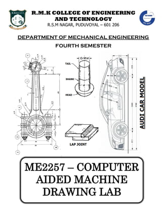
  • 1. R.M.K COLLEGE OF ENGINEERING AND TECHNOLOGY R.S.M NAGAR, PUDUVOYAL – 601 206 DEPARTMENT OF MECHANICAL ENGINEERING FOURTH SEMESTER ME2257 – COMPUTER AIDED MACHINE DRAWING LAB
  • 2. DEPARTMENT OF MECHANICAL ENGINEERING Computer Aided Machine Drawing Lab Manual By Ashok Kumar. R (AP / MECH) 2 ME2257 – COMPUTER AIDED MACHINE DRAWING OBSERVATION NOTE BOOK
  • 3. DEPARTMENT OF MECHANICAL ENGINEERING Computer Aided Machine Drawing Lab Manual By Ashok Kumar. R (AP / MECH) 3 IV SEM MECHANICAL ENGINEERING ME2257 – COMPUTER AIDED MACHINE DRAWING LAB LIST OF EXERCISES I) STUDY OF DRAWING STANDARDS & ASSEMBLY DRAWING 1) Study of Drawing Standards 2) Study of Welding Symbols 3) Study of Riveted Joints 4) Study of Keys 5) Study of Screw Threads and Threaded Fasteners 6) Study of Limits, Tolerance and Fits 7) Study of Assembly Drawings II) ASSEMBLY DRAWING 8) Assembly Drawing of Muff Coupling in 2D 9) Assembly Drawing of Half Lap Muff Coupling in 2D 10) Assembly Drawing of Split Muff Coupling in 2D 11) Assembly Drawing of Unprotected Flange Coupling in 2D 12) Assembly Drawing of Protected Flange Coupling in 2D 13) Assembly Drawing of Universal Coupling in 2D 14) Assembly Drawing of Knuckle Joint in 2D
  • 4. DEPARTMENT OF MECHANICAL ENGINEERING Computer Aided Machine Drawing Lab Manual By Ashok Kumar. R (AP / MECH) 4 15) Assembly Drawing of Screw Jack in 2D 16) Assembly Drawing of Stuffing Box in 2D 17) Assembly Drawing of Plummer Block in 2D 18) Assembly Drawing of Connecting Rod in 2D 19) Assembly Drawing of Non Return Valve in 2D 20) Assembly Drawing of Safety Valve in 2D 21) Assembly Drawing Of Machine Vice in 2D 22) Assembly Drawing Of Tail Stock in 2D III) ADDITIONAL CONTENT BEYOND THE SYLLABUS 23) AUDI car model in 2D 24) BMW car model in 2D
  • 5. DEPARTMENT OF MECHANICAL ENGINEERING Computer Aided Machine Drawing Lab Manual By Ashok Kumar. R (AP / MECH) 5 IV SEM MECHANICAL ENGINEERING ME2257 – COMPUTER AIDED MACHINE DRAWING LAB SYLLABUS DRAWING STANDARDS Code of practice for Engineering Drawing, BIS specifications – Welding symbols, rivetedjoints, keys, fasteners – Reference to hand book for the selection of standard components like bolts, nuts, screws, keys etc. 2-D DRAWINGS Limits, Fits – Tolerancing of individual dimensions- Specification of Fits- Manual Preparation of production drawings and reading of part and assembly drawings. CAD PRACTICE (USING APPLICATION PACKAGES) Drawing, Editing, Dimensioning, Plotting Commands, Layering Concepts, Hatching, Detailing, Assembly, basic principles of GD&T (geometric dimensioning &tolerancing) ASSEMBLY DRAWING (MANUAL & USING APPLICATION PACKAGES) Manual parts drawing and preparation of assembled views given part details for components followed by practicing the same using CAD packages. SUGGESTED ASSEMBLIES: Shaft couplings – Plummer block – Screw jack- Lathe Tailstock – Universal Joint – Machine Vice – Stuffing box – safetyValves – Non-return valves– Connecting rod –Piston and crank shaft– Multi plate clutch – Preparationof Bill of materials and tolerance data sheet
  • 6. DEPARTMENT OF MECHANICAL ENGINEERING Computer Aided Machine Drawing Lab Manual By Ashok Kumar. R (AP / MECH) 6 INDEX EXPT NO DATE NAME OF THE EXPERIMENT PAGE NO SIGN 1) 2) 3) 4) 5) 6) 7) 8) 9) 10) 11) 12) 13) 14)
  • 7. DEPARTMENT OF MECHANICAL ENGINEERING Computer Aided Machine Drawing Lab Manual By Ashok Kumar. R (AP / MECH) 7 EXPT NO DATE NAME OF THE EXPERIMENT PAGE NO SIGN 15) 16) 17) 18) 19) 20) 21) 22) 23) 24) 25) Signature of Lab in Charge Signature of HOD
  • 8. DEPARTMENT OF MECHANICAL ENGINEERING Computer Aided Machine Drawing Lab Manual By Ashok Kumar. R (AP / MECH) 8 STUDY OF DRAWING STANDARDS EXPT NO: 1 DATE: AIM: To study about the basic fundamentals of the drawing standards used in machine drawing. CODE OF PRACTICE FOR ENGINEERING DRAWING: The representation of any matter by some sign or mark on the drawing is known as convention or Code. These conventions are specified by Bureau of Indian Standards (BIS) and are called BIS specifications. ISO STANDARDS: In the 21st century, growing international engineering and technological developments, technical collaboration between mutual countries, exchange and export of technologies and globalization leading to the establishment of various Multi-National Companies (MNCs) have necessitated the inter-nationalization of engineering drawing standards. INTERNATIONAL STANDARDS ORGANIZATION (I.S.O), Geneva, Switzerland, have formulated (1970) international standards for engineering drawing, for which our country has also given the approval and accordingly modified the Indian Standards IS 696:1972. B.I.S: Indian Standards Institution (I.S.I) is renamed as Bureau of Indian Standards (B.I.S) in 1983.Engineering Drawing Committee (E.D.C) of B.I.S has adopted the I.S.O standards in Toto for the various topics given in the following Table.
  • 9. DEPARTMENT OF MECHANICAL ENGINEERING Computer Aided Machine Drawing Lab Manual By Ashok Kumar. R (AP / MECH) 9 Sl.No BIS Codes Topics 1) IS: 9609 (Parts 0 & 1) – 2001 Technical product documentation – Lettering 2) IS: 10711 – 2001 Technical products documentation – size and layout of drawing sheets 3) IS : 10713 – 1983 Scales for use on Technical Drawing 4) IS : 10714 – 1983 General Principles of Presentation 5) IS: 10714 (Part 20) – 2001 Lines 6) IS : 10715 – 1983 Presentation of threaded parts on technical drawing 7) IS : 10716 – 1983 Rules for presentation of springs 8) IS : 10717 – 1983 conventional representation of gears on technical drawing 9) IS : 11663 – 1986 Conventional representation of common features 10) IS : 11664 – 1986 Folding of drawing prints 11) IS : 11665 – 1986 Technical drawing – Title blocks 12) IS : 11669 – 1986 Dimensioning on Technical Drawings 13) IS : 11670 – 1986 Abbreviation’s for use in Technical Drawing 14) IS: 15021 (Parts 1-4) – 2001 Technical Drawings – Projection Methods 15) IS: 7008 – 1988 Acme or Trapezoidal thread 16) IS 4218 – 1976 IS 11698 – 1986 Metric screw threads 17) IS: 2292 – 1974 Taper keys 18) IS: 2293 – 1974 Gib – head keys 19) IS: 2048 – 1983 Feather keys 20) IS: 2294 – 1986 Woodruff keys 21) IS: 2327 – 1991 Spline shafts 22) IS 919 – 1963 Limits & Fits for engineering
  • 10. DEPARTMENT OF MECHANICAL ENGINEERING Computer Aided Machine Drawing Lab Manual By Ashok Kumar. R (AP / MECH) 10 RESULT: Thus the basic fundamentals of the drawing standards used in machine drawing was studied.
  • 11. DEPARTMENT OF MECHANICAL ENGINEERING Computer Aided Machine Drawing Lab Manual By Ashok Kumar. R (AP / MECH) 11 BASIC WELD SYMBOLS S.NO FORM OF WELD DIAGRAM SYMBOL 1) FILLET 2) SQUARE BUTT 3) SINGLE – V BUTT 4) DOUBLE – V BUTT 5) SINGLE – U BUTT 6) DOUBLE – U BUTT 7) SINGLE – BEVEL BUTT 8) DOUBLE – BEVEL BUTT 9) SINGLE – J BUTT 10) DOUBEL – J BUTT 11) EDGE 12) SPOT
  • 12. DEPARTMENT OF MECHANICAL ENGINEERING Computer Aided Machine Drawing Lab Manual By Ashok Kumar. R (AP / MECH) 12 STUDY OF WELDING SYMBOLS EXPT NO: 2 DATE: AIM: To study about the welding symbols. WELDING: It is a technique of making permanent joint. It is the process of joining two parts of metal by fusing them together. TYPES OF WELDING:  Pressure welding or Forge welding  Forge welding  Thermit pressure welding  Pressure gas welding  Electric resistance welding  Fusion welding  Gas welding  Electric arc welding  Thermit fusion welding  Fusion pressure welding  Spot welding  Seam welding  Flash butt welding
  • 13. DEPARTMENT OF MECHANICAL ENGINEERING Computer Aided Machine Drawing Lab Manual By Ashok Kumar. R (AP / MECH) 13
  • 14. DEPARTMENT OF MECHANICAL ENGINEERING Computer Aided Machine Drawing Lab Manual By Ashok Kumar. R (AP / MECH) 14 TYPES OF WELD JOINTS:  Butt joint  Corner joint  Tee joint  Lap joint  Edge joint SYMBOLIC REPRESENTATION OF WELD: Welded joints are symbolically represented as shown in figure.  An arrow line pointing to the joint where the weld to be made.  A dual reference line consisting of two parallel lines, one continuous and one dashed.  A basic symbol to specify the type of weld.  A supplementary symbol to characterize the shape of the external surface on the weld.  Dimension of the weld. ARROW LINE AND REFERENCE LINE: The position of the arrow line with respect to the weld is of no special significance. The side of the joint on which the arrow line is drawn is called “arrow side”. The side of the joint remote to the arrow line is called “other side”. The reference line has significance on the weld side. If the weld symbol is placed BELOW the reference line, the welding should be done in the “ARROW SIDE”. If the weld symbol is placed ABOVE the reference line, the welding should be done in the “OTHER SIDE”. If the weld symbol is placed both
  • 15. DEPARTMENT OF MECHANICAL ENGINEERING Computer Aided Machine Drawing Lab Manual By Ashok Kumar. R (AP / MECH) 15 EDGE PREPARATION FORM OF WELD DIAGRAM FORM OF WELD DIAGRAM SQUARE BUTT SINGLE FILLET SINGLE – V BUTT DOUBLE FILLET DOUBLE – V BUTT STRAIGHT BEVEL SINGLE – U BUTT SINGLE BEVEL DOUBLE – U BUTT DOUBLE BEVEL SINGLE – BEVEL BUTT SINGLE J BEVEL DOUBLE – BEVEL BUTT DOUBLE J BEVEL SINGLE – J BUTT EDGE JOINT DOUBEL – J BUTT CORNER JOINT
  • 16. DEPARTMENT OF MECHANICAL ENGINEERING Computer Aided Machine Drawing Lab Manual By Ashok Kumar. R (AP / MECH) 16 ABOVE and BELOW the reference line, the welding should be done in both the “ARROW AND OTHER SIDES”. EDGE PREPARATION: The preparation of the edges of the pieces to be welded depends upon the thickness of metal being welded Edge preparation is necessary when thickness increases so that heat would be able to penetrate the entire depth. This ensures formation of sound welds. The edge preparation is done by beveling the edges of the pieces after the rust, grease, oil or paint are completely removed from their surfaces. RESULT: Thus the welding symbols were studied.
  • 17. DEPARTMENT OF MECHANICAL ENGINEERING Computer Aided Machine Drawing Lab Manual By Ashok Kumar. R (AP / MECH) 17
  • 18. DEPARTMENT OF MECHANICAL ENGINEERING Computer Aided Machine Drawing Lab Manual By Ashok Kumar. R (AP / MECH) 18 STUDY OF RIVETED JOINTS EXPT NO: 3 DATE: AIM: To study about the riveted joints. RIVET: Rivets are short cylindrical pieces, made of mild steel or non – ferrous materials such as copper, aluminum. A rivet consists of a head, cylindrical body or shank and a slightly tapered tail. If l = Length of the shank of the rivet d = Diameter of rivet t = Thickness of each of the connecting plates RIVETING: It is the process of forming a well – shaped concentric head from the projection portion of the shank end of the rivet inserted in the holes previously drilled in the plates to be fastened. The riveting process involves making of the holes in the plates and the formation of the rivet head CAULKING & FULLERING: In boilers and hydraulic tanks containing pressurized fluids, there are possibilities of leak at the joints between the two overlapping plates, or between the bearing plate and underneath of the rivet head. Therefore the riveted joints of the boilers and tile hydraulic tanks have to be made leak – proof. This is accomplished by burring down or forcing down the edges of the rivet heads and the plates. This will force the edge of the plate or the rivet head to bite into the bearing plate which makes the joint leak – proof.
  • 19. DEPARTMENT OF MECHANICAL ENGINEERING Computer Aided Machine Drawing Lab Manual By Ashok Kumar. R (AP / MECH) 19
  • 20. DEPARTMENT OF MECHANICAL ENGINEERING Computer Aided Machine Drawing Lab Manual By Ashok Kumar. R (AP / MECH) 20 The burring down of the edges of the rivet head or the plates is accomplished by hammering down by a blunt chisel like tool of about 5mm thick and 50 mm in breadth with the edge ground at an angle of 80°, known as caulking tool as shown in Figure, along the edges of the plates and all-round the rivet head. This operation is called caulking. Another, more satisfactory method of burring down the edges of the plates is by the use of fullering tool, similar to the caulking tool but the thickness of the tool is equal to that of the plates as shown in the Figure. To facilitate the fullering operation the edges of the plates will be previously chamfered or bevelled to an angle of 80° before the joint is made. The fullering operation increases this angle to 80°. The Figure shows the use of a tool which combines both the caulking and fullering operations. APPLICATIONS OF RIVETED JOINTS: A riveted joint is a permanent type of fastener used to join the metal plates or rolled steel sections together. Riveted joints are extensively used in structural works such as bridges and roof trusses and in the construction of pressure vessels such as storage tanks, boilers, etc. Although welded joints are best suited to several of these applications than the riveted joints, however, riveted joints are ideal in cases where the joints will be subjected to pronounced vibrating loads. Riveted joints are also used when a non-metallic plate and a metallic plate are to be connected together. They are also used when the joints are not expected to be heated while joining as in welding, which may cause warping and tempering of the finished surfaces of the joints. The disadvantage of riveted joints are: (i) more metal is removed while making of the holes, which weakens the working cross sections along the line of the rivet holes, and (ii) weight of the rivets increases the weight of the riveted members. TYPES OF RIVETS:  Snap Head  Pan Head
  • 21. DEPARTMENT OF MECHANICAL ENGINEERING Computer Aided Machine Drawing Lab Manual By Ashok Kumar. R (AP / MECH) 21
  • 22. DEPARTMENT OF MECHANICAL ENGINEERING Computer Aided Machine Drawing Lab Manual By Ashok Kumar. R (AP / MECH) 22  Pan Head with Tapper Neck  Counter Sunk Head  Flat Counter Sunk Head  Rounded Counter Sunk Head  Mushroom Head  Ellipsoidal head  Conical head  Steeple Head  Flat Head TYPES OF RIVETED JOINTS:  Lap joint  Butt joint
  • 23. DEPARTMENT OF MECHANICAL ENGINEERING Computer Aided Machine Drawing Lab Manual By Ashok Kumar. R (AP / MECH) 23
  • 24. DEPARTMENT OF MECHANICAL ENGINEERING Computer Aided Machine Drawing Lab Manual By Ashok Kumar. R (AP / MECH) 24 LAP JOINT: The simplest way to connect two plates by riveting is to overlap them over a short distance along their edges and drill a row of holes though both of them in the overlapped portion and a joint are made by riveting as shown in figure. This type of joint is called a lap joint. When a lap joint is subjected to a pull as shown in Figure. Since the plates are not in the same plane, they develop a tendency to pull themselves along a plane resulting in their buckling as shown Figure which develops an axial pull in the rivets. Since the rivets are not designed to take up axial tensile forces, their heads may 'fly off". BUTT JOINT: When the plates are intended to take heavy loads, the buckling action of the plates may be avoided by placing the connecting plates in alignment so as to butt each other and a cover plate called strap is placed over the joint between them and riveted to hold both the plates together as shown in Figure. This type of joint is called butt joint. In a butt joint, the load is transferred from one of the butt plates to the cover plate and then from the cover plate to the other butt plate. With this kind of arrangement, the rivets will be subjected to shear forces for which they are designed. Even the butt joint with a cover plate on only one side, called butt joint with single cover plate, may also be subjected to buckling as shown in Figure. Since this arrangement has cover plates on both the sides of the joint, it is called butt joint with double cover plates. Generally the butt joints are provided with double cover plates. TERMINOLOGY: The definitions of the different terms used in the riveted joints are given below. Longitudinal Pitch – P: It is the distance from the centre of one rivet to the centre of the next rivet in the same row measured parallel to the caulking edge of the plate.
  • 25. DEPARTMENT OF MECHANICAL ENGINEERING Computer Aided Machine Drawing Lab Manual By Ashok Kumar. R (AP / MECH) 25
  • 26. DEPARTMENT OF MECHANICAL ENGINEERING Computer Aided Machine Drawing Lab Manual By Ashok Kumar. R (AP / MECH) 26 Margin – m: It is the distance between the edge of the plate and the nearest rivet hole. The margin is always taken equal to the rivet diameter. Since m=d, the distance between the centre of the rivet and the caulked or fullered edge of the plate will always be equal to 1.5d. Transverse Pitch – Pt: It is the perpendicular distance between the rows of rivets. It is called as row pitch. Diagonal Pitch – Pd: It is the distance from the centre of a rivet in a row to the centre of the next rivet in the adjoining row. Back Pitch– Pb: It is the perpendicular distance between consecutives rows of rivets. Nominal Diameter: It is the diameter of the shank of the rivet before riveting.
  • 27. DEPARTMENT OF MECHANICAL ENGINEERING Computer Aided Machine Drawing Lab Manual By Ashok Kumar. R (AP / MECH) 27
  • 28. DEPARTMENT OF MECHANICAL ENGINEERING Computer Aided Machine Drawing Lab Manual By Ashok Kumar. R (AP / MECH) 28 RESULT: Thus the riveted joints were studied.
  • 29. DEPARTMENT OF MECHANICAL ENGINEERING Computer Aided Machine Drawing Lab Manual By Ashok Kumar. R (AP / MECH) 29
  • 30. DEPARTMENT OF MECHANICAL ENGINEERING Computer Aided Machine Drawing Lab Manual By Ashok Kumar. R (AP / MECH) 30 STUDY OF KEYS EXPT NO: 4 DATE: AIM: To study about different types of keys. KEYS: A key is a metal piece inserted in an axial direction between a shaft and a hub to prevent relative rotation keys mainly used to hold pulley gears wheels etc. The keywill be driven such that it sits partly into the shaft and partly into hub. SUNK TAPER KEY: A Sunk taper key shown in Figure is of rectangular or square cross section of uniform width having its bottom surface straight and top surface tapered. The key is driven between the shaft and hub with half of its thickness to fit in the flat key way made in the shaft and the other half having the tapered surface to fit in the tapered key way made in the hub. This type of key is generally used transmit heavy loads. If D – Diameter of the shaft in mm W – Width of the key = 0.25D + 2 mm T – Nominal thickness = 0.66W Standard taper = 1 : 100 HOLLOW SADDLE KEY: A hollow saddle key is of uniform width but in thickness its upper side is flat and the underside is hollow. Since the saddle key holds the shaft and the part mounted on it only by friction, it is not suitable for heavy loads. This key is used when there is frequent alternations in the position of the key on the shaft is expected. If D – Diameter of the shaft in mm
  • 31. DEPARTMENT OF MECHANICAL ENGINEERING Computer Aided Machine Drawing Lab Manual By Ashok Kumar. R (AP / MECH) 31
  • 32. DEPARTMENT OF MECHANICAL ENGINEERING Computer Aided Machine Drawing Lab Manual By Ashok Kumar. R (AP / MECH) 32 W – Width of the key = 0.25D + 2 mm T – Nominal thickness = 0.33W Standard taper = 1 : 100 FLAT SADDLE KEY: A flat saddle key is similar to a hollow saddle key, except that it’s underneath surface is flat. The key sits over the flat surface formed on the shaft and fits into the key way in the hub. When the shaft rotates, the key will be wedged between the flat surface on the shaft and the keyway in the hub, and thus holds them to rotate together. It is not used for heavy loads and not suitable for shafts which frequently changed their direction of rotation. If D – Diameter of the shaft in mm W – Width of the key = 0.25D + 2 mm T – Nominal thickness = 0.33W Standard taper = 1 : 100 GIB – HEAD KEY: When a tapered sunk key is used, it can be removed by striking exposed thin end. If this end is not accessible, a head called gib is provided integral with the sunk taper key at its thicker end as shown figure. When a gib – head key is to be removed, a wedge is forced vertically in the gap between the head of the key and the vertical face of the hub. If D – Diameter of the shaft in mm W – Width of the key = 0.25D + 2 mm T – Nominal thickness = 0.66W Height of Gib – head = 1.75T Width of Gib – head = 1.5T FEATHER KEY OR PARALLEL KEY: A feather key or a parallel key permits an axial sliding movement for the wheel over a shaft when both of them are rotating together. A feather key is of rectangular or square cross section with uniform width and thickness as shown in figure. The ends of the feather key are
  • 33. DEPARTMENT OF MECHANICAL ENGINEERING Computer Aided Machine Drawing Lab Manual By Ashok Kumar. R (AP / MECH) 33
  • 34. DEPARTMENT OF MECHANICAL ENGINEERING Computer Aided Machine Drawing Lab Manual By Ashok Kumar. R (AP / MECH) 34 usually rounded and the key will be sunk into the shaft for half of its thickness so that it fits snugly into the key way recess it with press fit. If D – Diameter of the shaft in mm W – Width of the key = 0.25D + 2 mm T – Nominal thickness = 0.66W SINGLE HEAD KEY: A single head key is also a feather type key provided with a gib head at one of its ends as shown in figure. The key is connected to the hub by a screw. The key is sliding fot in the shaft. The proportions of the key are as follows If D – Diameter of the shaft in mm W – Width of the key = 0.25D + 2 mm T – Nominal thickness = 0.66W Height of head = 1.75T Width of head = 1.5T DOUBLE HEAD KEY: A double head key is also a feather type of key having integral gib head as shown in figure. It fits tight in the hub and slides along with it in the key way in the shaft. The proportions of the key are as follows If D – Diameter of the shaft in mm W – Width of the key = 0.25D + 2 mm T – Nominal thickness = 0.66W Height of head = 1.75T Width of Gib = 1.5T RESULT: Thus the different types of keys were studied.
  • 35. DEPARTMENT OF MECHANICAL ENGINEERING Computer Aided Machine Drawing Lab Manual By Ashok Kumar. R (AP / MECH) 35
  • 36. DEPARTMENT OF MECHANICAL ENGINEERING Computer Aided Machine Drawing Lab Manual By Ashok Kumar. R (AP / MECH) 36 STUDY OF SCREW THREADS AND THREADED FASTENERS EXPT NO: 5 DATE: AIM: To study about screw threads and fasteners. SCREW AND SCREW THREAD: A screw is a cylindrical or a conical rod with a helical groove cut on it. Its function is to transform the input motion of rotation into output motion of translation. A screw thread is a continuous helical ridge formed by cutting a helical groove on a cylindrical or conical shank. SCREW THREAD TERMINOLOGY External thread – It is a continuous helical ridge on the external surface of the cylinder. Internal thread – It is a thread on the internal surface of a cylinder. The thread on the surface of a hole of a nut is an internal thread. Right hand thread – If a threaded element viewed axially, a point moving clockwise along the thread moves away from the observer the thread is a right hand thread. Left hand thread – If a threaded element viewed axially, a point moving anticlockwise along the thread moves away from the observer the thread is a left hand thread. Depth of the thread – It is the distance between the crest and the root of the thread which is measured normal to the axis on an axial plane. Angle of the thread – It is the angle includes between the sides of the two adjacent threads and is measured on an axial plane.
  • 37. DEPARTMENT OF MECHANICAL ENGINEERING Computer Aided Machine Drawing Lab Manual By Ashok Kumar. R (AP / MECH) 37
  • 38. DEPARTMENT OF MECHANICAL ENGINEERING Computer Aided Machine Drawing Lab Manual By Ashok Kumar. R (AP / MECH) 38 Thread angle – The distance between the flanks, measured in an axial plane, is known as thread angle. Nominal Diameter – It is the diameter of the cylindrical rod on which the threads are cut. This diameter specifies the size of the screw. Major Diameter – It is the diameter of an imaginary coaxial cylinder which bounds the crests of an external thread or the roots of an internal thread. D and d denote the major diameters of the internal and external threads respectively. Minor, or Core, or Root Diameter – It is the diameter of an imaginary coaxial cylinder which bounds the root so fan external thread, or the crests of an internal thread. DI and d3, denote the minor diameters of the internal and external thread respectively. Pitch Diameter – It is the diameter of the thread at which an imaginary coaxial cylinder that can be passed so as to cut the thread so that the width of the cut thread will be equal to the width of the groove. D2and d2, denote the pitch diameters of internal and external threads respectively. Root – It is the bottom portion of the surface of a thread, either flat or rounded which joins the sides of the adjacent threads. Crest – It is the top portion of the surface of a thread, either flat or rounded which joins the sides of the same thread. Flank or Side – It is the surface of a thread that connects the crest with the root and also it offers the surface contact with its counterpart. Height of the Fundamental Triangle –The imaginary equilateral triangle which bounds a V – thread is called a fundamental triangle. In Figure, the triangle ABC is called the fundamental triangle. Its height, His measured normal to the axis on an axial plane.
  • 39. DEPARTMENT OF MECHANICAL ENGINEERING Computer Aided Machine Drawing Lab Manual By Ashok Kumar. R (AP / MECH) 39
  • 40. DEPARTMENT OF MECHANICAL ENGINEERING Computer Aided Machine Drawing Lab Manual By Ashok Kumar. R (AP / MECH) 40 Pitch – It is the distance from a point on a screw thread to a corresponding point on the next thread, measured parallel to the axis. It may be indicated as the distance from crest to crest; or from root to root, but the former is the convention. Lead – It is the axial distance advanced by a nut for its one full turn over a threaded rod. On a single start thread, the lead and the pitch are identical. On a double start thread, the lead is twice the pitch, and on a triple start thread, the lead is three times the pitch. Thus, the lead may also be defined as the product of the pitch and number of starts. DIFFERENCE BETWEEN ‘V’ AND SQUARE THREADS: V THREAD SQUARE THREAD  V - Threads have inclined flanks making an angle between them.  V – Threads have a larger contact area providing more frictional resistance to motion. So they are more suitable for fastening.  V – Threads are stronger than the square threads.  V – Threads are cheap because they can be cut easily by a die or on machines.  Examples for V – threads are the thread used in bolts, nuts and studs.  The flanks of square threads are perpendicular to thread axis and parallel to each other.  Square threads offer less friction to relative motion. The normal force between the threads acts parallel to the axis with zero radial components. So they are suitable for power transmission.  Square threads have only half the resisting the power, resting the shearing action.  Square threads are costly.  Examples for square threads are lead screw of a lathe, screw jack etc.,
  • 41. DEPARTMENT OF MECHANICAL ENGINEERING Computer Aided Machine Drawing Lab Manual By Ashok Kumar. R (AP / MECH) 41
  • 42. DEPARTMENT OF MECHANICAL ENGINEERING Computer Aided Machine Drawing Lab Manual By Ashok Kumar. R (AP / MECH) 42 STANDARD FORMS OF V – THREADS: Whitworth Thread – British Standard This thread was introduced by Sir Joseph Whitworth and was standardized as British Standard thread, abbreviated as BSW. The profile of the thread is shown in figure. It has a thread angle of 55˚ and is rounded off at the crest and roots. Sellers Thread – Earlier American Standard This thread was adopted earlier as the American standard thread by the American Standards Institution. The profile of the thread is shown in figure. It has a thread angle of 60˚ between the crest and roots are kept flat. Unified Thread – ISO Thread – Indian Standard The Bureau of Indian Standard has adopted V – thread profile recommended by the International Organizations for Standards, ISO, metric screw thread for use in this country. This thread is also known as Unified Thread. The profile of the thread is shown in figure. It has a thread angle of 60˚
  • 43. DEPARTMENT OF MECHANICAL ENGINEERING Computer Aided Machine Drawing Lab Manual By Ashok Kumar. R (AP / MECH) 43
  • 44. DEPARTMENT OF MECHANICAL ENGINEERING Computer Aided Machine Drawing Lab Manual By Ashok Kumar. R (AP / MECH) 44 STANDARD FORMS OF SQUARE THREAD: Basic Form of Square Thread The basic form square thread is shown in figure. The flanks or the sides of this thread are perpendicular to axis of the thread. The depth and the thickness of the thread equal to half the pitch. Square Threads – Indian Standard The profile of the square thread adopted by the Bureau of Indian Standards is shown in figure. The depth of the external thread is equal to half of the pitch. The sharp corners at the root of the external threads are rounded off to the radius R = 0.25mm. The depth of the internal threads is equal to 0.5P + 0.25mm. The sharp corners at the crest of the internal threads are chamfered to 0.25mm * 45˚. MODIFIED FORMS OF SQUARE THREADS: Acme Thread This thread is modified from square thread. It is easier to cut and is stronger at the root. The angle of the thread is 29˚. The inclined sides of the thread facilitate quick and early engagement and disengagement. It is used for power screws like lead screw of lathe, jackscrews, bench vices and valve operating screws. Buttress Thread The profile of this thread is a combination of square and V – threads. It combines the low frictional of square and ability to transmit power of square thread and the strength of V – thread. It is used to transmit load in uni – direction. These threads are used in screw press, vices. Knuckle Thread It is also a modification of square thread. The sharp corners of square thread are rounded off. This thread is used where heavy wear rough use is expected. The thread can be rolled or cast
  • 45. DEPARTMENT OF MECHANICAL ENGINEERING Computer Aided Machine Drawing Lab Manual By Ashok Kumar. R (AP / MECH) 45
  • 46. DEPARTMENT OF MECHANICAL ENGINEERING Computer Aided Machine Drawing Lab Manual By Ashok Kumar. R (AP / MECH) 46 easily. It is used in railway carriage coupling screws, light bulbs and sockets, bottle caps and also objects made of brittle materials as glass, plastic, porcelains etc. THREADED FASTENERS: Threaded fasteners are temporary fasteners, which hold the parts together throughthe medium of a screw thread. These are used in pairs for their action (for example, a nut and a bolt). They have the advantage over permanent fasteners of allowing assembly of parts when required. A wide variety of threaded fasteners are in use. Some of them are standardized and others are made for special use. COMMON TYPE OF THREADED FASTENERS: The five types of threaded fasteners in common use are  Bolt  Stud  Cap screw  Machine screw  Setscrew All these with external threaded and used in combination with another having corresponding internal threads (eg) a nut or a tapped hole. BOLTS: A bolt is a metal having a head at one end and a threaded portion to a definite length on other end. The head is formed by forging or machining. The bolt is admitted through holes in the parts, which are to be fastened. The projected thread end of the bolt admits a corresponding nut from the other side. Tightening the bolt by turning gives necessary clamping grip to hold the parts together. Bolts and nuts of various shapes are used for different purpose but the hexagonal head and square head are very common. Although, the square shape provides better spanner grip than the hexagon, but needs one fourth of a turn to bring it into the same position for inserting spanner again, whereas a hexagon need only one sixth of a turn and hence provided.
  • 47. DEPARTMENT OF MECHANICAL ENGINEERING Computer Aided Machine Drawing Lab Manual By Ashok Kumar. R (AP / MECH) 47
  • 48. DEPARTMENT OF MECHANICAL ENGINEERING Computer Aided Machine Drawing Lab Manual By Ashok Kumar. R (AP / MECH) 48 The sharp corners on the external flat end faces of bolt heads and nuts are chamfered conically at 30˚ to ensure safety of the user. To facilitate early insertion of the nut over the bolt, the threaded holes in the nut are countersunk. Three dimensions are usually sufficient for simplified representation of a bolt The bolt shank diameter (d) The bolt length (l) The length of a threaded portion of the shank (b) EMPIRICAL PORTIONS OF HEXAGON AND SQUARE HEAD BOLT & NUT DETAIL PROPORTION: Nominal diameter d = size of bolt or nut mm Width across flats s =1.5d+3mm Width across corners e =2d Thickness of bolt head k =0.8d Thickness of nut n =0.9d Root diameter d1 =d–(2*depth of thread) Length of the bolt l =as specified Thread length b =2d+6mm (for l<150mm) =2d+12mm (for l>150mm) Chamfer of bolt end Z =depth of thread*45(degree) (or) =0.1d Chamfer angle of bolt head & nut = 30˚ DRAWING OF HEXAGONAL NUT AND BOLT STEP: 1 Draw the shank of the bolt equal to the given diameter (d) and length (l).The thickness of the bolt head equals to 0.8d and the thickness of nut equal to 0.9d are marked. Measure the width across corners equal to 2d and complete the three faces of the bolt head and nut in these lines.
  • 49. DEPARTMENT OF MECHANICAL ENGINEERING Computer Aided Machine Drawing Lab Manual By Ashok Kumar. R (AP / MECH) 49
  • 50. DEPARTMENT OF MECHANICAL ENGINEERING Computer Aided Machine Drawing Lab Manual By Ashok Kumar. R (AP / MECH) 50 The right hand view of the bolt and nut assembly is drawn as follows with any point on the axis as centre and radius equal to draw a thin circle. A hexagon is inscribed inside this circle. The chamfer circle is drawn as a thick circle with the centre C1 and radius C1E. STEP: 2 The chamfer arcs in three face view of bolt head and nut are drawn as follows. Through the corner B, draw a line 30˚ to the axis of the bolt or nut to cut it at O1. With O1 as centre O1A draw the chamfer arc in the centre face.The chamfer arcs on the two side faces are drawn as follows. Draw the perpendicular bisector of BC to cut BO1 at O2 as centre and radius O2D draw the chamfer arc. Repeat the construction on the other side face. STEP: 3 The chamfer lines on the side faces of the three face views of the bolt head and nut are drawn through the points P and Q inclined at 30˚ to the flat faces of the bolt. The end of the bolt is chamfered 0.1d*45˚. The threaded portion of the shank is indicated, by drawing two thin lines at a distance equal to d1=0.9d.the root circle in the right view is represented by a thin three-fourth of a circle of diameter 0.9d. STEP: 4 The two face view of the bolt head and nut is projected from the side view. If the side view is not drawn, then the distance across the flats is measured equal 1.5d + 3mm. The chamfer arcs in the two face view are drawn as follows. Project P to get X. Mark Y the midpoint of FG. Draw the perpendicular bisector of XY and FG to intersect each other at O3. With centre O3 and radius O3Y draw the chamfer arc. Repeat the construction on the other face DRAWING OF SQUARE HEAD BOLT AND NUT: STEP: 1 Draw the shank of the bolt equal to the given diameter d and the length of the bolt. The thickness of the bolt head is equal to 0.8d and the thickness of the nut is equal to 0.9d are marked. The right hand view of the bolt and nut assembly is drawn as follows. With any
  • 51. DEPARTMENT OF MECHANICAL ENGINEERING Computer Aided Machine Drawing Lab Manual By Ashok Kumar. R (AP / MECH) 51
  • 52. DEPARTMENT OF MECHANICAL ENGINEERING Computer Aided Machine Drawing Lab Manual By Ashok Kumar. R (AP / MECH) 52 pointC1 on the axis as centre and diameter equal to 1.5d+3mm draw a chamfer circle with its sides inclined at 45˚ to the axis. Project the corners 1 and 2 to get to get point P.Drawa thick circle with diameter d to indicate the nominal diameter. STEP: 2 The chamfer arcs in the view across the corners of the bolt and nut are drawn as follows. Through the corner P, draw a line inclined at 30˚ to the axis. Draw the perpendicular bisector of PQ to intersect the 30˚ line at O. With O as centre and radius OR draw the chamfer arc. Repeat the construction on the other face. STEP: 3 The chamfer line is drawn at 30˚ to the flat face of the bolt head and nut. The threaded portion on the shank of the bolt is indicated by drawing two thin line spaced at a distance equal to the root diameter d1=0.9d. The root circle in the right view is represented by a thin three-fourth of a circle with centre C1 and diameter 0.9. The end of the bolt is chamfered to 0.1d*45˚. SPECIAL TYPES OF BOLTS: In practice various types of bolts than the hexagon and square head bolts are used in where the bolt head cannot be held by the spanner when the nut is turned on or off the bolt. The rotation of the bolt prevented by a stop pin or a snug or a square neck provided below the head. CYLINDRICAL OR CHEESE HEADED BOLT: The head of this type of bolt is of cup shape and the rotation of the bolt head is prevented by a stop pin. The stop pin may be driven into the shank with its axis perpendicular to the axis of the bolt. The stop pin may also be driven into the head adjacent to the shank with its axis parallel to the axis of the bolt. These types of bolt heads are used in the big ends of the connecting rods, eccentrics, cross heads etc...
  • 53. DEPARTMENT OF MECHANICAL ENGINEERING Computer Aided Machine Drawing Lab Manual By Ashok Kumar. R (AP / MECH) 53
  • 54. DEPARTMENT OF MECHANICAL ENGINEERING Computer Aided Machine Drawing Lab Manual By Ashok Kumar. R (AP / MECH) 54 COUNTER SUNK HEAD BOLT: CUP OR ROUND HEADED BOLT: Two types of cup head bolts are available. In one type, a snug is provided which prevents the rotation of bolt head. The other type, a square neck is provided which will fit into the square hole provided in the bearing surface and thus prevents the rotation of the bolt head. The counter sunk head bolts are used when the bolt head must not project and foul with surfaces. The counter sunk bolt is provided with a stop pin of square cross section integral with the head. The other type of counter sunk bolt is provided with the square neck below the head. This type of bolt is also called as “coach bolt”. T – HEAD BOLT: Two types of T bolts are shown in figure. The T head bolt is provided with a square neck underneath the head to prevent the rotation of the bolt. This type of the bolt is used to connect the covers or the flanges where there is sufficient space to accommodate the hexagon head blot. The other T – head bolt is used for securing vices, jigs, work pieces to the tables of the machine tools like shaping, planning, drilling machine, where frequent tightening and loosening are carried. EYE BOLT: The head of the bolt is in the form of circular form of rectangular cross section. It is generally used in the inspection covers, lids etc..., which have to be opened and closed frequently. LIFTING EYE BOLT: The lifting eye bolt, having a circular ring of circular cross section as head. A flat circular portion, integral with a head is also provided. This type of bolt is used for lifting a heavy machine such as motors, pumps, turbine, electrical generators etc., This bolt is screwed in a threaded hole provided for this purpose , on the top of the machine directly
  • 55. DEPARTMENT OF MECHANICAL ENGINEERING Computer Aided Machine Drawing Lab Manual By Ashok Kumar. R (AP / MECH) 55
  • 56. DEPARTMENT OF MECHANICAL ENGINEERING Computer Aided Machine Drawing Lab Manual By Ashok Kumar. R (AP / MECH) 56 above the centre of gravity so that while lifting the machine does not change from its usual working position. HOOK BOLT: The hook bolt has its head comprising of a square neck and projection. The shank of the bolt passes through a hole in one of the fastening pieces and the other piece comes under the bolt head and is supported by it. NUTS: A nut is a device having internal threads used in combination with a bolt or stud, having external threads to fasten parts together. It is screwed on the threaded end of the bolt or stud and the head of the bolt is drawn closer to hold and tighten the parts to be joined. Nuts are usually made in form of hexagonal or square prism, however various other types of nuts are also used for the specified purposes, which are suitable for a particular type of work. These special types of nuts are described here. FLANGED NUT: A hexagonal nut having a collar or a circular flange provided integral with it at if its bottom as shown in Figure is called a flanged nut. The collar increases the bearing aka of the nut and also permits the use of a bolt in a larger hole as shown in Figure DOMED CAP NUT: The domed cap nut shown in figure is a blind hexagonal nut used when the ends of the bolts or studs are not exposed. Thus the ends of the bolts are protected from corrosion. These nuts are usually made of brass, bronze, etc. CAPSTUN NUT: It is cylindrical in shape. Six holes are drilled in the curved surface of the nut for turning it with a tommy bar is introduced in these holes. Sometimes holes are also drilled in the upper flat face of the nut, for turning with a tommy bar.
  • 57. DEPARTMENT OF MECHANICAL ENGINEERING Computer Aided Machine Drawing Lab Manual By Ashok Kumar. R (AP / MECH) 57
  • 58. DEPARTMENT OF MECHANICAL ENGINEERING Computer Aided Machine Drawing Lab Manual By Ashok Kumar. R (AP / MECH) 58 RESULT: Thus the screw threads and fasteners were studied.
  • 59. DEPARTMENT OF MECHANICAL ENGINEERING Computer Aided Machine Drawing Lab Manual By Ashok Kumar. R (AP / MECH) 59
  • 60. DEPARTMENT OF MECHANICAL ENGINEERING Computer Aided Machine Drawing Lab Manual By Ashok Kumar. R (AP / MECH) 60 STUDY OF LIMITS, TOLERANCE AND FITS EXPT NO: 6 DATE: AIM: To study about limits, tolerance &fits. LIMITS: Limits are the two extreme permissible dimension of any part. There are two extreme permissible sizes for a dimension. The largest permissible size is called as upper limit or high limit (H) whereas the smallest permissible size is called as lower limit (L). TOLERANCE: The difference between the maximum and minimum limits of dimension is known as tolerance. TERMINOLOGY FOR DIMENSIONAL TOLERANCE: Size – A number expressing the numerical value of a dimension expressed in appropriate units indicates the size of the component on its drawing. Actual Size – The size of a finished component which is actually measurable with instruments is known as the actual size of the component. Nominal Size – The nominal size is the designation which is used for the purpose of general identification of a component. Basic Size – It is the design size of the component from which the limits are delivered by the application of tolerance. Basic Dimension – It is the dimension of the machine part obtained by design calculations. For example, diameter of a pin is found to be 23.48 mm by design calculation, and approximated to 25 mm. This dimension (25 mm) is known as the basic dimension or the
  • 61. DEPARTMENT OF MECHANICAL ENGINEERING Computer Aided Machine Drawing Lab Manual By Ashok Kumar. R (AP / MECH) 61
  • 62. DEPARTMENT OF MECHANICAL ENGINEERING Computer Aided Machine Drawing Lab Manual By Ashok Kumar. R (AP / MECH) 62 nominal dimension. The allowable maximum and minimum limits are decided with reference to the basic size. Actual Size– It is the size of component as may be found by actual measurement. For a component to be acceptable actual size should be within maximum limit and minimum limit. Zero Line–In the graphical representation of tolerance system, the zero line represents the basic size. The upper deviation and the lower deviation are measured from the zero line. Unilateral Limits– It is the method of representing limits. When both the limits of size we on the same side of zero line, the component dimension has unilateral limits. One of the limits of the size can be the basic size, Bilateral Limits– Here, one of the limits of the size is on onside of the zero line and the other limit of size is on the other side of the zero line, Upper Deviation– It is an algebraic difference between the maximum size and basic size. Upper deviation = Maximum Limit – Basic size. Consider that in the above problem, the maximum limit is 25.05mm and minimum limit is 24.95 mm. Upper deviation = 25.05 –25.00 = 0.05 mm. Lower Deviation – It is an algebraic difference between minimum limit and the basic size. Lower deviation = Minimum Limit – Basic size Lower deviation = 24.95 –25.00 Lower deviation = –0.05 mm. Tolerance Zone – It is an algebraic difference between the maximum limit and minimum limit. Tolerance zone = Maximum Limit – Minimum Limit
  • 63. DEPARTMENT OF MECHANICAL ENGINEERING Computer Aided Machine Drawing Lab Manual By Ashok Kumar. R (AP / MECH) 63
  • 64. DEPARTMENT OF MECHANICAL ENGINEERING Computer Aided Machine Drawing Lab Manual By Ashok Kumar. R (AP / MECH) 64 Tolerance zone = 25.05 –24.95 = 0.1 mm Or Tolerance zone = Upper Deviation – Lower Deviation Tolerance zone = 0.05 –(–0.05) = 0.10 mm. Maximum Material Condition–This is defined as the upper limit of shaft and the lower limit of hole. Minimum Material Condition–This is defined as the lower limit of shaft and the upper limit of hole. These two conditions are useful in the design of limit gauges. Allowance– It is an intentional difference between the maximum material limits of mating parts. Mating Surfaces and Mating Dimensions–When two components are assembled, the contact surfaces are known as mating surfaces and their dimensions are termed as mating dimensions. Basic Shaft– A basic shaft is one whose upper deviation is zero e.g. shaft h. Basic Hole– A basic hole is one whose lower deviation is zero e.g. hole H. HOLE BASIS SYSTEM: The nominal size of hole is taken same as the design size. The tolerance zone of hole is taken as constant, while the tolerance zone of the shaft is varied above or below the zero – line according to the required fits as shown in figure. This system is popular in industries due to availability of standard tools for producing holes such as drills and reamers etc. A shaft of varying tolerance for zone can be easily manufactured. For the hole, the lower deviation is zero and minimum size is equal to the design size. The hole basis system is used for locomotive construction, machine and engine building. SHAFT BASIS SYSTEM: A nominal size is taken as a design size. The tolerance zone of a shaft is adopted as constant while a tolerance zone of the hole is changed above or below zero – line according to the fits as shown in figure
  • 65. DEPARTMENT OF MECHANICAL ENGINEERING Computer Aided Machine Drawing Lab Manual By Ashok Kumar. R (AP / MECH) 65
  • 66. DEPARTMENT OF MECHANICAL ENGINEERING Computer Aided Machine Drawing Lab Manual By Ashok Kumar. R (AP / MECH) 66 FIT: It is defined as the degree of tightness or looseness between two mating parts. The type of fit depends upon the amount of clearance and interference. ALLOWANCE: An allowance may be either a positive (+) or a negative (–) according to the type of fit required. If the condition is such that the shaft is smaller than the hole, we say that there is a positive allowance, but if the shaft is larger than the hole, we say that there is a negative allowance. TYPES OF FIT: CLEARANCE FIT: It is defined as the fit established when a positive clearance exists between the hole and the shaft. It is obtained by selecting the maximum and minimum limits of the shaft and the hole so that the clearance due to the difference between the dimensions of the smallest possible hole and the largest possible shaft is always positive. There are different classes in this type of fit depending on the clearance and the specific operating conditions of the giving mating parts. They vary with the shaft speed, shaft bearing load, lubricating oil grade, temperature and the length of the mating surfaces. Figure shows a clearance fit. The clearance between the smallest possible hole and the largest possible shaft is = ϕ 29.95 –ϕ 29.80 = 0.05 mm. Figure shows the conventional representation of a clearance fit, where the tolerance zone of the hole lies above that of the shaft. INTERFERENCE FIT: It is defined as the fit established when a negative clearance exist between the sizes of the hole and the shaft. It is obtained by selecting the maximum and minimum limits of the shaft and the hole so that there is an interference of the surfaces and the clearance due to the
  • 67. DEPARTMENT OF MECHANICAL ENGINEERING Computer Aided Machine Drawing Lab Manual By Ashok Kumar. R (AP / MECH) 67
  • 68. DEPARTMENT OF MECHANICAL ENGINEERING Computer Aided Machine Drawing Lab Manual By Ashok Kumar. R (AP / MECH) 68 difference between the dimensions of the largest possible and the smallest possible shaft is always negative. Interference fits are obtained by several methods, for instance, a shaft may be driven into the hole with a considerable force, or heating the part having the hole in order to increase the diameter of the hole, or by cooling the shaft and thus decreasing its diameter. Figure shows in interference fit. The difference between the dimensions of the largest possible hole and the smallest possible shaft is = ϕ30.25– ϕ30.30 = –0.05mm. Figure shows the conventional representation of an interference fit, where the tolerance zone of the hole lies entirely below that of the shaft. The interference fit is obtained by driving a shaft into the hole with a considerable force. When the force applied is heavy the interference fit is called heavy force fit, and when a lighter force is used to drive the shaft into the hole, it is called light force fit. The interference fit can also be obtained by heating and subsequent cooling. The part containing the hole is heated so that the diameter of the hole will increase due to material expansion, and then after inserting the shaft in the hole, on cooling the hole will shrink to hold the shaft rigidly. TRANSITION FIT It is defined as the fit established when the dimensions of the hole and the shaft are such that there exists a positive clearance or a negative clearance when the shaft is fined into the hole. It is obtained by selecting the maximum and minimum limits for the shaft and the hole such that there exist a positive clearance when the smallest possible shaft is fitted into the largest possible hole, or a negative clearance when the largest possible shaft is forced into the smallest possible hole. Figure A shows a transition fit, Figure C shows the fitting of the smallest possible shaft of ϕ 30.55 mm in the largest possible hole of ϕ30.60mm allowing a positive clearance of ϕ30.60 – ϕ30.55 = –0.05 mrn. Figure D shows the fitting of the largest possible shaft of ϕ30.65mm in the smallest possible hole of 930.50mm gives an interference fit of ϕ30.50 –
  • 69. DEPARTMENT OF MECHANICAL ENGINEERING Computer Aided Machine Drawing Lab Manual By Ashok Kumar. R (AP / MECH) 69
  • 70. DEPARTMENT OF MECHANICAL ENGINEERING Computer Aided Machine Drawing Lab Manual By Ashok Kumar. R (AP / MECH) 70 30.65 = – 0.15mm.Figure B shows conventional representation of transition fits in which the tolerance zones of the hale and the shaft overlap. RESULT: Thus the limits, tolerance and fits were studied.
  • 71. DEPARTMENT OF MECHANICAL ENGINEERING Computer Aided Machine Drawing Lab Manual By Ashok Kumar. R (AP / MECH) 71
  • 72. DEPARTMENT OF MECHANICAL ENGINEERING Computer Aided Machine Drawing Lab Manual By Ashok Kumar. R (AP / MECH) 72 STUDY OF ASSEMBLY DRAWINGS EXPT NO: 7 DATE: AIM: To study about basics of assembly drawing. INTRODUCTION: A drawing which displays the parts of a machine or a machine unit assembled in their relative working positions is known as assembly drawing. The assembly drawing should be such that it should satisfy: (i) Manufacturing requirements (ii) Operational requirements (iii) Maintenance requirements. TYPES OF ASSEMBLY DRAWINGS The assembly drawings are classified according to their use as shown below: Designed Assembly –This assembly drawing is prepared at the design – stage on a larger scale. Layout Assembly –This is an assembly drawing showing how the parts are assembled with their basic proportions (dimensions). Installation Assembly –This is prepared for the installation or erection of a machine. This is also sometimes known as an outline assembly. Working Drawing Assembly – A complete set of working drawings of a machine comprises of detailed drawings, giving all necessary information for the production of individual parts and assembly drawing showing the location of each part. The assembly
  • 73. DEPARTMENT OF MECHANICAL ENGINEERING Computer Aided Machine Drawing Lab Manual By Ashok Kumar. R (AP / MECH) 73
  • 74. DEPARTMENT OF MECHANICAL ENGINEERING Computer Aided Machine Drawing Lab Manual By Ashok Kumar. R (AP / MECH) 74 drawing should be ready before the detailed drawings are accepted as finished and the blue- prints are made. General Assembly –It comprises of the detailed drawings of the individual parts, subassembly and the assembly drawings of the machine. ACCEPTED NORMS TO BE OBSERVED FOR ASSEMBLY DRAWINGS: Selection of Views –The main or important view which is usually in section should show all the individual parts and their relative locations. Additional views are shown only when they add necessary information. Sectioning –The parts should be sectioned according to the requirements (i.e. half section or partial section) to show important assembly details. Code of the BIS for general engineering drawings must be observed (refer to SP:46-1988). Dotted Lines –The dotted lines should be omitted from the assembly drawing when a proper section is taken. If the view of a part is drawn by the half-section, then in un section portion of the view, the dotted lines may be drawn to clarify details of the part. Dimensions–The overall dimensions and centre-to-centre distances showing the relationship of parts to the machine as a whole are sometimes shown. Detailed dimensions are given on working assembly drawings when the detailed drawings are not prepared. Bill of Materials –Each part of the machine's identified on assembly drawing by the leader line and number which are used in the detail drawing and in the bill ofmaterial. The height of the number may be approximately 5 mm and encircled by9 mm diameter leader lines are drawn radially touching the respective parts. The bill of materials also shows the following:  Number of parts  Material of parts required for one unit  Standard norm for standard components and checked by  Scale
  • 75. DEPARTMENT OF MECHANICAL ENGINEERING Computer Aided Machine Drawing Lab Manual By Ashok Kumar. R (AP / MECH) 75
  • 76. DEPARTMENT OF MECHANICAL ENGINEERING Computer Aided Machine Drawing Lab Manual By Ashok Kumar. R (AP / MECH) 76  Method of projection  Shop processes  Name of the company  Designed by, drawn by  Any special remark. SEQUENCES OF PREPARING THE ASSEMBLY DRAWING:  Study functional requirements of each component and their interrelationship learn the actual working of a machine.  Study carefully, the views of each component in the detailed drawing and decide the relative location of each part for the proper functioning of the machine.  Decide the mating dimensions between two components which are required to be assembled.  Prepare free-hand sketch of the main view or an .important view (generally front elevation). Add, additional views, if necessary.  Select a suitable scale for the entire assembly drawing.  Layout the views of the 'assembly drawing so that it becomes easier to' understand.  Prepare the bill of materials.  Label each component by the leader-line and number it.  Show overall dimensions.  Draw the section-lines according to the convention adopted (refer to .SP:46-1988).  Use proper grade of pencil to make the, drawing fair; maintain uniform thickness of lines and follow SP: 46-1 988.  Show required fits and tolerances between the two mating components. RESULT: The basic of assembly drawing was studied.
  • 77. DEPARTMENT OF MECHANICAL ENGINEERING Computer Aided Machine Drawing Lab Manual By Ashok Kumar. R (AP / MECH) 77
  • 78. DEPARTMENT OF MECHANICAL ENGINEERING Computer Aided Machine Drawing Lab Manual By Ashok Kumar. R (AP / MECH) 78 ASSEMBLY DRAWING OF MUFF COUPLING IN 2D EXPT NO: 8 DATE: AIM: To draw various parts of Muff Coupling and assemble the parts by 2D draw tool commands in AutoCAD 2010. COMPONENT DESCRIPTION: A muff coupling, consists of a cylindrical sleeve called "muff' passed over the two shafts which butt each other as shown in Figure. A taper sunk key is used to join both the shafts to the muff. Since only one key is to used to join both the shafts to the muff, key ways in them have to be cut in one setting, because the key ways cut in the two shafts in different settings render misalignment of the key ways. This may result in uneven tightness between the key and the connected members in the assembly later. Removal of the muff entails a lot of 'wasteful' time in having to remove or push the elements like, key, bearings, shafts themselves and rework the whole process if the shafts are to be coupled again. This difficulty is tided over by improving the design of the muff coupling itself. SOFTWARE USED: AutoCAD 2010 COMMANDS USED:  Units  Limits  Zoom  Line  Circle  Arc  Fillet  Hatch  Copy  Move  Dimlinear  Dimdiameter  Leader  Table  Text
  • 79. DEPARTMENT OF MECHANICAL ENGINEERING Computer Aided Machine Drawing Lab Manual By Ashok Kumar. R (AP / MECH) 79
  • 80. DEPARTMENT OF MECHANICAL ENGINEERING Computer Aided Machine Drawing Lab Manual By Ashok Kumar. R (AP / MECH) 80 DRAWING PROCEDURE:  Using units command set the units in mm.  Using limits command set the page limit (A3 size, 297 * 420).  Using line and arc command draw the shaft part.  Using hatch command hatch the sectional area.  Using fillet the sharp edges.  Using line command draw the muff part and key part. ASSEMBLY PROCEDURE:  Using copy command make a copy of all parts.  Using move command move the shaft part and place inside the muff.  Using move command move the taper key place between the muff and shaft.  Using dimlinear and dimdiameter command specify the dimensions of the parts.  Using leader command give the number for each part.  Using table and text command give the bill of material. RESULT: Thus the various parts of Muff Coupling were drawn and assembled by 2D draw tool commands in AutoCAD 2010.
  • 81. DEPARTMENT OF MECHANICAL ENGINEERING Computer Aided Machine Drawing Lab Manual By Ashok Kumar. R (AP / MECH) 81
  • 82. DEPARTMENT OF MECHANICAL ENGINEERING Computer Aided Machine Drawing Lab Manual By Ashok Kumar. R (AP / MECH) 82 ASSEMBLY DRAWING OF HALF LAP MUFF COUPLING IN 2D EXPT NO: 9 DATE: AIM: To draw various parts of Half Lap Muff Coupling and assemble the parts by 2D draw tool commands in AutoCAD 2010. COMPONENT DESCRIPTION: This type of coupling is improvised form of solid muff coupling in which the ends of the two shafts overlap as shown in Figure. Since nearly fifty percent of the material is removed at the ends of the two shafts to provide for their overlapping, they become weak. So, those portions of the shafts within the muff are enlarged. A hollow saddle key is used to connect the muff and the two shafts. It also prevents the axial movement of the muff over the two shafts. The torque is transmitted through the overlapped portion of the two shafts. The taper 1:12 provided for the overlapping surfaces prevents the separation of the two shafts due to unbalanced axial tensile forces, if any. The inherent disadvantage of the muff or sleeve coupling while disassembling to remove the muff is true even in this type also. SOFTWARE USED: AutoCAD 2010 COMMANDS USED:  Units  Limits  Zoom  Line  Circle  Arc  Fillet  Hatch  Copy  Move  Dimlinear  Dimdiameter  Leader  Table  Text
  • 83. DEPARTMENT OF MECHANICAL ENGINEERING Computer Aided Machine Drawing Lab Manual By Ashok Kumar. R (AP / MECH) 83
  • 84. DEPARTMENT OF MECHANICAL ENGINEERING Computer Aided Machine Drawing Lab Manual By Ashok Kumar. R (AP / MECH) 84 DRAWING PROCEDURE:  Using units command set the units in mm.  Using limits command set the page limit (A3 size, 297 * 420).  Using line and arc command draw the shaft part.  Using hatch command hatch the sectional area.  Using fillet the sharp edges.  Using line command draw the muff part and key part. ASSEMBLY PROCEDURE:  Using copy command make a copy of all parts.  Using move command move the shaft part and place inside the muff.  Using move command move the saddle key place between the muff and shaft.  Using dimlinear and dimdiameter command specify the dimensions of the parts.  Using leader command give the number for each part.  Using table and text command give the bill of material. RESULT: Thus the various parts of Muff Coupling were drawn and assembled by 2D draw tool commands in AutoCAD 2010.
  • 85. DEPARTMENT OF MECHANICAL ENGINEERING Computer Aided Machine Drawing Lab Manual By Ashok Kumar. R (AP / MECH) 85
  • 86. DEPARTMENT OF MECHANICAL ENGINEERING Computer Aided Machine Drawing Lab Manual By Ashok Kumar. R (AP / MECH) 86 ASSEMBLY DRAWING OF SPLIT MUFF COUPLING IN 2D EXPT NO: 10 DATE: AIM: To draw various parts of Split Muff Coupling and assemble the parts by 2D draw tool commands in AutoCAD 2010. COMPONENT DESCRIPTION: In this type of coupling as the name itself implies, the muff is split longitudinally into two halves and the joint faces are perfectly machined. The two split muffs are recessed to accommodate the bolt heads and nuts as shown in Figure. The two split halves are clamped together to obtain the sufficient grip between the split muffs and the two shafts by a number of bolts and nuts. Initially a parallel key is placed in the common key way in the shah and then the split muffs are placed in position and clamped together. Dismantling is greatly simplified with this type of coupling. By simply removing the bolts, muffs can be easily removed from the shafts without disturbing the setup. The torque transmitted is greater than the ordinary muff coupling since both the key and the friction grip between the split muffs and the shafts enables the transmission of higher torques. Hence this type of coupling is used for heavy duty work. SOFTWARE USED: AutoCAD 2010 COMMANDS USED:  Units  Limits  Zoom  Line  Circle  Arc  Fillet  Hatch  Copy  Move  Dimlinear  Dimdiameter
  • 87. DEPARTMENT OF MECHANICAL ENGINEERING Computer Aided Machine Drawing Lab Manual By Ashok Kumar. R (AP / MECH) 87
  • 88. DEPARTMENT OF MECHANICAL ENGINEERING Computer Aided Machine Drawing Lab Manual By Ashok Kumar. R (AP / MECH) 88  Leader  Table  Text DRAWING PROCEDURE:  Using units command set the units in mm.  Using limits command set the page limit (A3 size, 297 * 420).  Using line and arc command draw the shaft part.  Using hatch command hatch the sectional area.  Using fillet the sharp edges.  Using line command draw the muff part and key part.  Using line and arc command draw the bolt and nut part. ASSEMBLY PROCEDURE:  Using copy command make a copy of all parts.  Using move command move the shaft part and place inside the muff.  Using move command move the parallel key place between the muff and shaft.  Using move command move the bolt and nut and place in the assembly.  Using dimlinear and dimdiameter command specify the dimensions of the parts.  Using leader command give the number for each part.  Using table and text command give the bill of material. RESULT: Thus the various parts of Split Coupling were drawn and assembled by 2D draw tool commands in AutoCAD 2010.
  • 89. DEPARTMENT OF MECHANICAL ENGINEERING Computer Aided Machine Drawing Lab Manual By Ashok Kumar. R (AP / MECH) 89
  • 90. DEPARTMENT OF MECHANICAL ENGINEERING Computer Aided Machine Drawing Lab Manual By Ashok Kumar. R (AP / MECH) 90 ASSEMBLY DRAWING OF UNPROTECTED FLANGE COUPLING IN 2D EXPT NO: 11 DATE: AIM: To draw various parts of Unprotected Flange Coupling and assemble the parts by 2D draw tool commands in AutoCAD 2010. COMPONENT DESCRIPTION: A flange coupling is the simplest type of rigid coupling most extensively used in the general power transmission applications. It consists of two cast iron or steel “bosses” provide with projecting flange plates at one of their ends. The flange plates are drilled with a number of equidistant bolt holes on their flat faces with their centers lying on an imaginary circle called pitch circle. Each of the flanged bosses is securely keyed to the end of each shaft using a tapered key driven from inside. While assembling, generally the two flanges are set such that the key is fitted in them are out of alignment by 90 degree to each other. Then the flanges are bolted together by a number of bolts and nuts. Power is transmitted from one shaft to the other through the bolts. These bolts are in close running fit in the holes, which are drilled and reamed in the flanges in order that the load is taken smoothly without any impact, which would take place if the bolts were fitted loosely in the holes. Correct alignment of the two shafts is ensure irrespective of bolts by allowing the end of one shaft to enter small distance in the boss bore of other flange. Protruding of the bolt heads and nuts beyond the flat faces of the flanges renders the risk of the accidents. Hence this type of flange coupling is classified as unprotected type. SOFTWARE USED: AutoCAD 2010
  • 91. DEPARTMENT OF MECHANICAL ENGINEERING Computer Aided Machine Drawing Lab Manual By Ashok Kumar. R (AP / MECH) 91
  • 92. DEPARTMENT OF MECHANICAL ENGINEERING Computer Aided Machine Drawing Lab Manual By Ashok Kumar. R (AP / MECH) 92 COMMANDS USED:  Units  Limits  Zoom  Line  Circle  Arc  Fillet  Hatch  Copy  Move  Dimlinear  Dimdiameter  Leader  Table  Text DRAWING PROCEDURE:  Using units command set the units in mm.  Using limits command set the page limit (A3 size, 297 * 420).  Using line command draw the flange part.  Using hatch command hatch the sectional area.  Using line and arc command draw the shaft part.  Using fillet the sharp edges.  Using line command draw the key part.  Using line and arc command draw the bolt and nut part. ASSEMBLY PROCEDURE:  Using copy command make a copy of all parts.  Using move command move the shaft part and place inside the flange.  Using move command move the taper key place between the flange and shaft.  Using move command move the bolt and nut and place in the assembly.  Using dimlinear and dimdiameter command specify the dimensions of the parts.  Using leader command give the number for each part.  Using table and text command give the bill of material. RESULT: Thus the various parts of Unprotected Flange Coupling were drawn and assembled by 2D draw tool commands in AutoCAD 2010.
  • 93. DEPARTMENT OF MECHANICAL ENGINEERING Computer Aided Machine Drawing Lab Manual By Ashok Kumar. R (AP / MECH) 93
  • 94. DEPARTMENT OF MECHANICAL ENGINEERING Computer Aided Machine Drawing Lab Manual By Ashok Kumar. R (AP / MECH) 94 ASSEMBLY DRAWING OF PROTECTED FLANGE COUPLING IN 2D EXPT NO: 12 DATE: AIM: To draw various parts of Protected Flange Coupling and assemble the parts by 2D draw tool commands in AutoCAD 2010. COMPONENT DESCRIPTION: In protected type of flange coupling as a protective measure, the bolts heads and nuts are shielded by peripheral protrusion, called “shroud”, on each flange. Alignment of two shafts is independent of the bolts and is ensured by the provision of a turned projection, called “spigot”, on the flat face of one of the flanges, which fits into a corresponding recess, called “socket”, in the other flange. The length of the spigot projection is kept slightly less than the depth of the socket. The socket and spigot are turned to give a push fit for accurate alignment of two shafts. The bolt holes are drilled and reamed to give a close running fit for bolts in order that the load is taken smoothly without any impact. Each of the flanged bosses is securely keyed to the end of each shaft using a tapered key driven from inside. While assembling, generally the two flanges are set such that the keys fitted in them are out of alignment by 90 degree to each other. The two flanges are bolted together by a number of bolts and nuts. Power is transmitted from one shaft to the other through the bolts. SOFTWARE USED: AutoCAD 2010 COMMANDS USED:  Units  Limits  Zoom  Line  Circle  Arc  Fillet  Hatch  Copy
  • 95. DEPARTMENT OF MECHANICAL ENGINEERING Computer Aided Machine Drawing Lab Manual By Ashok Kumar. R (AP / MECH) 95
  • 96. DEPARTMENT OF MECHANICAL ENGINEERING Computer Aided Machine Drawing Lab Manual By Ashok Kumar. R (AP / MECH) 96  Move  Dimlinear  Dimdiameter  Leader  Table  Text DRAWING PROCEDURE:  Using units command set the units in mm.  Using limits command set the page limit (A3 size, 297 * 420).  Using line command draw the flange part.  Using hatch command hatch the sectional area.  Using line and arc command draw the shaft part.  Using fillet the sharp edges.  Using line command draw the key part.  Using line and arc command draw the bolt and nut part. ASSEMBLY PROCEDURE:  Using copy command make a copy of all parts.  Using move command move the shaft part and place inside the flange.  Using move command move the taper key place between the flange and shaft.  Using move command move the bolt and nut and place in the assembly.  Using dimlinear and dimdiameter command specify the dimensions of the parts.  Using leader command give the number for each part.  Using table and text command give the bill of material. RESULT: Thus the various parts of Protected Flange Coupling were drawn and assembled by 2D draw tool commands in AutoCAD 2010.
  • 97. DEPARTMENT OF MECHANICAL ENGINEERING Computer Aided Machine Drawing Lab Manual By Ashok Kumar. R (AP / MECH) 97
  • 98. DEPARTMENT OF MECHANICAL ENGINEERING Computer Aided Machine Drawing Lab Manual By Ashok Kumar. R (AP / MECH) 98 ASSEMBLY DRAWING OF UNIVERSAL COUPLING IN 2D EXPT NO: 13 DATE: AIM: To draw various parts of Universal Coupling and assemble the parts by 2D draw tool commands in AutoCAD 2010. COMPONENT DESCRIPTION: The universal coupling is used to connect two shafts with intersecting axes. The advantage of this coupling is that the angle between the shafts may be varied while the shafts are running. Several types of universal joints are used in practice. When a single joint connects the two shafts at an angle the power transmission will not be uniform, but by using two couplings exact uniformity is achieved. They are used in machine tools such as milling machines, etc., and in automobiles. It consists of two forks keyed to the ends of the two shafts. A central block consisting of two cylindrical bushes cast or welded at right angles is placed between the two forks and connected them by two pins. SOFTWARE USED: AutoCAD 2010 COMMANDS USED:  Units  Limits  Zoom  Line  Circle  Arc  Fillet  Hatch  Copy  Move  Dimlinear  Dimdiameter  Leader  Table  Text
  • 99. DEPARTMENT OF MECHANICAL ENGINEERING Computer Aided Machine Drawing Lab Manual By Ashok Kumar. R (AP / MECH) 99
  • 100. DEPARTMENT OF MECHANICAL ENGINEERING Computer Aided Machine Drawing Lab Manual By Ashok Kumar. R (AP / MECH) 100 DRAWING PROCEDURE:  Using units command set the units in mm.  Using limits command set the page limit (A3 size, 297 * 420).  Using line and circle command draw the fork and center block part.  Using line command draw the pin and collar part.  Using hatch command hatch the sectional area.  Using line and arc command draw the shaft part.  Using fillet the sharp edges.  Using line command draw the key part. ASSEMBLY PROCEDURE:  Using copy command make a copy of all parts.  Using move command move the center block part and place inside the fork.  Using move command move the top view of the fork part place in the assembly.  Using move command move the pin and collar and place in the assembly.  Using dimlinear and dimdiameter command specify the dimensions of the parts.  Using leader command give the number for each part.  Using table and text command give the bill of material. RESULT: Thus the various parts of Universal Coupling were drawn and assembled by 2D draw tool commands in AutoCAD 2010.
  • 101. DEPARTMENT OF MECHANICAL ENGINEERING Computer Aided Machine Drawing Lab Manual By Ashok Kumar. R (AP / MECH) 101
  • 102. DEPARTMENT OF MECHANICAL ENGINEERING Computer Aided Machine Drawing Lab Manual By Ashok Kumar. R (AP / MECH) 102 ASSEMBLY DRAWING OF KNUCKLE JOINT IN 2D EXPT NO: 14 DATE: AIM: To draw various parts of Knuckle Joint and assemble the parts by 2D draw tool commands in AutoCAD 2010. COMPONENT DESCRIPTION: When it requires to connect two rods having intersecting axes expected to transmit axial forces, or when reciprocating motion is to converted into rotary motion a Knuckle joint is used. Typical applications of knuckle joints are, to connect tie rods for the roof trusses, the links of suspension chains, valve and eccentric rods air brake arrangement in locomotives, the reversing gear of a steam engine. Its main advantage is that it can be readily assembled and disassembled. In this joint, the end of one of the rods is made into a fork having double eyes and the other end into eye. The eye end of the rod is inserted into the forked end of the other rod and a cylindrical pin is introduced through the aligned holes in the ends of the two rods. The pin is held in position using a collar and a taper pin. This type of joint permits the rods to rotate freely about the pin. This type of joint is employed for connecting more than two shafts. In such type of joints the two rods are forked and the third rod has got an eye formed at the end of the rod. SOFTWARE USED: AutoCAD 2010 COMMANDS USED:  Units  Limits  Zoom  Line  Circle  Arc
  • 103. DEPARTMENT OF MECHANICAL ENGINEERING Computer Aided Machine Drawing Lab Manual By Ashok Kumar. R (AP / MECH) 103
  • 104. DEPARTMENT OF MECHANICAL ENGINEERING Computer Aided Machine Drawing Lab Manual By Ashok Kumar. R (AP / MECH) 104  Fillet  Hatch  Copy  Move  Dimlinear  Dimdiameter  Leader  Table  Text DRAWING PROCEDURE:  Using units command set the units in mm.  Using limits command set the page limit (A3 size, 297 * 420).  Using line and circle command draw the fork and eye part.  Using line command draw the pin and collar part.  Using hatch command hatch the sectional area. ASSEMBLY PROCEDURE:  Using copy command make a copy of all parts.  Using move command move the eye end part and place inside the fork.  Using move command move the pin and collar and place in the assembly.  Using dimlinear and dimdiameter command specify the dimensions of the parts.  Using leader command give the number for each part.  Using table and text command give the bill of material. RESULT: Thus the various parts of Knuckle Joint were drawn and assembled by 2D draw tool commands in AutoCAD 2010.
  • 105. DEPARTMENT OF MECHANICAL ENGINEERING Computer Aided Machine Drawing Lab Manual By Ashok Kumar. R (AP / MECH) 105
  • 106. DEPARTMENT OF MECHANICAL ENGINEERING Computer Aided Machine Drawing Lab Manual By Ashok Kumar. R (AP / MECH) 106 ASSEMBLY DRAWING OF SCREW JACK IN 2D EXPT NO: 15 DATE: AIM: To draw various parts of Screw Jack and assemble the parts by 2D draw tool commands in AutoCAD 2010. COMPONENT DESCRIPTION: A Screw jack manually operated, is a contrivance to lift heavy objects over a small height with a distinct mechanical advantage. It also serves as a supporting aid in a raised position. It is actuated by a square threaded screw worked by applying a moderate effort at the end of tommy bar inserted into the hole of the head of the screw. The body has an enlarged circular base which provides a large bearing area. A gun metal nut is tight fitted into the body at the top. A screw spindle is screwed through the nut. A load bearing cup is mounted at the top of the screw - spindle and secured to it by a washer and a CSK screw. When the screw-spindle is rotated, the load bearing cup moves only up or down along with the screw-spindle but will not rotate with it. The Tommy bar is inserted in the head of the screw-spindle only during working and will be detached when not in use. SOFTWARE USED: AutoCAD 2010 COMMANDS USED:  Units  Limits  Zoom  Line  Circle  Arc  Fillet  Hatch  Copy  Move  Dimlinear  Dimdiameter  Leader  Table  Text
  • 107. DEPARTMENT OF MECHANICAL ENGINEERING Computer Aided Machine Drawing Lab Manual By Ashok Kumar. R (AP / MECH) 107
  • 108. DEPARTMENT OF MECHANICAL ENGINEERING Computer Aided Machine Drawing Lab Manual By Ashok Kumar. R (AP / MECH) 108 DRAWING PROCEDURE:  Using units command set the units in mm.  Using limits command set the page limit (A3 size, 297 * 420).  Using line command draw the body part.  Using line and circle command draw the screw spindle and nut part.  Using line and arc command draw the cup part.  Using line command draw the tommy bar part.  Using line and circle command draw the washer and counter sunk screw part.  Using hatch command hatch the sectional area. ASSEMBLY PROCEDURE:  Using copy command make a copy of all parts  Using move command move the nut part and place inside the casting body.  Using move command move the screw spindle and place in the assembly.  Using move command move cup, washer and screw part and place in the assembly.  Using move command move the tommy bar and place in the assembly.  Using dimlinear and dimdiameter command specify the dimensions of the parts  Using leader command give the number for each part.  Using table and text command give the bill of material RESULT: Thus the various parts of Screw Jack were drawn and assembled by 2D draw tool commands in AutoCAD 2010.
  • 109. DEPARTMENT OF MECHANICAL ENGINEERING Computer Aided Machine Drawing Lab Manual By Ashok Kumar. R (AP / MECH) 109
  • 110. DEPARTMENT OF MECHANICAL ENGINEERING Computer Aided Machine Drawing Lab Manual By Ashok Kumar. R (AP / MECH) 110 ASSEMBLY DRAWING OF STUFFING BOX IN 2D EXPT NO: 16 DATE: AIM: To draw various parts of Stuffing Box and assemble the parts by 2D draw tool commands in AutoCAD 2010. COMPONENT DESCRIPTION: In steam engines the stuffing box is used at the point where the piston rod and valve rod pass through the cylinder cover and the steam chest box. In this the stuffing box is cast integral with the cylinder or the cylinder cover. The annular space around the piston rod is fitted with asbestos or any other type of packing, which is held in place by means of studs and nuts. Thus the packing around the piston rod is compressed in order to make it steam tights. When the packing become loose after a certain period then it can be compressed tightly. SOFTWARE USED: AutoCAD 2010 COMMANDS USED:  Units  Limits  Zoom  Line  Circle  Arc  Fillet  Hatch  Copy  Move  Dimlinear  Dimdiameter  Leader  Table  Text
  • 111. DEPARTMENT OF MECHANICAL ENGINEERING Computer Aided Machine Drawing Lab Manual By Ashok Kumar. R (AP / MECH) 111
  • 112. DEPARTMENT OF MECHANICAL ENGINEERING Computer Aided Machine Drawing Lab Manual By Ashok Kumar. R (AP / MECH) 112 DRAWING PROCEDURE:  Using units command set the units in mm.  Using limits command set the page limit (A3 size, 297 * 420).  Using line and circle command draw the gland and body part.  Using line and arc command draw the stud and nut part.  Using line command draw the shaft part.  Using line command draw the neck bush part.  Using hatch command hatch the sectional area. ASSEMBLY PROCEDURE:  Using copy command make a copy of all parts  Using move command move the gland and place on the body. Using move command move the neck bush and place on the body  Using hatch command hatch the packing material area.  Using move command move the stud and nut part place in the assembly.  Using move command move the shaft part place in the assembly.  Using dimlinear and dimdiameter command specify the dimensions of the parts  Using leader command give the number for each part.  Using table and text command give the bill of material RESULT: Thus the various parts of Stuffing Box were drawn and assembled by 2D draw tool commands in AutoCAD 2010.
  • 113. DEPARTMENT OF MECHANICAL ENGINEERING Computer Aided Machine Drawing Lab Manual By Ashok Kumar. R (AP / MECH) 113
  • 114. DEPARTMENT OF MECHANICAL ENGINEERING Computer Aided Machine Drawing Lab Manual By Ashok Kumar. R (AP / MECH) 114 ASSEMBLY DRAWING OF PLUMMER BLOCK IN 2D EXPT NO: 17 DATE: AIM: To draw various parts of Plummer Block and assemble the parts by 2D draw tool commands in AutoCAD 2010. COMPONENT DESCRIPTION: When a long shaft is to be supported at intermediate points, bushed bearings are not used due to their limitations. In such cases Plummer blocks are used. In the Plummer block bearing, the body is split horizontally along or near the axis of the shaft. This will enable to overcome the disadvantage of the bushed bearings. The Plummer block is a split type of journal bearing. It is used when the speed of rotating shaft is too high and the load varies in direction. Moreover it is installed where it is difficult to introduce the shaft from the axial direction. This type of bearing consist of a pedestral called body, a cap, two split bushes, two square headed bolts and hexagonal nuts. The body made of cast iron, is provided with two bolt holes in the base plate for bolting down the bearing in position. These bolt holes will be rectangular with semicircular ends to enable the alignment of the bearing to the shaft while bolting. The bottom of the body is relieved leaving a narrow machine strip all round. Another set of two long bolt holes with square recesses at their bottom ends are provided in the body. Two long square head bolts are introduced in these bolt holes such that their square heads are accommodated in the square recesses. The split bush has a projecting snug, which fits, into the corresponding hole drilled in the body. This prevents the rotation of the bushes along with the shaft. The axial movement of the split bushes is prevented by collars. The other split bush provided with the oil hole is placed over the bottom bush. This bush is placed after the shaft takes its position. The cap mounted over the top bush is held down by bolts and nuts. After assembling a small clearance will be left between the cap and the body, which enables to provide the necessary clamping grip.
  • 115. DEPARTMENT OF MECHANICAL ENGINEERING Computer Aided Machine Drawing Lab Manual By Ashok Kumar. R (AP / MECH) 115
  • 116. DEPARTMENT OF MECHANICAL ENGINEERING Computer Aided Machine Drawing Lab Manual By Ashok Kumar. R (AP / MECH) 116 SOFTWARE USED: AutoCAD 2010 COMMANDS USED:  Units  Limits  Zoom  Line  Circle  Arc  Fillet  Hatch  Copy  Move  Dimlinear  Dimdiameter  Leader  Table  Text DRAWING PROCEDURE:  Using units command set the units in mm.  Using limits command set the page limit (A3 size, 297 * 420).  Using line and circle command draw the body and cap part.  Using circle command draw the brasses part.  Using hatch command hatch the sectional area.  Using line and arc command draw the bolt and nut part. ASSEMBLY PROCEDURE:  Using copy command make a copy of all parts.  Using move command move the brasses part and place inside the body part.  Using move command move the cap and place in the assembly.  Using move command move the bolt and nut and place in the assembly.  Using dimlinear and dimdiameter command specify the dimensions of the parts.  Using leader command give the number for each part.  Using table and text command give the bill of material. RESULT: Thus the various parts of Plummer Block were drawn and assembled by 2D draw tool commands in AutoCAD 2010.
  • 117. DEPARTMENT OF MECHANICAL ENGINEERING Computer Aided Machine Drawing Lab Manual By Ashok Kumar. R (AP / MECH) 117
  • 118. DEPARTMENT OF MECHANICAL ENGINEERING Computer Aided Machine Drawing Lab Manual By Ashok Kumar. R (AP / MECH) 118 ASSEMBLY DRAWING OF CONNECTING ROD IN 2D EXPT NO: 18 DATE: AIM: To draw various parts of Connecting Rod and assemble the parts by 2D draw tool commands in AutoCAD 2010. COMPONENT DESCRIPTION: The connecting rod of an I.C engine such as petrol, diesel transforms the rectilinear motion of the piston, which it is directly connected into the rotary motion of the crank. The I.C engine connecting rods are made of I- section to enable them to withstand the crushing forces to which they will be subjected and resist varying bending forces while being as light as possible. One end of the connecting rod will be relatively smaller in size, known as ‘small end’, is the end, which will be secured to the piston. The other end of the connecting rod known as ‘big end’ will be secured using a crank pin to the crank. The connecting rod is assembled from the parts. The connecting rod is made of forged I- section rod. A bronze bush is fitted into the smaller end of the rod with tight fit. The gudgeon pin fitted with tight fit in the piston passes into the bronze bush fitted with a tight fit in the connecting rod to offer a running fit. The split brasses, lined with white metal are fitted one in the big end of the connecting rod and other in the cover. The cover is held firmly to the big end of the connecting rod with the distance pieces held between them using two studs and nuts. The studs are locked to the connecting rod using two pins. The nuts are locked in position on the studs using split pins. A gudgeon pin connects the piston and the small end of the connecting rod, and enables the small end of the connecting rod to swivel on it. The big end of the connecting rod is connected to the crank so as to embrace the crank pin to enable the big end of the connecting rod to swivel on it.
  • 119. DEPARTMENT OF MECHANICAL ENGINEERING Computer Aided Machine Drawing Lab Manual By Ashok Kumar. R (AP / MECH) 119
  • 120. DEPARTMENT OF MECHANICAL ENGINEERING Computer Aided Machine Drawing Lab Manual By Ashok Kumar. R (AP / MECH) 120 SOFTWARE USED: AutoCAD 2010 COMMANDS USED:  Units  Limits  Zoom  Line  Circle  Arc  Fillet  Hatch  Copy  Move  Dimlinear  Dimdiameter  Leader  Table  Text DRAWING PROCEDURE:  Using units command set the units in mm.  Using limits command set the page limit (A3 size, 297 * 420).  Using line, circle and arc command draw the connecting rod part.  Using line and circle command draw the cover part.  Using circle command draw the brasses part.  Using hatch command hatch the sectional area.  Using line and arc command draw the bolt and nut part.  Using line command draw the set screw and split pin part. ASSEMBLY PROCEDURE:  Using copy command make a copy of all parts.  Using move command move the brasses part and place inside the connecting rod part.  Using move command move the cover and place in the assembly.  Using move command move the bolt, nut, screw and pin and place in the assembly.  Using dimlinear and dimdiameter command specify the dimensions of the parts.  Using leader command give the number for each part.  Using table and text command give the bill of material. RESULT: Thus the various parts of Connecting Rod were drawn and assembled by 2D draw tool commands in AutoCAD 2010.
  • 121. DEPARTMENT OF MECHANICAL ENGINEERING Computer Aided Machine Drawing Lab Manual By Ashok Kumar. R (AP / MECH) 121
  • 122. DEPARTMENT OF MECHANICAL ENGINEERING Computer Aided Machine Drawing Lab Manual By Ashok Kumar. R (AP / MECH) 122 ASSEMBLY DRAWING OF NON RETURN VALVE IN 2D EXPT NO: 19 DATE: AIM: To draw various parts of Non Return Valve and assemble the parts by 2D draw tool commands in AutoCAD 2010. COMPONENT DESCRIPTION: A non – return valve allows the fluid in one direction only. It is self – operated by automatic action. The working of the valve is as follows. When the pressure of the fluid is underside of the valve is greater than the top of the valve, the valve will be lifted to allow the fluid to flow past the valve. As soon as the flow of the fluid into the valve ceases, or when the fluid flows in the reverse direction, the valve suddenly closes. The non – return valves are usually fitted with either wing type or flap type of valves. The non – return valves are commonly employed in boiler feed water systems, in pipe line in con junction with the pumping installations, especially those pumping liquids up an incline. The purpose of this valve is to safeguard the pump. If, for any reason the pump stops working, the column of the liquid in the delivery side would run back giving rise to an impulsive force which would damage the pump. The body is of right angle pattern. The valve seat is mounted in the body and secured tom it by a set screw. A wing type of valve is mounted on the valve seat such that its web project into valve seat so as to guide the valve during its lift. A cover is fixed to the body by six studs and hexagonal nuts. The cover has long projection as its underside so as to act as a stopper to limit the lift of the valve. SOFTWARE USED: AutoCAD 2010
  • 123. DEPARTMENT OF MECHANICAL ENGINEERING Computer Aided Machine Drawing Lab Manual By Ashok Kumar. R (AP / MECH) 123
  • 124. DEPARTMENT OF MECHANICAL ENGINEERING Computer Aided Machine Drawing Lab Manual By Ashok Kumar. R (AP / MECH) 124 COMMANDS USED:  Units  Limits  Zoom  Line  Circle  Arc  Fillet  Hatch  Copy  Move  Dimlinear  Dimdiameter  Leader  Table  Text DRAWING PROCEDURE:  Using units command set the units in mm.  Using limits command set the page limit (A3 size, 297 * 420).  Using line and circle command draw the body, cover and valve seat part.  Using line command draw the valve part.  Using hatch command hatch the sectional area.  Using line and arc command draw the bolt and nut part.  Using line command draw the set screw. ASSEMBLY PROCEDURE:  Using copy command make a copy of all parts.  Using move command move the valve seat part and place inside the body.  Using move command move valve part and place inside the valve seat.  Using move command move the cover part and place in the assembly.  Using move command move the bolt and nut and place in the assembly.  Using dimlinear and dimdiameter command specify the dimensions of the parts.  Using leader command give the number for each part.  Using table and text command give the bill of material. RESULT: Thus the various parts Non Return Valve were drawn and assembled by 2D draw tool commands in AutoCAD 2010.
  • 125. DEPARTMENT OF MECHANICAL ENGINEERING Computer Aided Machine Drawing Lab Manual By Ashok Kumar. R (AP / MECH) 125
  • 126. DEPARTMENT OF MECHANICAL ENGINEERING Computer Aided Machine Drawing Lab Manual By Ashok Kumar. R (AP / MECH) 126 ASSEMBLY DRAWING OF SAFETY VALVE IN 2D EXPT NO: 20 DATE: AIM: To draw various parts of Safety Valve and assemble the parts by 2D draw tool commands in AutoCAD 2010. COMPONENT DESCRIPTION: Safety valves are placed directly on boilers. The function of the safety valve is to open when the pressure inside the boiler exceeds the working pressure, thus relieving it of the extra pressure. At least two such valves are provided on a boiler. If only one valve is provided, and if for some reason the valve gets choked, the boiler will not be relieved of the extra pressure. Safety valves are always of the disc type having flat or conical faces. They are loaded either by springs or weights acting directly on the valves or through levers. SOFTWARE USED: AutoCAD 2010 COMMANDS USED:  Units  Limits  Zoom  Line  Circle  Arc  Fillet  Hatch  Copy  Move  Dimlinear  Dimdiameter  Leader  Table  Text
  • 127. DEPARTMENT OF MECHANICAL ENGINEERING Computer Aided Machine Drawing Lab Manual By Ashok Kumar. R (AP / MECH) 127
  • 128. DEPARTMENT OF MECHANICAL ENGINEERING Computer Aided Machine Drawing Lab Manual By Ashok Kumar. R (AP / MECH) 128 DRAWING PROCEDURE:  Using units command set the units in mm.  Using limits command set the page limit (A3 size, 297 * 420).  Using line and circle command draw the body, cover and valve seat part.  Using line command draw the valve and cover bush part.  Using line command draw the spindle part.  Using line and circle command draw the toggle and toggle pin part.  Using line and circle command draw the lever and fulcrum pin part.  Using line and circle command draw the toggle and toggle pin part.  Using line and circle command draw the weigth part.  Using hatch command hatch the sectional area.  Using line and arc command draw the stud part. ASSEMBLY PROCEDURE:  Using copy command make a copy of all parts.  Using move command move the valve seat part and place inside the body.  Using move command move valve part and place inside the valve seat.  Using move command move cover and cover bush part and place inside the assembly.  Using move command move spindle part and place inside the assembly.  Using move command move toggle and toggle pin part and place inside the assembly.  Using move command move lever guide and lever part and place inside the assembly.  Using move command move weigth part and place inside the assembly.  Using move command move the stud and place in the assembly.  Using dimlinear and dimdiameter command specify the dimensions of the parts.  Using leader command give the number for each part.  Using table and text command give the bill of material.
  • 129. DEPARTMENT OF MECHANICAL ENGINEERING Computer Aided Machine Drawing Lab Manual By Ashok Kumar. R (AP / MECH) 129
  • 130. DEPARTMENT OF MECHANICAL ENGINEERING Computer Aided Machine Drawing Lab Manual By Ashok Kumar. R (AP / MECH) 130 RESULT: Thus the various parts Safety Valve were drawn and assembled by 2D draw tool commands in AutoCAD 2010.
  • 131. DEPARTMENT OF MECHANICAL ENGINEERING Computer Aided Machine Drawing Lab Manual By Ashok Kumar. R (AP / MECH) 131
  • 132. DEPARTMENT OF MECHANICAL ENGINEERING Computer Aided Machine Drawing Lab Manual By Ashok Kumar. R (AP / MECH) 132 ASSEMBLY DRAWING OF MACHINE VICE IN 2D EXPT NO: 21 DATE: AIM: To draw various parts of Machine Vice and assemble the parts by 2D draw tool commands in AutoCAD 2010. COMPONENT DESCRIPTION: A machine vice is a common accessory employed for holding or gripping the work pieces firm while working. Machine vice are fixed to the work tables of planning, shaping, drilling machines, etc. It is assembled from the parts. The fixed jaw is an integral part of the body. The movable jaw is mounted on the guide ways of the body and secured to it by a clamping plate by two screws. A screw rod passes through the threaded hole in the movable jaw, which moves over the bed ways when the screw rod is rotated. Two jaw grips are fixed one on each of the jaws by screws. The jaw plate is fixed to sliding jaw by means of screw. A v cut is made in the fixed jaw to facilitate the holding of round jobs in vertical position. Fixed jaw is attached to the base by means of two screws. But sometimes it can be integrated with the base of vice. Guide plates are attached to the under circle of the sliding jaw by means of screw. Guide plates also help to prevent the lifting of the jaw during operation. SOFTWARE USED: AutoCAD 2010 COMMANDS USED:  Units  Limits  Zoom  Line  Circle  Arc
  • 133. DEPARTMENT OF MECHANICAL ENGINEERING Computer Aided Machine Drawing Lab Manual By Ashok Kumar. R (AP / MECH) 133
  • 134. DEPARTMENT OF MECHANICAL ENGINEERING Computer Aided Machine Drawing Lab Manual By Ashok Kumar. R (AP / MECH) 134  Fillet  Hatch  Copy  Move  Dimlinear  Dimdiameter  Leader  Table  Text DRAWING PROCEDURE:  Using units command set the units in mm.  Using limits command set the page limit (A3 size, 297 * 420).  Using line and circle command draw the body, block and sliding jaw part.  Using line command draw the fixed jaw part.  Using hatch command hatch the sectional area.  Using line command draw the screw and end plate part.  Using line command draw the set screw. ASSEMBLY PROCEDURE:  Using copy command make a copy of all parts.  Using move command move the block part and place inside the body.  Using move command move the fixed and sliding jaw and place in the assembly.  Using move command move the screw and set screw and place in the assembly.  Using dimlinear and dimdiameter command specify the dimensions of the parts.  Using leader command give the number for each part.  Using table and text command give the bill of material. RESULT: Thus the various parts Machine Vice were drawn and assembled by 2D draw tool commands in AutoCAD 2010.
  • 135. DEPARTMENT OF MECHANICAL ENGINEERING Computer Aided Machine Drawing Lab Manual By Ashok Kumar. R (AP / MECH) 135