SlideShare a Scribd company logo
1 of 142
R.M.K COLLEGE OF ENGG AND TECH / AQ / R2013/ ME6603 / VI / MECH / JAN – MAY 2017
FINITE ELEMENT ANALYSIS QUESTION BANK by ASHOK KUMAR.R (AP / Mech) 21
UNIT – II – ONE-DIMENSIONAL PROBLEMS
PART – A
2.1) Write a note on node numbering scheme.
2.2) What do you mean by node and element?
2.3) What are the types of problems treated as one dimensional problem?
[AU, May / June – 2013]
2.4) Highlight at least two rules to guide the placement of the nodes when obtaining
approximate solution to a differential equation. [AU, April / May – 2010]
2.5) Define shape function.
[AU, Nov / Dec – 2007, April / May – 2009, May / June – 2014]
2.6) What is a shape function? [AU, Nov / Dec – 2009]
2.7) Give the properties of shape function. [AU, Nov / Dec – 2014]
2.8) Differentiate shape function from displacement model.
2.9) Draw the shape function of a two noded line element. [AU, April / May – 2009]
2.10) Draw the shape function of a two noded line element with one degree of freedom at
each node. [AU, Nov / Dec – 2010]
2.11) Draw the shape function for one dimensional line element with three nodes.
[AU, April / May – 2009]
2.12) State the properties of stiffness matrix. [AU, Nov / Dec – 2009, 2010, 2011]
2.13) Write the properties of the stiffness matrix? [AU, April / May – 2015]
2.14) List out the stiffness matrix properties. [AU, May / June – 2012]
2.15) State the characteristics of shape function. [AU, May / June – 2011]
2.16) List the characteristics of shape functions. [AU, April / May – 2010]
2.17) When does the stiffness matrix of a structure become singular?
[AU, Nov / Dec – 2012]
2.18) State the significance of shape function.
R.M.K COLLEGE OF ENGG AND TECH / AQ / R2013/ ME6603 / VI / MECH / JAN – MAY 2017
FINITE ELEMENT ANALYSIS QUESTION BANK by ASHOK KUMAR.R (AP / Mech) 22
2.19) Write the element stiffness matrix for a two noded linear element subjected to axial
loading.
2.20) Write the stiffness matrix for the simple beam element given below.
[AU, Nov / Dec – 2008]
2.21) What are the properties of global stiffness matrix? [AU, April / May – 2011]
2.22) Write the properties of Global Stiffness Matrix of a one dimensional element.
[AU, May / June – 2012]
2.23) Differentiate global stiffness matrix from elemental stiffness matrix.
2.24) What do you mean by banded matrix?
2.25) How will you find the width of a band?
2.26) How do you calculate the size of the global stiffness matrix?
2.27) List the properties of the global stiffness matrix. [AU, April / May – 2010]
2.28) What is the effect of node numbering on assembled stiffness matrix?
[AU, Nov / Dec – 2013]
2.29) Give a brief note on the following
(a) elimination approach (b) penalty approach.
2.30) Name the factors which affect the number element in the given domain.
2.31) State the requirements to be fulfilled by the approximate solution for its
convergence towards the actual solution.
2.32) What do you mean by continuity weakening?
2.33) Compare the linear polynomial approximation and quadratic polynomial
approximation.
2.34) Why polynomials are generally used as shape function?
[AU, Nov / Dec – 2011, 2016]
R.M.K COLLEGE OF ENGG AND TECH / AQ / R2013/ ME6603 / VI / MECH / JAN – MAY 2017
FINITE ELEMENT ANALYSIS QUESTION BANK by ASHOK KUMAR.R (AP / Mech) 23
2.35) Why are polynomial terms preferred for shape functions in finite element method?
[AU, April / May – 2011]
2.36) What do you mean by error in FEA solution?
2.37) What are the types of load acting on the structure?
2.38) Define traction force (T).
2.39) What is a truss? [AU, May / June – 2014]
2.40) State the assumptions are made while finding the forces in a truss.
[AU, Nov / Dec – 2011]
2.41) How are thermal loads input in finite element analysis?
[AU, Nov / Dec – 2007, April / May – 2009]
2.42) What is an interpolation function? [AU, May / June – 2012]
2.43) Why are polynomial types of interpolation functions preferred over trigonometric
functions? [AU, Nov / Dec – 2007, April / May – 2009]
2.44) What is an equivalent nodal force? [AU, April / May – 2008]
2.45) What are called higher order elements?
[AU, April / May – 2008, Nov / Dec – 2010, 2011]
2.46) What is higher order element? [AU, Nov / Dec – 2011]
2.47) What do you mean by higher order elements? [AU, Nov / Dec – 2008]
2.48) Why higher order elements are required for FE analysis? [AU, Nov / Dec – 2012]
2.49) What are higher order elements and why are they preferred?
[AU, April / May – 2011]
2.50) What are the characteristics of shape functions?
2.51) Derive the shape functions for a 1D quadratic bar element.
[AU, April / May – 2015]
2.52) Plot the variations of shape function for 1 – D beam element.
[AU, Nov / Dec – 2010]
R.M.K COLLEGE OF ENGG AND TECH / AQ / R2013/ ME6603 / VI / MECH / JAN – MAY 2017
FINITE ELEMENT ANALYSIS QUESTION BANK by ASHOK KUMAR.R (AP / Mech) 24
2.53) Illustrate element connectivity information considering beam elements.
[AU, Nov / Dec – 2013]
2.54) Write about the effective global nodal forces of beam element.
[AU, May / June, Nov / Dec – 2016]
2.55) When do we resort to 1 D quadratic spar elements? [AU, April / May – 2011]
2.56) Obtain any one shape function for a quadratic cubic spar element.
[AU, Nov / Dec – 2013]
2.57) Mention two advantages of quadratic spar element over linear spar element.
[AU, Nov / Dec – 2013]
2.58) Give the Lagrangen equation of motion and obtain the shape functions for quadratic
coordinate transformation. [AU, May / June, Nov / Dec – 2016]
2.59) Give a brief note on the sources of error in FEA.
2.60) State the significance of post processing the solution in FEA.
2.61) What is meant by Post Processing? [AU, Nov / Dec – 2016]
2.62) Define dynamic analysis. [AU, May / June – 2014, Nov / Dec – 2015]
2.63) What is dynamic analysis? Give examples [AU, Nov / Dec – 2010, 2016]
2.64) What is mean by dynamic analysis? [AU, Nov / Dec – 2011]
2.65) List the types of dynamic analysis problems. [AU, May / June – 2012]
2.66) Define normal modes. [AU, May / June – 2013]
2.67) What is meant by transverse vibrations?
[AU, May / June – 2014, Nov / Dec – 2015]
2.68) What is the principle of mode superposition technique?
[AU, Nov / Dec – 2013, 2016]
2.69) Sketch two 3D elements exhibiting linear strain behavior. [AU, April / May – 2011]
2.70) What is the influence of element distortion on the analysis results?
[AU, April / May – 2011]
R.M.K COLLEGE OF ENGG AND TECH / AQ / R2013/ ME6603 / VI / MECH / JAN – MAY 2017
FINITE ELEMENT ANALYSIS QUESTION BANK by ASHOK KUMAR.R (AP / Mech) 25
2.71) Determine the element mass matrix for one-dimensional, dynamic structural
analysis problems. Assume the two-node, linear element. [AU, Nov / Dec – 2011]
2.72) What are consistent and lumped mass techniques? [AU, Nov / Dec – 2013]
2.73) Write down the expression of governing equation for free axial vibration of rod and
transverse vibration of beam. [AU, May / June – 2016]
2.74) Specify the consistent mass matrix for a beam element.
[AU, Nov / Dec – 2013, 2016]
2.75) Derive the mass matrix for 1D linear bar element. [AU, April / May – 2015]
2.76) Consistent mass matrix gives accurate results than lumped mass matrix in dynamic
analysis of bar element- Justify. [AU, May / June – 2016]
2.77) Comment on the accuracy of the values of natural frequencies obtained by using
lumped mass matrices and consistent mass matrices. [AU, Nov / Dec – 2012]
2.78) Write down the governing equation for 1D longitudinal vibration of a bar fixed at
one end and give the boundary conditions. [AU, April / May – 2015]
2.79) Explain consistent load vector. [AU, Nov / Dec – 2010]
2.80) What do you mean by Lumped mass matrix? [AU, May / June – 2011]
2.81) Write down the lumped mass matrix for the truss element.[AU, April / May – 2009]
2.82) What type of analysis preferred in FEA when the structural member subjected to
transient vibrations? [AU, May / June – 2016]
2.83) What are the types of Eigen value problems? [AU, May / June – 2012]
2.84) What is meant by mode superposition technique? [AU, May / June – 2013]
2.85) What do you know about radially symmetric problem?
2.86) Write the boundary condition for a cantilever beam subjected to point load at its
free end.
2.87) For a one dimensional fin problem, what are all the boundary conditions that can be
specified at the free end?
R.M.K COLLEGE OF ENGG AND TECH / AQ / R2013/ ME6603 / VI / MECH / JAN – MAY 2017
FINITE ELEMENT ANALYSIS QUESTION BANK by ASHOK KUMAR.R (AP / Mech) 26
2.88) Write the analogies between structural, heat transfer and fluid mechanics.
[AU, Nov / Dec – 2014]
2.89) What are the boundary conditions in FEA heat transfer problem?
[AU, May / June – 2016]
2.90) Write down the one dimensional heat conduction equation.
[AU, April / May – 2011]
2.91) Distinguish between homogenous and non – homogenous boundary conditions.
[AU, Nov / Dec – 2013]
2.92) Mention two natural boundary conditions as applied to thermal problems.
[AU, Nov / Dec – 2015]
2.93) Write down the expression of shape function and temperature function for one
dimensional heat conduction. [AU, May / June – 2011]
2.94) Write down the governing differential equation for the steady state one dimensional
conduction heat transfer. [AU, Nov / Dec – 2010, 2012]
2.95) Derive the convection matrix for a 1D linear bar element.
[AU, April / May – 2015, Nov / Dec – 2016]
2.96) Write down the stiffness matrix equation for one dimensional heat conduction
element. [AU, Nov / Dec – 2011]
2.97) Define static condensation. [AU, Nov / Dec – 2010]
2.98) Determine the load vector for the beam element shown in Figure
[AU, Nov / Dec – 2012]
2.99) Write the element stiffness matrix of a truss element. [AU, May / June – 2012]
R.M.K COLLEGE OF ENGG AND TECH / AQ / R2013/ ME6603 / VI / MECH / JAN – MAY 2017
FINITE ELEMENT ANALYSIS QUESTION BANK by ASHOK KUMAR.R (AP / Mech) 27
2.100) Write down the expression of stiffness matrix for a truss element.
[AU, Nov / Dec – 2015]
2.101) Sketch a typical truss element showing local global transformation.
[AU, April / May – 2011]
2.102) Differentiate global and local coordinates. [AU, May / June – 2013]
2.103) State the differences between a bar element and a truss element.
PART – B
2.104) What are the different types of elements? Explain the significance of each.
[AU, Nov / Dec – 2010]
2.105) Derive and sketch the quadratic shape function for the bar element.
[AU, May / June – 2011]
2.106) Derive the shape function of a quadratic 1 – D element. [AU, Nov / Dec – 2011]
2.107) Derive the shape functions for one dimensional linear element using direct method.
[AU, May / June – 2013]
2.108) Determine the shape function and element matrices for quadratic bar element.
[AU, May / June – 2012]
2.109) Derive the shape functions for One-Dimensional Quadratic Bar element.
[AU, May / June – 2016]
2.110) Derive the Lagrangian Polynomials the shape functions for one dimensional three
noded bar element. Plot the variations of the same. Hence derive the stiffness matrix
and load vector. [AU, April / May – 2015]
2.111) Derive the stiffness matrix and finite element equation for one dimensional bar.
[AU, Nov / Dec – 2011]
2.112) Derive the stiffness matrix and body force vector for a quadratic spar element.
[AU, Nov / Dec – 2013]
2.113) Obtain an expression for the shape function of a linear bar element.
[AU, April / May – 2011]
R.M.K COLLEGE OF ENGG AND TECH / AQ / R2013/ ME6603 / VI / MECH / JAN – MAY 2017
FINITE ELEMENT ANALYSIS QUESTION BANK by ASHOK KUMAR.R (AP / Mech) 28
2.114) Write the stiffness matrix for a 1D two noded linear element.
[AU, Nov / Dec – 2014]
2.115) Derive shape functions and stiffness matrix for a 2D rectangular element.
[AU, Nov / Dec – 2012]
2.116) Derive the equation of motion based on weak form for transverse vibration of a
beam. [AU, May / June – 2012, 2014]
2.117) Explain the direct integration method using central difference scheme for predicting
the transient dynamic response of a structure. [AU, Nov / Dec – 2013]
2.118) Derive the consistent mass matrix for a truss element in its local coordinate system.
[AU, Nov / Dec – 2012]
2.119) Derive the finite equations for the time – dependent stress analysis of one
dimensional bar. [AU, May / June – 2011]
2.120) Set up the system of equations governing the free transverse vibrations of a simply
supported beam modeled by two finite elements. Determine the natural frequency of
the system. [AU, May / June – 2016]
2.121) Derive the shape function for a 2 noded beam element and a 3 noded bar element.
[AU, Nov / Dec – 2008]
2.122) Why is higher order elements needed? Determine the shape functions of an eight
noded rectangular element. [AU, Nov / Dec – 2007, April / May – 2009]
2.123) Derive the shape functions for a 2D beam element.
[AU, Nov / Dec – 2007, April / May – 2008, 2009]
2.124) Derive the shape functions for a 2D truss element.
[AU, Nov / Dec – 2007, April / May – 2008, 2009]
2.125) Derive the stiffness matrix for 2D truss element. [AU, Nov / Dec – 2015]
2.126) A two noded truss element as shown in figure. The nodal displacements are u1 = 5
mm and u2 = 8mm. Calculate the displacement at 𝑥 =
𝑙
4
,
𝑙
3
𝑎𝑛𝑑
𝑙
2
[AU, May / June – 2014]
R.M.K COLLEGE OF ENGG AND TECH / AQ / R2013/ ME6603 / VI / MECH / JAN – MAY 2017
FINITE ELEMENT ANALYSIS QUESTION BANK by ASHOK KUMAR.R (AP / Mech) 29
2.127) Consider the rod (a robot arm) as shown below, which is rotating at constant
angular velocity  = 30 rad/sec. Determine the axial stress distribution in the rod,
using two quadratic elements. Consider only the centrifugal force. Ignore bending
of the rod.
2.128) A link of 2m, pin – jointed at one end, is rotating at angular velocity 5 rad / sec. the
cross – sectional area of link is 2 * 10-3
m2
. Determine the nodal displacements
using two linear spar elements. Take E = 200GPa and ρ = 7850 kg/m3
.
[AU, Nov / Dec – 2013]
2.129) A steel rod of length 1m is subjected to an axial load of 5 kN as shown in figure.
Area of cross section of the rod is 250 mm2
. Using 1 – D element equation solve for
the deflection of the bar, E = 2*105
N/mm2
. Use four elements.
[AU, Nov / Dec – 2010]
R.M.K COLLEGE OF ENGG AND TECH / AQ / R2013/ ME6603 / VI / MECH / JAN – MAY 2017
FINITE ELEMENT ANALYSIS QUESTION BANK by ASHOK KUMAR.R (AP / Mech) 30
2.130) A steel bar of length 800mm is subjected to an axial load of 3kN as shown in figure.
Find the elongation of the bar, neglecting self-weight. [AU, Nov / Dec – 2015]
2.131) A steel bar of length 800 mm is subjected to an axial load of 3 kN as shown in fig.
Find the nodal displacements of the bar, and load vectors. [AU, May / June – 2016]
2.132) A column of length 500mm is loaded axially as shown in figure. Analyze the
column and evaluate the stress and strain at salient points. The Young’s modulus
can be taken as E. Take A1 = 62.5mm2
and A2 = 125mm2
[AU, April / May – 2009]
R.M.K COLLEGE OF ENGG AND TECH / AQ / R2013/ ME6603 / VI / MECH / JAN – MAY 2017
FINITE ELEMENT ANALYSIS QUESTION BANK by ASHOK KUMAR.R (AP / Mech) 31
2.133) Determine the nodal displacements, stress and strain for the bar shown Fig.
[AU, Nov / Dec – 2014]
2.134) Consider a bar as shown in figure. Young’s Modulus E = 2*105
N/mm2
. A1 = 2 cm2
,
A2 = 1 cm2
and force of 100 N. Determine the nodal displacement.
[AU, Nov / Dec – 2010]
R.M.K COLLEGE OF ENGG AND TECH / AQ / R2013/ ME6603 / VI / MECH / JAN – MAY 2017
FINITE ELEMENT ANALYSIS QUESTION BANK by ASHOK KUMAR.R (AP / Mech) 32
2.135) Consider the bar shown in Figure Axial force P = 30 kN is applied as shown.
Determine the nodal displacement, stresses in each element and reaction forces
[AU, May / June – 2012]
2.136) Consider the bar as shown in figure. Axial force P1 = 20 kN and P2 = 15 kN is
applied as shown in figure. Determine the nodal displacements, stresses in each
element and reaction forces. [AU, April / May – 2011]
2.137) Find the nodal displacement and elemental stresses for the bar shown in Figure.
[AU, April / May – 2011]
R.M.K COLLEGE OF ENGG AND TECH / AQ / R2013/ ME6603 / VI / MECH / JAN – MAY 2017
FINITE ELEMENT ANALYSIS QUESTION BANK by ASHOK KUMAR.R (AP / Mech) 33
2.138) An axial load P = 300 x 103
N is applied at 200
C to the rod as shown below. The
temperature is then raised to 600
C
a) Assemble the stiffness (K) and load (F) matrices.
b) Determine the nodal displacements and element stresses.
2.139) The stepped bar shown in fig is subjected to an increase in temperature, T=80o
C.
Determine the displacements, element stresses and support reactions.
[AU, Nov / Dec – 2009]
R.M.K COLLEGE OF ENGG AND TECH / AQ / R2013/ ME6603 / VI / MECH / JAN – MAY 2017
FINITE ELEMENT ANALYSIS QUESTION BANK by ASHOK KUMAR.R (AP / Mech) 34
2.140) Axial load of 500N is applied to a stepped shaft, at the interface of two bars. The
ends are fixed. Obtain the nodal displacements and stresses when the element is
subjected to all in temperature of 100˚C. Take E1 = 70*103
N/mm2
, E2 = 200*103
N/mm2
, A1 = 900mm2
, A2 = 1200mm2
, α1 = 23*10-6
/ ˚C, α2 = 11.7*10-6
/ ˚C, L1 =
200mm, L2 = 300mm. [AU, Nov / Dec – 2011]
2.141) Consider a bar as shown below having a cross sectional area Ae = 1.2 in2
and
Young’s modulus E = 30 x 106
psi If q1 = 0.02 in and q2 = 0.025 in, determine the
following:
a) The displacement at the point P b) The strain  and stress 
c) The element stiffness matrix and d) The strain energy in the element.
A finite element solution using one – dimensional, two – noded elements has been
obtained for a rod as shown below.
Displacement are as follows
T
mm
Q 0.1]-0,0.6,[-0.2, , E = 1N/mm2
, area of each
element = 1 mm2
, L1-2 = 50 mm, L2-3 = 80 mm, L3-4 = 100 mm.
R.M.K COLLEGE OF ENGG AND TECH / AQ / R2013/ ME6603 / VI / MECH / JAN – MAY 2017
FINITE ELEMENT ANALYSIS QUESTION BANK by ASHOK KUMAR.R (AP / Mech) 35
i) According to the finite element theory, plot the displacement u(x) versus x.
ii) According to the finite element theory, plot the strain (x) versus x.
iii) Determine the B matrix for element 2-3.
iv) Determine the strain energy in the element 1-2 using .
2
1
kqqU T

2.142) Consider the bar, loaded as shown below. Determine the nodal displacements,
element stresses and support reactions. Solve this problem by adopting elimination
method for handling boundary conditions. (value of E = 200 x 109
N/m2
).
2.143) For the bar element as shown in fig. Calculate the nodal displacements and
elemental stresses. [AU, Nov / Dec – 2016]
R.M.K COLLEGE OF ENGG AND TECH / AQ / R2013/ ME6603 / VI / MECH / JAN – MAY 2017
FINITE ELEMENT ANALYSIS QUESTION BANK by ASHOK KUMAR.R (AP / Mech) 36
2.144) In the figure shown below load P = 60kN is applied. Determine the displacement
field, stress and support reactions in the body. Take E = 20 kN/mm2
[AU, May / June – 2011]
2.145) Consider the bar as shown below. Determine the nodal displacements, element
stresses and support reactions. (E = 200 x 109
N/m2
) [AU, Nov / Dec – 2014]
2.146) An axial load P = 385 KN is applied to the composite block as shown below.
Determine the stress in each material.
R.M.K COLLEGE OF ENGG AND TECH / AQ / R2013/ ME6603 / VI / MECH / JAN – MAY 2017
FINITE ELEMENT ANALYSIS QUESTION BANK by ASHOK KUMAR.R (AP / Mech) 37
2.147) For a vertical rod as shown below, find the deflection at A and the stress
distribution. E = 100 MPa and weight per unit volume = 0.06 N/cm3
. Comment on
the stress distribution.
2.148) Consider a brick wall of thickness 0.3 m, k = 0.7 W/m˚C. The inner surface is at
28˚C and the outer surface is exposed to cold air at -15˚C. The heat transfer
coefficient associated with the outside surface is 40 W/m2
˚C. Determine the steady
state temperature distribution within the wall and also the heat flux through the
wall. Use two 1D elements and obtain the solution. [AU, Nov / Dec – 2013]
2.149) Consider a brick wall as shown in figure of thickness L = 30cm, K = 0.7 W/m˚C.
The inner surface is at 28˚C and the outer surface is exposed to cold air at -15˚C.
The heat transfer coefficient associated with the outside surface is h = 40 W/m2
˚C.
Determine the steady state temperature distribution within the wall and also the heat
R.M.K COLLEGE OF ENGG AND TECH / AQ / R2013/ ME6603 / VI / MECH / JAN – MAY 2017
FINITE ELEMENT ANALYSIS QUESTION BANK by ASHOK KUMAR.R (AP / Mech) 38
flux through the wall. Use a two element model. Assume one dimensional flow.
[AU, April / May – 2011]
2.150) A composite wall consists of three materials as shown in figure. The outer
temperature is T0 = 20˚C. Convection heat transfer takes place on the inner surface
of the wall with T∞ = 800˚C and h = 25W/m2
˚C. Determine the temperature
distribution in the wall. [AU, May / June – 2011]
2.151) A composite wall consists of three materials as shown in figure. The inside wall
temperature is 200º C and the outside air temperature is 50ºC with a convection
R.M.K COLLEGE OF ENGG AND TECH / AQ / R2013/ ME6603 / VI / MECH / JAN – MAY 2017
FINITE ELEMENT ANALYSIS QUESTION BANK by ASHOK KUMAR.R (AP / Mech) 39
coefficient of 10W/cm2
ºC. Determine the temperature along the composite wall.
[AU, April / May – 2015, Nov / Dec – 2016]
2.152) A composite wall is made of three different materials. The thermal conductivity of
the various sections are k1 = 2 W/cm ˚C, k2 = 1 W/cm ˚ C, k3 = 0.2 = W/cm ˚C. The
thickness of the wall for the section is 1cm, 5cm and 4cm respectively. Determine
the temperature values of nodal points within the wall. Assume the surface area to
unity. The left edge of the wall is subjected to a temperature of 30˚C and the right
side of the wall is at 10˚C. [AU, Nov / Dec – 2011]
2.153) Figure shows a sandwiched composite wall. Convection heat loss occurs on the left
surface and the temperature on the right surface is constant. Considering a unit area
and with the parameters given, use three linear elements (one for each layer) and
(i) Determine the temperature distribution through the composite wall and
(ii) Calculate the flux on the right surface of the wall. [AU, Nov / Dec – 2012]
R.M.K COLLEGE OF ENGG AND TECH / AQ / R2013/ ME6603 / VI / MECH / JAN – MAY 2017
FINITE ELEMENT ANALYSIS QUESTION BANK by ASHOK KUMAR.R (AP / Mech) 40
2.154) A wall of 0.6m thickness having thermal conductivity of 1.2 W/m-K the wall is to
be insulated with a material of thickness 0.06 m having an average thermal
conductivity of 0.3 W/m-K. The inner surface temp is 1000˚C and outside of the
insulation is exposed to atmospheric air at 30˚C with heat transfer co-efficient of 35
N/m2
K. Calculate the nodal temperature using FEA. [AU, Nov / Dec – 2011]
2.155) A long bar of rectangular cross section having thermal conductivity of 1.5 W/m˚
C is
subjected to the boundary condition as shown below. Two opposite sides are
maintained at uniform temperature of 180 0
C. One side is insulated and the
remaining side is subjected to a convection process with T = 85˚
C and h = 50
W/m2˚
C. Determine the temperature distribution in the bar.
R.M.K COLLEGE OF ENGG AND TECH / AQ / R2013/ ME6603 / VI / MECH / JAN – MAY 2017
FINITE ELEMENT ANALYSIS QUESTION BANK by ASHOK KUMAR.R (AP / Mech) 41
2.156) Compute the steady state temperature distributions in the plate shown in Fig. by
discretizing the domain of interest using triangular elements. Assume Thermal
Conductivity k = 1.5W/m°C. [AU, Nov / Dec – 2014]
2.157) A steel rod of diameter d = 2 cm, length l =5 cm and thermal conductivity K = 50
W/m˚C is exposed at one end to a constant temperature of 320˚C. The other end is
in ambient air of temperature 20˚C with a convection co-efficient of h = 100
W/m2
˚C. Determine the temperature at the midpoint of the rod using FEA.
[AU, Nov / Dec – 2011]
2.158) Determine the temperature distribution in one dimensional rectangular cross-section
as shown in Figure. The fin has rectangular cross-section and is 8cm long 4cm wide
and 1cm thick. Assume that convection heat loss occurs from the end of the fin.
Take h = 3W / cm˚C, h = 0.1 W / cm2
˚ C,T ∞ = 20˚C. [AU, April / May – 2011]
R.M.K COLLEGE OF ENGG AND TECH / AQ / R2013/ ME6603 / VI / MECH / JAN – MAY 2017
FINITE ELEMENT ANALYSIS QUESTION BANK by ASHOK KUMAR.R (AP / Mech) 42
2.159) Determine the temperature distribution along a circular fin of length 5 cm and
radius 1 cm. The fin is attached to a boiler whose wall temperature 140°C and the
free end is open to the atmosphere. Assume Tα = 40°C, h = 10W/cm2
°C, K =
70W/cm°C. [AU, Nov / Dec – 2014]
2.160) Calculate the temperature distribution in stainless steel fin shown in figure. The
region can be discretized into five elements and six nodes.[AU, April / May – 2009]
2.161) Calculate the temperature distribution in stainless steel fin shown in figure. The
region can be discretized into three elements of equal size. [AU, Nov / Dec – 2016]
2.162) The figure shows a uniform Aluminium fin of diameter 25 mm. The root (left end)
of the fin is maintained at a temperature of T∞ = 120 °C, convection takes place
from the lateral (circular) surface and the right (flat) edge of the fin. Assuming k =
200 W /m °C, h = 1000 W /m2
°C and T = 20 °C, determine the temperature
distribution in the fin using one dimensional element, considering two elements.
[AU, May / June – 2016]
R.M.K COLLEGE OF ENGG AND TECH / AQ / R2013/ ME6603 / VI / MECH / JAN – MAY 2017
FINITE ELEMENT ANALYSIS QUESTION BANK by ASHOK KUMAR.R (AP / Mech) 43
2.163) Using two equal-length finite elements, determine the natural frequencies of the
solid circular shaft fixed at one end shown in figure. [AU, Nov / Dec – 2011]
2.164) For the bar as shown in figure with length 2L, modulus of elasticity E, Mass density
ρ and cross sectional area A, determine the first two natural frequencies.
[AU, Nov / Dec – 2015]
2.165) Obtain the natural frequencies of vibration for a stepped steel bar of area 625mm2
for the length of 250mm and 312.5mm2
for the length of 125mm. The element is
fixed at larger end [AU, Nov / Dec – 2007]
R.M.K COLLEGE OF ENGG AND TECH / AQ / R2013/ ME6603 / VI / MECH / JAN – MAY 2017
FINITE ELEMENT ANALYSIS QUESTION BANK by ASHOK KUMAR.R (AP / Mech) 44
2.166) Determine the Eigen values and frequencies for the stepped bar shown in the figure.
Take E = 20 * 1010
N/m2
and self-weight = 8500 kg.m3
[AU, May / June – 2005]
2.167) Determine the Eigen values for the stepped bar shown in fig.
[AU, Nov / Dec – 2016]
R.M.K COLLEGE OF ENGG AND TECH / AQ / R2013/ ME6603 / VI / MECH / JAN – MAY 2017
FINITE ELEMENT ANALYSIS QUESTION BANK by ASHOK KUMAR.R (AP / Mech) 45
2.168) Find the natural frequency of longitudinal vibration of the unconstrained stepped
bar as shown in figure. [AU, Nov / Dec – 2006]
2.169) Determine the first two natural frequencies of longitudinal vibration of the stepped
steel bar shown in Fig and plot the mode shapes. All dimensions are in mm. E = 200
GPa and density 0.78 kg/cc. [AU, Nov / Dec – 2014]
2.170) Determine the first two natural frequencies of longitudinal vibration of bar as shown
in figure assuming that the bar is discretised into two elements as shown in figure. E
and ρ represents the Young’s modulus and mass density of material of the bar.
[AU, April / May – 2015]
R.M.K COLLEGE OF ENGG AND TECH / AQ / R2013/ ME6603 / VI / MECH / JAN – MAY 2017
FINITE ELEMENT ANALYSIS QUESTION BANK by ASHOK KUMAR.R (AP / Mech) 46
2.171) A vertical plate of thickness 40 mm is tapered with widths of 0.15m and 0.075m at
top and bottom ends respectively. The plate is fixed at the top end. The length of the
plate is 0.8m. Take Young's modulus as 200 GPa and density as 7800 kg/m3
. Model
the plate with two spar elements. Determine the natural frequencies of longitudinal
vibration and the mode shapes. [AU, Nov / Dec – 2013]
2.172) Determine the natural frequencies and mode shapes of a system whose stiffness and
mass matrices are given below [AU, May / June – 2008, 2014]
[ 𝑘] =
2AE
L
[
3 −1
−1 1
] [ 𝑚] =
𝜌𝐴𝐿
12
[
6 1
1 12
]
2.173) Determine the eigen values and natural frequencies of a system whose stiffness and
mass matrices are given below. [AU, Nov / Dec – 2015]
[ 𝑘] =
2AE
L
[
3 −1
−1 1
] [ 𝑚] =
𝜌𝐴𝐿
12
[
6 1
1 12
]
2.174) Consider a two-bar supported by a spring shown in figure. Both bars have E = 210
GPa and A=5.0 x10⁻⁴
m2
. Bar one has a length of 5m and bar two has a length of 10
m. The spring stiffness is k= 2 kN/m. Determine the horizontal and vertical
displacements at the joint 1 and stresses in each bar. [AU, Nov / Dec – 2009]
R.M.K COLLEGE OF ENGG AND TECH / AQ / R2013/ ME6603 / VI / MECH / JAN – MAY 2017
FINITE ELEMENT ANALYSIS QUESTION BANK by ASHOK KUMAR.R (AP / Mech) 47
2.175) Each of the three bars of the pin – jointed frame shown in figure has a cross
sectional area of 1000mm2
with E = 200GPa. Solve for displacements.
[AU, Nov / Dec – 2013]
2.176) Find the deflection at the free end under its own weight, using divisions of
a) 1 element b) 2 elements c) 4 elements d) 8 elements and e) 16 elements
Then plot the number of elements versus deflection.
R.M.K COLLEGE OF ENGG AND TECH / AQ / R2013/ ME6603 / VI / MECH / JAN – MAY 2017
FINITE ELEMENT ANALYSIS QUESTION BANK by ASHOK KUMAR.R (AP / Mech) 48
2.177) For the discretization of beam elements as shown below, number the nodes so as to
minimize the bandwidth of the assembled stiffness matrix (K)
2.178) The elements of a row or column of the stiffness matrix of a bar element sum up to
zero, but not so for a beam element. Explain why this is so.
2.179) For the beam problem shown below, determine the tip deflection and the slope at
the roller support.
R.M.K COLLEGE OF ENGG AND TECH / AQ / R2013/ ME6603 / VI / MECH / JAN – MAY 2017
FINITE ELEMENT ANALYSIS QUESTION BANK by ASHOK KUMAR.R (AP / Mech) 49
2.180) For the beam and loading as shown in figure. Determine the slopes at the two ends
of the distributed load and the vertical deflection at the mid-point of the distributed
load. Take E = 200GPa and I = 4*106
mm4
[AU, May / June – 2011]
2.181) Analyze the beam shown in figure using finite element technique. Determine the
rotations at the supports. Give E = 200GPa and I = 4 * 106
mm4
[AU, Nov / Dec – 2013]
2.182) Determine the maximum deflection and slope in the beam, loaded as shown in
figure. Determine also the reactions at the supports. E = 200GPa, I = 20*10-6
m4
, q
= 5kN/m and L =1 m. [AU, April / May – 2015]
R.M.K COLLEGE OF ENGG AND TECH / AQ / R2013/ ME6603 / VI / MECH / JAN – MAY 2017
FINITE ELEMENT ANALYSIS QUESTION BANK by ASHOK KUMAR.R (AP / Mech) 50
2.183) For the beam shown in figure, determine the displacements and the slopes at the
nodes, the forces in each element and the reactions. E = 200 GPa, I = 1 X 10⁻⁴
m4
[AU, May / June, Nov / Dec – 2016]
2.184) Find the deflection and slope for the following beam section at which point load is
applied.
2.185) Solve the following beam as shown below, clamped at one end and spring support
at other end. A linearly varying transverse load of maximum magnitude of 100
N/cm applied over the span of 4 cm to 10 cm. Take EI = 2 x 10⁷
N/cm2
,
2
10

EI
K
.
R.M.K COLLEGE OF ENGG AND TECH / AQ / R2013/ ME6603 / VI / MECH / JAN – MAY 2017
FINITE ELEMENT ANALYSIS QUESTION BANK by ASHOK KUMAR.R (AP / Mech) 51
2.186) Obtain the deflection at the midpoint of the beam shown below and determine the
reaction.
2.187) The simply supported beam shown in figure is subjected to a uniform transverse
load, as shown. Using two equal-length elements and work-equivalent nodal loads
obtain a finite element solution for the deflection at mid-span and compare it to the
solution given by elementary beam theory. [AU, April / May - 2010]
2.188) Determine the displacements and slopes at the nodes for the beam shown in figure.
Take k=200kN / m, E=70GPa and I=2x10⁻⁴
m4
. [AU, Nov / Dec – 2012]
R.M.K COLLEGE OF ENGG AND TECH / AQ / R2013/ ME6603 / VI / MECH / JAN – MAY 2017
FINITE ELEMENT ANALYSIS QUESTION BANK by ASHOK KUMAR.R (AP / Mech) 52
2.189) Determine the nodal displacements and slopes for the beam shown in Figure. Find
the moment at the midpoint of element 1. [AU, Nov / Dec – 2012]
2.190) Determine the first two natural frequencies of transverse vibration of the cantilever
beam as shown in figure and plot the mode of shapes. [AU, April / May – 2015]
2.191) Determine the natural frequencies and mode shapes of transverse vibration for a
beam fixed at both ends. The beam may be modelled by two elements, each of
length L and cross-sectional area A. Consider lumped mass matrix approach.
[AU, April / May – 2011]
2.192) Find the natural frequencies of transverse vibrations of the cantilever beam shown
in Figure using one beam element. [AU, Nov / Dec – 2012]
R.M.K COLLEGE OF ENGG AND TECH / AQ / R2013/ ME6603 / VI / MECH / JAN – MAY 2017
FINITE ELEMENT ANALYSIS QUESTION BANK by ASHOK KUMAR.R (AP / Mech) 53
2.193) Consider a uniform cross – section bar as shown in figure of length “L” made up of
a material whose Young’s modulus and density are given by E and ρ. Estimate the
natural frequencies of axial vibration of the bar using both lumped and consistent
mass matrix. [AU, May / June – 2005, Nov / Dec – 2016]
2.194) Compute material frequencies of free transverse vibration of a stepped beam shown
in figure. [AU, May / June – 2003]
2.195) Determine the natural frequencies of transverse vibration for a beam fixed at both
ends. The beam may be modelled by two elements each of length L and cross –
sectional area A. The use of symmetry boundary condition is optional.
[AU, May / June – 2008]
R.M.K COLLEGE OF ENGG AND TECH / AQ / R2013/ ME6603 / VI / MECH / JAN – MAY 2017
FINITE ELEMENT ANALYSIS QUESTION BANK by ASHOK KUMAR.R (AP / Mech) 54
2.196) Determine the displacement of node 1 and the stress in element 3, for the three-bar
truss as shown below. Take A = 250 mm2
, E = 200 GPa for all elements.
2.197) Determine the nodal displacement, element stresses and support reactions in. the
truss element shown in figure. Assume that points 1 and 3 are fixed. Take E = 70
GPa, and A = 200 mm2
[AU, May / June , Nov / Dec – 2016]
R.M.K COLLEGE OF ENGG AND TECH / AQ / R2013/ ME6603 / VI / MECH / JAN – MAY 2017
FINITE ELEMENT ANALYSIS QUESTION BANK by ASHOK KUMAR.R (AP / Mech) 55
2.198) Determine the force in the members of the truss as shown in figure.
Take E = 200 GPa [AU, May / June – 2012]
2.199) The loading and other parameters for a two bar truss element is shown in figure
Determine [AU, May / June – 2013]
(i) The element stiffness matrix for each element
(ii) Global stiffness matrix
(iii) Nodal displacements
(iv) Reaction forces
(v) The stresses induced in the elements. Assume E = 200 GPa.
R.M.K COLLEGE OF ENGG AND TECH / AQ / R2013/ ME6603 / VI / MECH / JAN – MAY 2017
FINITE ELEMENT ANALYSIS QUESTION BANK by ASHOK KUMAR.R (AP / Mech) 56
2.200) Calculate nodal displacement and elemental stresses for the truss shown in Figure.
E= 70Gpa.cross-sectional area A = 2cm2
for all truss members.
[AU, April / May – 2011]
2.201) Find the horizontal and vertical displacements of node 1 for the truss shown below.
Take A = 300 mm2
, E = 2 x10⁵
N/mm2
for each element.
2.202) Each of the five bars of the pin jointed truss shown in figure below has a cross
sectional area 20 sq. cm. and E = 200 GPa.
R.M.K COLLEGE OF ENGG AND TECH / AQ / R2013/ ME6603 / VI / MECH / JAN – MAY 2017
FINITE ELEMENT ANALYSIS QUESTION BANK by ASHOK KUMAR.R (AP / Mech) 57
(i) Form the equation F = KU where K is the assembled stiffness matrix of the
structure.
(ii) Find the forces in all the five members. [AU, April / May – 2008]
2.203) Analyze the truss shown in figure and evaluate the stress resultants in member (2).
Assume area of cross section of all the members in same. E = 2 * 105
N/mm2
[AU, Nov / Dec – 2010]
2.204) Determine the joint displacements, the joint reactions, element forces and element
stresses of the given truss elements. [AU, April / May - 2010]
R.M.K COLLEGE OF ENGG AND TECH / AQ / R2013/ ME6603 / VI / MECH / JAN – MAY 2017
FINITE ELEMENT ANALYSIS QUESTION BANK by ASHOK KUMAR.R (AP / Mech) 58
Elements A
cm2
E
N/m2
L
m
Global
Node
connection
 Degree
1 32.2 6.9e 10 2.54 2 to 3 90
2 38.7 20.7e10 2.54 2 to 1 0
3 25.8 20.7e10 3.59 1 to 3 135
2.205) Determine the force in the members of the truss shown in figure.
[AU, April / May – 2011]
2.206) For the two bar truss shown in figure, determine the displacements of node 1 and
stress in element 1 – 3. [AU, May / June – 2014]
R.M.K COLLEGE OF ENGG AND TECH / AQ / R2013/ ME6603 / VI / MECH / JAN – MAY 2017
FINITE ELEMENT ANALYSIS QUESTION BANK by ASHOK KUMAR.R (AP / Mech) 59
2.207) Find the nodal displacement developed in the planer truss shown in Figure when a
vertically downward load of 1000 N is applied at node 4. The required data are
given in the Table. [AU, May / June – 2012]
Element No.
‘e’
Cross – Sectional area A
cm2
Length l (e)
cm
Young’s Modulus
E(e)
N/mm2
1 2 √2 50 2 * 106
2 2 √2 50 2 * 106
3 1 √2.5 100 2 * 106
4 1 √2 100 2 * 106
R.M.K COLLEGE OF ENGG AND TECH / AQ / R2013/ ME6603 / VI / MECH / JAN – MAY 2017
FINITE ELEMENT ANALYSIS QUESTION BANK by ASHOK KUMAR.R (AP / Mech) 60
2.208) Determine the natural frequencies for the truss shown in figure using finite element
method. [AU, May / June – 2007]
R.M.K COLLEGE OF ENGG AND TECH / AQ / R2013/ ME6603 / VI / MECH / JAN – MAY 2017
FINITE ELEMENT ANALYSIS QUESTION BANK by ASHOK KUMAR.R (AP / Mech) 61
2.209) Derive the interpolation function for the one dimensional linear element with a
length “L” and two nodes, one at each end, designated as “i” and ” j”. Assume the
origin of the coordinate system is to the left of node “i”.
[AU, April / May - 2010]
Figure shows the one-dimensional linear element

More Related Content

What's hot

L5 determination of natural frequency & mode shape
L5 determination of natural frequency & mode shapeL5 determination of natural frequency & mode shape
L5 determination of natural frequency & mode shape
Sam Alalimi
 

What's hot (20)

ME6603 - FINITE ELEMENT ANALYSIS FORMULA BOOK
ME6603 - FINITE ELEMENT ANALYSIS FORMULA BOOKME6603 - FINITE ELEMENT ANALYSIS FORMULA BOOK
ME6603 - FINITE ELEMENT ANALYSIS FORMULA BOOK
 
ME6601 - DESIGN OF TRANSMISSION SYSTEM NOTES AND QUESTION BANK
ME6601 - DESIGN OF TRANSMISSION SYSTEM NOTES AND QUESTION BANK ME6601 - DESIGN OF TRANSMISSION SYSTEM NOTES AND QUESTION BANK
ME6601 - DESIGN OF TRANSMISSION SYSTEM NOTES AND QUESTION BANK
 
ME6503 - DESIGN OF MACHINE ELEMENTS UNIT - V NOTES
ME6503 - DESIGN OF MACHINE ELEMENTS UNIT - V NOTESME6503 - DESIGN OF MACHINE ELEMENTS UNIT - V NOTES
ME6503 - DESIGN OF MACHINE ELEMENTS UNIT - V NOTES
 
Finite Element Analysis - UNIT-5
Finite Element Analysis - UNIT-5Finite Element Analysis - UNIT-5
Finite Element Analysis - UNIT-5
 
MACHINE DESIGN QUESTION BANK ...
MACHINE DESIGN QUESTION BANK                                                 ...MACHINE DESIGN QUESTION BANK                                                 ...
MACHINE DESIGN QUESTION BANK ...
 
Static Force Analysis
Static Force AnalysisStatic Force Analysis
Static Force Analysis
 
ME6503 - DESIGN OF MACHINE ELEMENTS UNIT - II NOTES
ME6503 - DESIGN OF MACHINE ELEMENTS UNIT - II NOTESME6503 - DESIGN OF MACHINE ELEMENTS UNIT - II NOTES
ME6503 - DESIGN OF MACHINE ELEMENTS UNIT - II NOTES
 
Finite Element Analysis - UNIT-1
Finite Element Analysis - UNIT-1Finite Element Analysis - UNIT-1
Finite Element Analysis - UNIT-1
 
Finite Element Analysis - UNIT-3
Finite Element Analysis - UNIT-3Finite Element Analysis - UNIT-3
Finite Element Analysis - UNIT-3
 
Constant strain triangular
Constant strain triangular Constant strain triangular
Constant strain triangular
 
Vibration measuring instruments
Vibration measuring instrumentsVibration measuring instruments
Vibration measuring instruments
 
L5 determination of natural frequency & mode shape
L5 determination of natural frequency & mode shapeL5 determination of natural frequency & mode shape
L5 determination of natural frequency & mode shape
 
ME6503 - DESIGN OF MACHINE ELEMENTS UNIT - I NOTES
ME6503 - DESIGN OF MACHINE ELEMENTS UNIT - I  NOTESME6503 - DESIGN OF MACHINE ELEMENTS UNIT - I  NOTES
ME6503 - DESIGN OF MACHINE ELEMENTS UNIT - I NOTES
 
Theory of machines by rs. khurmi_ solution manual _ chapter 11
Theory of machines by rs. khurmi_ solution manual _ chapter 11Theory of machines by rs. khurmi_ solution manual _ chapter 11
Theory of machines by rs. khurmi_ solution manual _ chapter 11
 
Introduction to finite element analysis
Introduction to finite element analysisIntroduction to finite element analysis
Introduction to finite element analysis
 
FEM and it's applications
FEM and it's applicationsFEM and it's applications
FEM and it's applications
 
DESIGN OF MACHINE ELEMENTS QUESTION BANK
DESIGN OF MACHINE ELEMENTS QUESTION BANKDESIGN OF MACHINE ELEMENTS QUESTION BANK
DESIGN OF MACHINE ELEMENTS QUESTION BANK
 
Manual part programming
Manual part programmingManual part programming
Manual part programming
 
Balancing of rotating masses
Balancing of rotating massesBalancing of rotating masses
Balancing of rotating masses
 
CNC part programming
CNC part programmingCNC part programming
CNC part programming
 

Similar to ME6603 - FINITE ELEMENT ANALYSIS UNIT - II NOTES AND QUESTION BANK

Effect of elements on linear elastic stress analysis
Effect of elements on linear elastic stress analysisEffect of elements on linear elastic stress analysis
Effect of elements on linear elastic stress analysis
eSAT Journals
 
Modeling and simulation of four bar planar mechanisms using adams
Modeling and simulation of four bar planar mechanisms using adamsModeling and simulation of four bar planar mechanisms using adams
Modeling and simulation of four bar planar mechanisms using adams
IAEME Publication
 

Similar to ME6603 - FINITE ELEMENT ANALYSIS UNIT - II NOTES AND QUESTION BANK (20)

CE6451 - FLUID MECHANICS AND MACHINERY
CE6451 - FLUID MECHANICS AND MACHINERY CE6451 - FLUID MECHANICS AND MACHINERY
CE6451 - FLUID MECHANICS AND MACHINERY
 
ME 6004 UCMP.pdf
ME 6004 UCMP.pdfME 6004 UCMP.pdf
ME 6004 UCMP.pdf
 
OML751-TOM All 5 units IMP Assignment Questions
OML751-TOM All 5 units IMP Assignment QuestionsOML751-TOM All 5 units IMP Assignment Questions
OML751-TOM All 5 units IMP Assignment Questions
 
DESIGN OF TRANSMISSION SYSTEMS QUESTION BANK
DESIGN OF TRANSMISSION SYSTEMS QUESTION BANKDESIGN OF TRANSMISSION SYSTEMS QUESTION BANK
DESIGN OF TRANSMISSION SYSTEMS QUESTION BANK
 
Effect of elements on linear elastic stress analysis
Effect of elements on linear elastic stress analysisEffect of elements on linear elastic stress analysis
Effect of elements on linear elastic stress analysis
 
Structural and Modal Analysis of Crane Hook with Different Materials using Fea
Structural and Modal Analysis of Crane Hook with Different Materials using FeaStructural and Modal Analysis of Crane Hook with Different Materials using Fea
Structural and Modal Analysis of Crane Hook with Different Materials using Fea
 
IRJET- Stress – Strain Field Analysis of Mild Steel Component using Finite El...
IRJET- Stress – Strain Field Analysis of Mild Steel Component using Finite El...IRJET- Stress – Strain Field Analysis of Mild Steel Component using Finite El...
IRJET- Stress – Strain Field Analysis of Mild Steel Component using Finite El...
 
FEA unit 1 to 5 qb
FEA unit 1 to 5 qbFEA unit 1 to 5 qb
FEA unit 1 to 5 qb
 
Effect of elements on linear elastic stress analysis
Effect of elements on linear elastic stress analysisEffect of elements on linear elastic stress analysis
Effect of elements on linear elastic stress analysis
 
Modeling and simulation of four bar planar mechanisms using adams
Modeling and simulation of four bar planar mechanisms using adamsModeling and simulation of four bar planar mechanisms using adams
Modeling and simulation of four bar planar mechanisms using adams
 
Analysis of Stress Concentration of Laminated Composite Plate With Circular Hole
Analysis of Stress Concentration of Laminated Composite Plate With Circular HoleAnalysis of Stress Concentration of Laminated Composite Plate With Circular Hole
Analysis of Stress Concentration of Laminated Composite Plate With Circular Hole
 
ME6503 - DESIGN OF MACHINE ELEMENTS TWO MARKS QUESTIONS WITH ANSWERS
ME6503 - DESIGN OF MACHINE ELEMENTS TWO MARKS QUESTIONS WITH ANSWERS ME6503 - DESIGN OF MACHINE ELEMENTS TWO MARKS QUESTIONS WITH ANSWERS
ME6503 - DESIGN OF MACHINE ELEMENTS TWO MARKS QUESTIONS WITH ANSWERS
 
I044083842
I044083842I044083842
I044083842
 
Vlsi univ qb
Vlsi univ qbVlsi univ qb
Vlsi univ qb
 
Material Optimization of Leaf Spring of Tractor Trolley by FEA
Material Optimization of Leaf Spring of Tractor Trolley by FEAMaterial Optimization of Leaf Spring of Tractor Trolley by FEA
Material Optimization of Leaf Spring of Tractor Trolley by FEA
 
CE6451 - FLUID MECHANICS AND MACHINERY NOTES
CE6451 - FLUID MECHANICS AND MACHINERY NOTES CE6451 - FLUID MECHANICS AND MACHINERY NOTES
CE6451 - FLUID MECHANICS AND MACHINERY NOTES
 
ME6503 - DESIGN OF MACHINE ELEMENTS UNIT - IV NOTES
ME6503 - DESIGN OF MACHINE ELEMENTS UNIT - IV NOTESME6503 - DESIGN OF MACHINE ELEMENTS UNIT - IV NOTES
ME6503 - DESIGN OF MACHINE ELEMENTS UNIT - IV NOTES
 
COMPARATIVE STUDY OF DYNAMIC RESPONSE OF MONOLITHIC AND ROCKING COLUMNS UNDER...
COMPARATIVE STUDY OF DYNAMIC RESPONSE OF MONOLITHIC AND ROCKING COLUMNS UNDER...COMPARATIVE STUDY OF DYNAMIC RESPONSE OF MONOLITHIC AND ROCKING COLUMNS UNDER...
COMPARATIVE STUDY OF DYNAMIC RESPONSE OF MONOLITHIC AND ROCKING COLUMNS UNDER...
 
COMPARATIVE STUDY OF DYNAMIC RESPONSE OF MONOLITHIC AND ROCKING COLUMNS UNDER...
COMPARATIVE STUDY OF DYNAMIC RESPONSE OF MONOLITHIC AND ROCKING COLUMNS UNDER...COMPARATIVE STUDY OF DYNAMIC RESPONSE OF MONOLITHIC AND ROCKING COLUMNS UNDER...
COMPARATIVE STUDY OF DYNAMIC RESPONSE OF MONOLITHIC AND ROCKING COLUMNS UNDER...
 
IRJET-Optimization of Geometrical Parameters of Single Point Cutting Tool to ...
IRJET-Optimization of Geometrical Parameters of Single Point Cutting Tool to ...IRJET-Optimization of Geometrical Parameters of Single Point Cutting Tool to ...
IRJET-Optimization of Geometrical Parameters of Single Point Cutting Tool to ...
 

More from ASHOK KUMAR RAJENDRAN

More from ASHOK KUMAR RAJENDRAN (13)

ME6601 DESIGN OF TRANSMISSION SYSTEMS TWO MARK QUESTION & ANSWERS
ME6601 DESIGN OF TRANSMISSION SYSTEMS TWO MARK QUESTION & ANSWERS ME6601 DESIGN OF TRANSMISSION SYSTEMS TWO MARK QUESTION & ANSWERS
ME6601 DESIGN OF TRANSMISSION SYSTEMS TWO MARK QUESTION & ANSWERS
 
COMPUTER AIDED MACHINE DRAWING LAB MANUAL
COMPUTER AIDED MACHINE DRAWING LAB MANUALCOMPUTER AIDED MACHINE DRAWING LAB MANUAL
COMPUTER AIDED MACHINE DRAWING LAB MANUAL
 
CE6451 - FLUID MECHANICS AND MACHINERY UNIT - V NOTES
CE6451 - FLUID MECHANICS AND MACHINERY UNIT - V NOTES CE6451 - FLUID MECHANICS AND MACHINERY UNIT - V NOTES
CE6451 - FLUID MECHANICS AND MACHINERY UNIT - V NOTES
 
CE6451 - FLUID MECHANICS AND MACHINERY UNIT - IV NOTES
CE6451 - FLUID MECHANICS AND MACHINERY UNIT - IV NOTES  CE6451 - FLUID MECHANICS AND MACHINERY UNIT - IV NOTES
CE6451 - FLUID MECHANICS AND MACHINERY UNIT - IV NOTES
 
CE6451 - FLUID MECHANICS AND MACHINERY UNIT - III NOTES
CE6451 - FLUID MECHANICS AND MACHINERY UNIT - III NOTES  CE6451 - FLUID MECHANICS AND MACHINERY UNIT - III NOTES
CE6451 - FLUID MECHANICS AND MACHINERY UNIT - III NOTES
 
CE6451 - FLUID MECHANICS AND MACHINERY UNIT - II NOTES
CE6451 - FLUID MECHANICS AND MACHINERY UNIT - II NOTES  CE6451 - FLUID MECHANICS AND MACHINERY UNIT - II NOTES
CE6451 - FLUID MECHANICS AND MACHINERY UNIT - II NOTES
 
CE6451 - FLUID MECHANICS AND MACHINERY UNIT - I NOTES
CE6451 - FLUID MECHANICS AND MACHINERY UNIT - I NOTES  CE6451 - FLUID MECHANICS AND MACHINERY UNIT - I NOTES
CE6451 - FLUID MECHANICS AND MACHINERY UNIT - I NOTES
 
FLUID MECHANICS AND MACHINERY FORMULA BOOK
FLUID MECHANICS AND MACHINERY FORMULA BOOK FLUID MECHANICS AND MACHINERY FORMULA BOOK
FLUID MECHANICS AND MACHINERY FORMULA BOOK
 
DESIGN OF MACHINE ELEMENTS DESIGN PROCEDURE
DESIGN OF MACHINE ELEMENTS DESIGN PROCEDURE DESIGN OF MACHINE ELEMENTS DESIGN PROCEDURE
DESIGN OF MACHINE ELEMENTS DESIGN PROCEDURE
 
CE6451 - FLUID MECHANICS AND MACHINERY FORMULA BOOK
CE6451 - FLUID MECHANICS AND MACHINERY FORMULA BOOKCE6451 - FLUID MECHANICS AND MACHINERY FORMULA BOOK
CE6451 - FLUID MECHANICS AND MACHINERY FORMULA BOOK
 
DESIGN OF MACHINE ELEMENTS NOTES
DESIGN OF MACHINE ELEMENTS NOTESDESIGN OF MACHINE ELEMENTS NOTES
DESIGN OF MACHINE ELEMENTS NOTES
 
ANNA UNIVERSITY TWO MARK QUSTIONS WITH ANSWERS FOR FLUID MECHANICS AND MACHIN...
ANNA UNIVERSITY TWO MARK QUSTIONS WITH ANSWERS FOR FLUID MECHANICS AND MACHIN...ANNA UNIVERSITY TWO MARK QUSTIONS WITH ANSWERS FOR FLUID MECHANICS AND MACHIN...
ANNA UNIVERSITY TWO MARK QUSTIONS WITH ANSWERS FOR FLUID MECHANICS AND MACHIN...
 
Mechatronics students manual 2013 reg updated
Mechatronics students manual 2013 reg updatedMechatronics students manual 2013 reg updated
Mechatronics students manual 2013 reg updated
 

Recently uploaded

Cara Menggugurkan Sperma Yang Masuk Rahim Biyar Tidak Hamil
Cara Menggugurkan Sperma Yang Masuk Rahim Biyar Tidak HamilCara Menggugurkan Sperma Yang Masuk Rahim Biyar Tidak Hamil
Cara Menggugurkan Sperma Yang Masuk Rahim Biyar Tidak Hamil
Cara Menggugurkan Kandungan 087776558899
 
Call Now ≽ 9953056974 ≼🔝 Call Girls In New Ashok Nagar ≼🔝 Delhi door step de...
Call Now ≽ 9953056974 ≼🔝 Call Girls In New Ashok Nagar  ≼🔝 Delhi door step de...Call Now ≽ 9953056974 ≼🔝 Call Girls In New Ashok Nagar  ≼🔝 Delhi door step de...
Call Now ≽ 9953056974 ≼🔝 Call Girls In New Ashok Nagar ≼🔝 Delhi door step de...
9953056974 Low Rate Call Girls In Saket, Delhi NCR
 
Top Rated Call Girls In chittoor 📱 {7001035870} VIP Escorts chittoor
Top Rated Call Girls In chittoor 📱 {7001035870} VIP Escorts chittoorTop Rated Call Girls In chittoor 📱 {7001035870} VIP Escorts chittoor
Top Rated Call Girls In chittoor 📱 {7001035870} VIP Escorts chittoor
dharasingh5698
 
AKTU Computer Networks notes --- Unit 3.pdf
AKTU Computer Networks notes ---  Unit 3.pdfAKTU Computer Networks notes ---  Unit 3.pdf
AKTU Computer Networks notes --- Unit 3.pdf
ankushspencer015
 
Call Girls In Bangalore ☎ 7737669865 🥵 Book Your One night Stand
Call Girls In Bangalore ☎ 7737669865 🥵 Book Your One night StandCall Girls In Bangalore ☎ 7737669865 🥵 Book Your One night Stand
Call Girls In Bangalore ☎ 7737669865 🥵 Book Your One night Stand
amitlee9823
 

Recently uploaded (20)

Online banking management system project.pdf
Online banking management system project.pdfOnline banking management system project.pdf
Online banking management system project.pdf
 
Navigating Complexity: The Role of Trusted Partners and VIAS3D in Dassault Sy...
Navigating Complexity: The Role of Trusted Partners and VIAS3D in Dassault Sy...Navigating Complexity: The Role of Trusted Partners and VIAS3D in Dassault Sy...
Navigating Complexity: The Role of Trusted Partners and VIAS3D in Dassault Sy...
 
Cara Menggugurkan Sperma Yang Masuk Rahim Biyar Tidak Hamil
Cara Menggugurkan Sperma Yang Masuk Rahim Biyar Tidak HamilCara Menggugurkan Sperma Yang Masuk Rahim Biyar Tidak Hamil
Cara Menggugurkan Sperma Yang Masuk Rahim Biyar Tidak Hamil
 
Block diagram reduction techniques in control systems.ppt
Block diagram reduction techniques in control systems.pptBlock diagram reduction techniques in control systems.ppt
Block diagram reduction techniques in control systems.ppt
 
KubeKraft presentation @CloudNativeHooghly
KubeKraft presentation @CloudNativeHooghlyKubeKraft presentation @CloudNativeHooghly
KubeKraft presentation @CloudNativeHooghly
 
ONLINE FOOD ORDER SYSTEM PROJECT REPORT.pdf
ONLINE FOOD ORDER SYSTEM PROJECT REPORT.pdfONLINE FOOD ORDER SYSTEM PROJECT REPORT.pdf
ONLINE FOOD ORDER SYSTEM PROJECT REPORT.pdf
 
Bhosari ( Call Girls ) Pune 6297143586 Hot Model With Sexy Bhabi Ready For ...
Bhosari ( Call Girls ) Pune  6297143586  Hot Model With Sexy Bhabi Ready For ...Bhosari ( Call Girls ) Pune  6297143586  Hot Model With Sexy Bhabi Ready For ...
Bhosari ( Call Girls ) Pune 6297143586 Hot Model With Sexy Bhabi Ready For ...
 
Call Girls Walvekar Nagar Call Me 7737669865 Budget Friendly No Advance Booking
Call Girls Walvekar Nagar Call Me 7737669865 Budget Friendly No Advance BookingCall Girls Walvekar Nagar Call Me 7737669865 Budget Friendly No Advance Booking
Call Girls Walvekar Nagar Call Me 7737669865 Budget Friendly No Advance Booking
 
Intze Overhead Water Tank Design by Working Stress - IS Method.pdf
Intze Overhead Water Tank  Design by Working Stress - IS Method.pdfIntze Overhead Water Tank  Design by Working Stress - IS Method.pdf
Intze Overhead Water Tank Design by Working Stress - IS Method.pdf
 
(INDIRA) Call Girl Meerut Call Now 8617697112 Meerut Escorts 24x7
(INDIRA) Call Girl Meerut Call Now 8617697112 Meerut Escorts 24x7(INDIRA) Call Girl Meerut Call Now 8617697112 Meerut Escorts 24x7
(INDIRA) Call Girl Meerut Call Now 8617697112 Meerut Escorts 24x7
 
Call Now ≽ 9953056974 ≼🔝 Call Girls In New Ashok Nagar ≼🔝 Delhi door step de...
Call Now ≽ 9953056974 ≼🔝 Call Girls In New Ashok Nagar  ≼🔝 Delhi door step de...Call Now ≽ 9953056974 ≼🔝 Call Girls In New Ashok Nagar  ≼🔝 Delhi door step de...
Call Now ≽ 9953056974 ≼🔝 Call Girls In New Ashok Nagar ≼🔝 Delhi door step de...
 
Thermal Engineering-R & A / C - unit - V
Thermal Engineering-R & A / C - unit - VThermal Engineering-R & A / C - unit - V
Thermal Engineering-R & A / C - unit - V
 
Top Rated Call Girls In chittoor 📱 {7001035870} VIP Escorts chittoor
Top Rated Call Girls In chittoor 📱 {7001035870} VIP Escorts chittoorTop Rated Call Girls In chittoor 📱 {7001035870} VIP Escorts chittoor
Top Rated Call Girls In chittoor 📱 {7001035870} VIP Escorts chittoor
 
data_management_and _data_science_cheat_sheet.pdf
data_management_and _data_science_cheat_sheet.pdfdata_management_and _data_science_cheat_sheet.pdf
data_management_and _data_science_cheat_sheet.pdf
 
Unit 2- Effective stress & Permeability.pdf
Unit 2- Effective stress & Permeability.pdfUnit 2- Effective stress & Permeability.pdf
Unit 2- Effective stress & Permeability.pdf
 
Unleashing the Power of the SORA AI lastest leap
Unleashing the Power of the SORA AI lastest leapUnleashing the Power of the SORA AI lastest leap
Unleashing the Power of the SORA AI lastest leap
 
University management System project report..pdf
University management System project report..pdfUniversity management System project report..pdf
University management System project report..pdf
 
AKTU Computer Networks notes --- Unit 3.pdf
AKTU Computer Networks notes ---  Unit 3.pdfAKTU Computer Networks notes ---  Unit 3.pdf
AKTU Computer Networks notes --- Unit 3.pdf
 
Call Girls In Bangalore ☎ 7737669865 🥵 Book Your One night Stand
Call Girls In Bangalore ☎ 7737669865 🥵 Book Your One night StandCall Girls In Bangalore ☎ 7737669865 🥵 Book Your One night Stand
Call Girls In Bangalore ☎ 7737669865 🥵 Book Your One night Stand
 
CCS335 _ Neural Networks and Deep Learning Laboratory_Lab Complete Record
CCS335 _ Neural Networks and Deep Learning Laboratory_Lab Complete RecordCCS335 _ Neural Networks and Deep Learning Laboratory_Lab Complete Record
CCS335 _ Neural Networks and Deep Learning Laboratory_Lab Complete Record
 

ME6603 - FINITE ELEMENT ANALYSIS UNIT - II NOTES AND QUESTION BANK

  • 1.
  • 2.
  • 3.
  • 4.
  • 5.
  • 6.
  • 7.
  • 8.
  • 9.
  • 10.
  • 11.
  • 12.
  • 13.
  • 14.
  • 15.
  • 16.
  • 17.
  • 18.
  • 19.
  • 20.
  • 21.
  • 22.
  • 23.
  • 24.
  • 25.
  • 26.
  • 27.
  • 28.
  • 29.
  • 30.
  • 31.
  • 32.
  • 33.
  • 34.
  • 35.
  • 36.
  • 37.
  • 38.
  • 39.
  • 40.
  • 41.
  • 42.
  • 43.
  • 44.
  • 45.
  • 46.
  • 47.
  • 48.
  • 49.
  • 50.
  • 51.
  • 52.
  • 53.
  • 54.
  • 55.
  • 56.
  • 57.
  • 58.
  • 59.
  • 60.
  • 61.
  • 62.
  • 63.
  • 64.
  • 65.
  • 66.
  • 67.
  • 68.
  • 69.
  • 70.
  • 71.
  • 72.
  • 73.
  • 74.
  • 75.
  • 76.
  • 77.
  • 78.
  • 79.
  • 80.
  • 81.
  • 82.
  • 83.
  • 84.
  • 85.
  • 86.
  • 87.
  • 88.
  • 89.
  • 90.
  • 91.
  • 92.
  • 93.
  • 94.
  • 95.
  • 96.
  • 97.
  • 98.
  • 99.
  • 100.
  • 101.
  • 102. R.M.K COLLEGE OF ENGG AND TECH / AQ / R2013/ ME6603 / VI / MECH / JAN – MAY 2017 FINITE ELEMENT ANALYSIS QUESTION BANK by ASHOK KUMAR.R (AP / Mech) 21 UNIT – II – ONE-DIMENSIONAL PROBLEMS PART – A 2.1) Write a note on node numbering scheme. 2.2) What do you mean by node and element? 2.3) What are the types of problems treated as one dimensional problem? [AU, May / June – 2013] 2.4) Highlight at least two rules to guide the placement of the nodes when obtaining approximate solution to a differential equation. [AU, April / May – 2010] 2.5) Define shape function. [AU, Nov / Dec – 2007, April / May – 2009, May / June – 2014] 2.6) What is a shape function? [AU, Nov / Dec – 2009] 2.7) Give the properties of shape function. [AU, Nov / Dec – 2014] 2.8) Differentiate shape function from displacement model. 2.9) Draw the shape function of a two noded line element. [AU, April / May – 2009] 2.10) Draw the shape function of a two noded line element with one degree of freedom at each node. [AU, Nov / Dec – 2010] 2.11) Draw the shape function for one dimensional line element with three nodes. [AU, April / May – 2009] 2.12) State the properties of stiffness matrix. [AU, Nov / Dec – 2009, 2010, 2011] 2.13) Write the properties of the stiffness matrix? [AU, April / May – 2015] 2.14) List out the stiffness matrix properties. [AU, May / June – 2012] 2.15) State the characteristics of shape function. [AU, May / June – 2011] 2.16) List the characteristics of shape functions. [AU, April / May – 2010] 2.17) When does the stiffness matrix of a structure become singular? [AU, Nov / Dec – 2012] 2.18) State the significance of shape function.
  • 103. R.M.K COLLEGE OF ENGG AND TECH / AQ / R2013/ ME6603 / VI / MECH / JAN – MAY 2017 FINITE ELEMENT ANALYSIS QUESTION BANK by ASHOK KUMAR.R (AP / Mech) 22 2.19) Write the element stiffness matrix for a two noded linear element subjected to axial loading. 2.20) Write the stiffness matrix for the simple beam element given below. [AU, Nov / Dec – 2008] 2.21) What are the properties of global stiffness matrix? [AU, April / May – 2011] 2.22) Write the properties of Global Stiffness Matrix of a one dimensional element. [AU, May / June – 2012] 2.23) Differentiate global stiffness matrix from elemental stiffness matrix. 2.24) What do you mean by banded matrix? 2.25) How will you find the width of a band? 2.26) How do you calculate the size of the global stiffness matrix? 2.27) List the properties of the global stiffness matrix. [AU, April / May – 2010] 2.28) What is the effect of node numbering on assembled stiffness matrix? [AU, Nov / Dec – 2013] 2.29) Give a brief note on the following (a) elimination approach (b) penalty approach. 2.30) Name the factors which affect the number element in the given domain. 2.31) State the requirements to be fulfilled by the approximate solution for its convergence towards the actual solution. 2.32) What do you mean by continuity weakening? 2.33) Compare the linear polynomial approximation and quadratic polynomial approximation. 2.34) Why polynomials are generally used as shape function? [AU, Nov / Dec – 2011, 2016]
  • 104. R.M.K COLLEGE OF ENGG AND TECH / AQ / R2013/ ME6603 / VI / MECH / JAN – MAY 2017 FINITE ELEMENT ANALYSIS QUESTION BANK by ASHOK KUMAR.R (AP / Mech) 23 2.35) Why are polynomial terms preferred for shape functions in finite element method? [AU, April / May – 2011] 2.36) What do you mean by error in FEA solution? 2.37) What are the types of load acting on the structure? 2.38) Define traction force (T). 2.39) What is a truss? [AU, May / June – 2014] 2.40) State the assumptions are made while finding the forces in a truss. [AU, Nov / Dec – 2011] 2.41) How are thermal loads input in finite element analysis? [AU, Nov / Dec – 2007, April / May – 2009] 2.42) What is an interpolation function? [AU, May / June – 2012] 2.43) Why are polynomial types of interpolation functions preferred over trigonometric functions? [AU, Nov / Dec – 2007, April / May – 2009] 2.44) What is an equivalent nodal force? [AU, April / May – 2008] 2.45) What are called higher order elements? [AU, April / May – 2008, Nov / Dec – 2010, 2011] 2.46) What is higher order element? [AU, Nov / Dec – 2011] 2.47) What do you mean by higher order elements? [AU, Nov / Dec – 2008] 2.48) Why higher order elements are required for FE analysis? [AU, Nov / Dec – 2012] 2.49) What are higher order elements and why are they preferred? [AU, April / May – 2011] 2.50) What are the characteristics of shape functions? 2.51) Derive the shape functions for a 1D quadratic bar element. [AU, April / May – 2015] 2.52) Plot the variations of shape function for 1 – D beam element. [AU, Nov / Dec – 2010]
  • 105. R.M.K COLLEGE OF ENGG AND TECH / AQ / R2013/ ME6603 / VI / MECH / JAN – MAY 2017 FINITE ELEMENT ANALYSIS QUESTION BANK by ASHOK KUMAR.R (AP / Mech) 24 2.53) Illustrate element connectivity information considering beam elements. [AU, Nov / Dec – 2013] 2.54) Write about the effective global nodal forces of beam element. [AU, May / June, Nov / Dec – 2016] 2.55) When do we resort to 1 D quadratic spar elements? [AU, April / May – 2011] 2.56) Obtain any one shape function for a quadratic cubic spar element. [AU, Nov / Dec – 2013] 2.57) Mention two advantages of quadratic spar element over linear spar element. [AU, Nov / Dec – 2013] 2.58) Give the Lagrangen equation of motion and obtain the shape functions for quadratic coordinate transformation. [AU, May / June, Nov / Dec – 2016] 2.59) Give a brief note on the sources of error in FEA. 2.60) State the significance of post processing the solution in FEA. 2.61) What is meant by Post Processing? [AU, Nov / Dec – 2016] 2.62) Define dynamic analysis. [AU, May / June – 2014, Nov / Dec – 2015] 2.63) What is dynamic analysis? Give examples [AU, Nov / Dec – 2010, 2016] 2.64) What is mean by dynamic analysis? [AU, Nov / Dec – 2011] 2.65) List the types of dynamic analysis problems. [AU, May / June – 2012] 2.66) Define normal modes. [AU, May / June – 2013] 2.67) What is meant by transverse vibrations? [AU, May / June – 2014, Nov / Dec – 2015] 2.68) What is the principle of mode superposition technique? [AU, Nov / Dec – 2013, 2016] 2.69) Sketch two 3D elements exhibiting linear strain behavior. [AU, April / May – 2011] 2.70) What is the influence of element distortion on the analysis results? [AU, April / May – 2011]
  • 106. R.M.K COLLEGE OF ENGG AND TECH / AQ / R2013/ ME6603 / VI / MECH / JAN – MAY 2017 FINITE ELEMENT ANALYSIS QUESTION BANK by ASHOK KUMAR.R (AP / Mech) 25 2.71) Determine the element mass matrix for one-dimensional, dynamic structural analysis problems. Assume the two-node, linear element. [AU, Nov / Dec – 2011] 2.72) What are consistent and lumped mass techniques? [AU, Nov / Dec – 2013] 2.73) Write down the expression of governing equation for free axial vibration of rod and transverse vibration of beam. [AU, May / June – 2016] 2.74) Specify the consistent mass matrix for a beam element. [AU, Nov / Dec – 2013, 2016] 2.75) Derive the mass matrix for 1D linear bar element. [AU, April / May – 2015] 2.76) Consistent mass matrix gives accurate results than lumped mass matrix in dynamic analysis of bar element- Justify. [AU, May / June – 2016] 2.77) Comment on the accuracy of the values of natural frequencies obtained by using lumped mass matrices and consistent mass matrices. [AU, Nov / Dec – 2012] 2.78) Write down the governing equation for 1D longitudinal vibration of a bar fixed at one end and give the boundary conditions. [AU, April / May – 2015] 2.79) Explain consistent load vector. [AU, Nov / Dec – 2010] 2.80) What do you mean by Lumped mass matrix? [AU, May / June – 2011] 2.81) Write down the lumped mass matrix for the truss element.[AU, April / May – 2009] 2.82) What type of analysis preferred in FEA when the structural member subjected to transient vibrations? [AU, May / June – 2016] 2.83) What are the types of Eigen value problems? [AU, May / June – 2012] 2.84) What is meant by mode superposition technique? [AU, May / June – 2013] 2.85) What do you know about radially symmetric problem? 2.86) Write the boundary condition for a cantilever beam subjected to point load at its free end. 2.87) For a one dimensional fin problem, what are all the boundary conditions that can be specified at the free end?
  • 107. R.M.K COLLEGE OF ENGG AND TECH / AQ / R2013/ ME6603 / VI / MECH / JAN – MAY 2017 FINITE ELEMENT ANALYSIS QUESTION BANK by ASHOK KUMAR.R (AP / Mech) 26 2.88) Write the analogies between structural, heat transfer and fluid mechanics. [AU, Nov / Dec – 2014] 2.89) What are the boundary conditions in FEA heat transfer problem? [AU, May / June – 2016] 2.90) Write down the one dimensional heat conduction equation. [AU, April / May – 2011] 2.91) Distinguish between homogenous and non – homogenous boundary conditions. [AU, Nov / Dec – 2013] 2.92) Mention two natural boundary conditions as applied to thermal problems. [AU, Nov / Dec – 2015] 2.93) Write down the expression of shape function and temperature function for one dimensional heat conduction. [AU, May / June – 2011] 2.94) Write down the governing differential equation for the steady state one dimensional conduction heat transfer. [AU, Nov / Dec – 2010, 2012] 2.95) Derive the convection matrix for a 1D linear bar element. [AU, April / May – 2015, Nov / Dec – 2016] 2.96) Write down the stiffness matrix equation for one dimensional heat conduction element. [AU, Nov / Dec – 2011] 2.97) Define static condensation. [AU, Nov / Dec – 2010] 2.98) Determine the load vector for the beam element shown in Figure [AU, Nov / Dec – 2012] 2.99) Write the element stiffness matrix of a truss element. [AU, May / June – 2012]
  • 108. R.M.K COLLEGE OF ENGG AND TECH / AQ / R2013/ ME6603 / VI / MECH / JAN – MAY 2017 FINITE ELEMENT ANALYSIS QUESTION BANK by ASHOK KUMAR.R (AP / Mech) 27 2.100) Write down the expression of stiffness matrix for a truss element. [AU, Nov / Dec – 2015] 2.101) Sketch a typical truss element showing local global transformation. [AU, April / May – 2011] 2.102) Differentiate global and local coordinates. [AU, May / June – 2013] 2.103) State the differences between a bar element and a truss element. PART – B 2.104) What are the different types of elements? Explain the significance of each. [AU, Nov / Dec – 2010] 2.105) Derive and sketch the quadratic shape function for the bar element. [AU, May / June – 2011] 2.106) Derive the shape function of a quadratic 1 – D element. [AU, Nov / Dec – 2011] 2.107) Derive the shape functions for one dimensional linear element using direct method. [AU, May / June – 2013] 2.108) Determine the shape function and element matrices for quadratic bar element. [AU, May / June – 2012] 2.109) Derive the shape functions for One-Dimensional Quadratic Bar element. [AU, May / June – 2016] 2.110) Derive the Lagrangian Polynomials the shape functions for one dimensional three noded bar element. Plot the variations of the same. Hence derive the stiffness matrix and load vector. [AU, April / May – 2015] 2.111) Derive the stiffness matrix and finite element equation for one dimensional bar. [AU, Nov / Dec – 2011] 2.112) Derive the stiffness matrix and body force vector for a quadratic spar element. [AU, Nov / Dec – 2013] 2.113) Obtain an expression for the shape function of a linear bar element. [AU, April / May – 2011]
  • 109. R.M.K COLLEGE OF ENGG AND TECH / AQ / R2013/ ME6603 / VI / MECH / JAN – MAY 2017 FINITE ELEMENT ANALYSIS QUESTION BANK by ASHOK KUMAR.R (AP / Mech) 28 2.114) Write the stiffness matrix for a 1D two noded linear element. [AU, Nov / Dec – 2014] 2.115) Derive shape functions and stiffness matrix for a 2D rectangular element. [AU, Nov / Dec – 2012] 2.116) Derive the equation of motion based on weak form for transverse vibration of a beam. [AU, May / June – 2012, 2014] 2.117) Explain the direct integration method using central difference scheme for predicting the transient dynamic response of a structure. [AU, Nov / Dec – 2013] 2.118) Derive the consistent mass matrix for a truss element in its local coordinate system. [AU, Nov / Dec – 2012] 2.119) Derive the finite equations for the time – dependent stress analysis of one dimensional bar. [AU, May / June – 2011] 2.120) Set up the system of equations governing the free transverse vibrations of a simply supported beam modeled by two finite elements. Determine the natural frequency of the system. [AU, May / June – 2016] 2.121) Derive the shape function for a 2 noded beam element and a 3 noded bar element. [AU, Nov / Dec – 2008] 2.122) Why is higher order elements needed? Determine the shape functions of an eight noded rectangular element. [AU, Nov / Dec – 2007, April / May – 2009] 2.123) Derive the shape functions for a 2D beam element. [AU, Nov / Dec – 2007, April / May – 2008, 2009] 2.124) Derive the shape functions for a 2D truss element. [AU, Nov / Dec – 2007, April / May – 2008, 2009] 2.125) Derive the stiffness matrix for 2D truss element. [AU, Nov / Dec – 2015] 2.126) A two noded truss element as shown in figure. The nodal displacements are u1 = 5 mm and u2 = 8mm. Calculate the displacement at 𝑥 = 𝑙 4 , 𝑙 3 𝑎𝑛𝑑 𝑙 2 [AU, May / June – 2014]
  • 110. R.M.K COLLEGE OF ENGG AND TECH / AQ / R2013/ ME6603 / VI / MECH / JAN – MAY 2017 FINITE ELEMENT ANALYSIS QUESTION BANK by ASHOK KUMAR.R (AP / Mech) 29 2.127) Consider the rod (a robot arm) as shown below, which is rotating at constant angular velocity  = 30 rad/sec. Determine the axial stress distribution in the rod, using two quadratic elements. Consider only the centrifugal force. Ignore bending of the rod. 2.128) A link of 2m, pin – jointed at one end, is rotating at angular velocity 5 rad / sec. the cross – sectional area of link is 2 * 10-3 m2 . Determine the nodal displacements using two linear spar elements. Take E = 200GPa and ρ = 7850 kg/m3 . [AU, Nov / Dec – 2013] 2.129) A steel rod of length 1m is subjected to an axial load of 5 kN as shown in figure. Area of cross section of the rod is 250 mm2 . Using 1 – D element equation solve for the deflection of the bar, E = 2*105 N/mm2 . Use four elements. [AU, Nov / Dec – 2010]
  • 111. R.M.K COLLEGE OF ENGG AND TECH / AQ / R2013/ ME6603 / VI / MECH / JAN – MAY 2017 FINITE ELEMENT ANALYSIS QUESTION BANK by ASHOK KUMAR.R (AP / Mech) 30 2.130) A steel bar of length 800mm is subjected to an axial load of 3kN as shown in figure. Find the elongation of the bar, neglecting self-weight. [AU, Nov / Dec – 2015] 2.131) A steel bar of length 800 mm is subjected to an axial load of 3 kN as shown in fig. Find the nodal displacements of the bar, and load vectors. [AU, May / June – 2016] 2.132) A column of length 500mm is loaded axially as shown in figure. Analyze the column and evaluate the stress and strain at salient points. The Young’s modulus can be taken as E. Take A1 = 62.5mm2 and A2 = 125mm2 [AU, April / May – 2009]
  • 112. R.M.K COLLEGE OF ENGG AND TECH / AQ / R2013/ ME6603 / VI / MECH / JAN – MAY 2017 FINITE ELEMENT ANALYSIS QUESTION BANK by ASHOK KUMAR.R (AP / Mech) 31 2.133) Determine the nodal displacements, stress and strain for the bar shown Fig. [AU, Nov / Dec – 2014] 2.134) Consider a bar as shown in figure. Young’s Modulus E = 2*105 N/mm2 . A1 = 2 cm2 , A2 = 1 cm2 and force of 100 N. Determine the nodal displacement. [AU, Nov / Dec – 2010]
  • 113. R.M.K COLLEGE OF ENGG AND TECH / AQ / R2013/ ME6603 / VI / MECH / JAN – MAY 2017 FINITE ELEMENT ANALYSIS QUESTION BANK by ASHOK KUMAR.R (AP / Mech) 32 2.135) Consider the bar shown in Figure Axial force P = 30 kN is applied as shown. Determine the nodal displacement, stresses in each element and reaction forces [AU, May / June – 2012] 2.136) Consider the bar as shown in figure. Axial force P1 = 20 kN and P2 = 15 kN is applied as shown in figure. Determine the nodal displacements, stresses in each element and reaction forces. [AU, April / May – 2011] 2.137) Find the nodal displacement and elemental stresses for the bar shown in Figure. [AU, April / May – 2011]
  • 114. R.M.K COLLEGE OF ENGG AND TECH / AQ / R2013/ ME6603 / VI / MECH / JAN – MAY 2017 FINITE ELEMENT ANALYSIS QUESTION BANK by ASHOK KUMAR.R (AP / Mech) 33 2.138) An axial load P = 300 x 103 N is applied at 200 C to the rod as shown below. The temperature is then raised to 600 C a) Assemble the stiffness (K) and load (F) matrices. b) Determine the nodal displacements and element stresses. 2.139) The stepped bar shown in fig is subjected to an increase in temperature, T=80o C. Determine the displacements, element stresses and support reactions. [AU, Nov / Dec – 2009]
  • 115. R.M.K COLLEGE OF ENGG AND TECH / AQ / R2013/ ME6603 / VI / MECH / JAN – MAY 2017 FINITE ELEMENT ANALYSIS QUESTION BANK by ASHOK KUMAR.R (AP / Mech) 34 2.140) Axial load of 500N is applied to a stepped shaft, at the interface of two bars. The ends are fixed. Obtain the nodal displacements and stresses when the element is subjected to all in temperature of 100˚C. Take E1 = 70*103 N/mm2 , E2 = 200*103 N/mm2 , A1 = 900mm2 , A2 = 1200mm2 , α1 = 23*10-6 / ˚C, α2 = 11.7*10-6 / ˚C, L1 = 200mm, L2 = 300mm. [AU, Nov / Dec – 2011] 2.141) Consider a bar as shown below having a cross sectional area Ae = 1.2 in2 and Young’s modulus E = 30 x 106 psi If q1 = 0.02 in and q2 = 0.025 in, determine the following: a) The displacement at the point P b) The strain  and stress  c) The element stiffness matrix and d) The strain energy in the element. A finite element solution using one – dimensional, two – noded elements has been obtained for a rod as shown below. Displacement are as follows T mm Q 0.1]-0,0.6,[-0.2, , E = 1N/mm2 , area of each element = 1 mm2 , L1-2 = 50 mm, L2-3 = 80 mm, L3-4 = 100 mm.
  • 116. R.M.K COLLEGE OF ENGG AND TECH / AQ / R2013/ ME6603 / VI / MECH / JAN – MAY 2017 FINITE ELEMENT ANALYSIS QUESTION BANK by ASHOK KUMAR.R (AP / Mech) 35 i) According to the finite element theory, plot the displacement u(x) versus x. ii) According to the finite element theory, plot the strain (x) versus x. iii) Determine the B matrix for element 2-3. iv) Determine the strain energy in the element 1-2 using . 2 1 kqqU T  2.142) Consider the bar, loaded as shown below. Determine the nodal displacements, element stresses and support reactions. Solve this problem by adopting elimination method for handling boundary conditions. (value of E = 200 x 109 N/m2 ). 2.143) For the bar element as shown in fig. Calculate the nodal displacements and elemental stresses. [AU, Nov / Dec – 2016]
  • 117. R.M.K COLLEGE OF ENGG AND TECH / AQ / R2013/ ME6603 / VI / MECH / JAN – MAY 2017 FINITE ELEMENT ANALYSIS QUESTION BANK by ASHOK KUMAR.R (AP / Mech) 36 2.144) In the figure shown below load P = 60kN is applied. Determine the displacement field, stress and support reactions in the body. Take E = 20 kN/mm2 [AU, May / June – 2011] 2.145) Consider the bar as shown below. Determine the nodal displacements, element stresses and support reactions. (E = 200 x 109 N/m2 ) [AU, Nov / Dec – 2014] 2.146) An axial load P = 385 KN is applied to the composite block as shown below. Determine the stress in each material.
  • 118. R.M.K COLLEGE OF ENGG AND TECH / AQ / R2013/ ME6603 / VI / MECH / JAN – MAY 2017 FINITE ELEMENT ANALYSIS QUESTION BANK by ASHOK KUMAR.R (AP / Mech) 37 2.147) For a vertical rod as shown below, find the deflection at A and the stress distribution. E = 100 MPa and weight per unit volume = 0.06 N/cm3 . Comment on the stress distribution. 2.148) Consider a brick wall of thickness 0.3 m, k = 0.7 W/m˚C. The inner surface is at 28˚C and the outer surface is exposed to cold air at -15˚C. The heat transfer coefficient associated with the outside surface is 40 W/m2 ˚C. Determine the steady state temperature distribution within the wall and also the heat flux through the wall. Use two 1D elements and obtain the solution. [AU, Nov / Dec – 2013] 2.149) Consider a brick wall as shown in figure of thickness L = 30cm, K = 0.7 W/m˚C. The inner surface is at 28˚C and the outer surface is exposed to cold air at -15˚C. The heat transfer coefficient associated with the outside surface is h = 40 W/m2 ˚C. Determine the steady state temperature distribution within the wall and also the heat
  • 119. R.M.K COLLEGE OF ENGG AND TECH / AQ / R2013/ ME6603 / VI / MECH / JAN – MAY 2017 FINITE ELEMENT ANALYSIS QUESTION BANK by ASHOK KUMAR.R (AP / Mech) 38 flux through the wall. Use a two element model. Assume one dimensional flow. [AU, April / May – 2011] 2.150) A composite wall consists of three materials as shown in figure. The outer temperature is T0 = 20˚C. Convection heat transfer takes place on the inner surface of the wall with T∞ = 800˚C and h = 25W/m2 ˚C. Determine the temperature distribution in the wall. [AU, May / June – 2011] 2.151) A composite wall consists of three materials as shown in figure. The inside wall temperature is 200º C and the outside air temperature is 50ºC with a convection
  • 120. R.M.K COLLEGE OF ENGG AND TECH / AQ / R2013/ ME6603 / VI / MECH / JAN – MAY 2017 FINITE ELEMENT ANALYSIS QUESTION BANK by ASHOK KUMAR.R (AP / Mech) 39 coefficient of 10W/cm2 ºC. Determine the temperature along the composite wall. [AU, April / May – 2015, Nov / Dec – 2016] 2.152) A composite wall is made of three different materials. The thermal conductivity of the various sections are k1 = 2 W/cm ˚C, k2 = 1 W/cm ˚ C, k3 = 0.2 = W/cm ˚C. The thickness of the wall for the section is 1cm, 5cm and 4cm respectively. Determine the temperature values of nodal points within the wall. Assume the surface area to unity. The left edge of the wall is subjected to a temperature of 30˚C and the right side of the wall is at 10˚C. [AU, Nov / Dec – 2011] 2.153) Figure shows a sandwiched composite wall. Convection heat loss occurs on the left surface and the temperature on the right surface is constant. Considering a unit area and with the parameters given, use three linear elements (one for each layer) and (i) Determine the temperature distribution through the composite wall and (ii) Calculate the flux on the right surface of the wall. [AU, Nov / Dec – 2012]
  • 121. R.M.K COLLEGE OF ENGG AND TECH / AQ / R2013/ ME6603 / VI / MECH / JAN – MAY 2017 FINITE ELEMENT ANALYSIS QUESTION BANK by ASHOK KUMAR.R (AP / Mech) 40 2.154) A wall of 0.6m thickness having thermal conductivity of 1.2 W/m-K the wall is to be insulated with a material of thickness 0.06 m having an average thermal conductivity of 0.3 W/m-K. The inner surface temp is 1000˚C and outside of the insulation is exposed to atmospheric air at 30˚C with heat transfer co-efficient of 35 N/m2 K. Calculate the nodal temperature using FEA. [AU, Nov / Dec – 2011] 2.155) A long bar of rectangular cross section having thermal conductivity of 1.5 W/m˚ C is subjected to the boundary condition as shown below. Two opposite sides are maintained at uniform temperature of 180 0 C. One side is insulated and the remaining side is subjected to a convection process with T = 85˚ C and h = 50 W/m2˚ C. Determine the temperature distribution in the bar.
  • 122. R.M.K COLLEGE OF ENGG AND TECH / AQ / R2013/ ME6603 / VI / MECH / JAN – MAY 2017 FINITE ELEMENT ANALYSIS QUESTION BANK by ASHOK KUMAR.R (AP / Mech) 41 2.156) Compute the steady state temperature distributions in the plate shown in Fig. by discretizing the domain of interest using triangular elements. Assume Thermal Conductivity k = 1.5W/m°C. [AU, Nov / Dec – 2014] 2.157) A steel rod of diameter d = 2 cm, length l =5 cm and thermal conductivity K = 50 W/m˚C is exposed at one end to a constant temperature of 320˚C. The other end is in ambient air of temperature 20˚C with a convection co-efficient of h = 100 W/m2 ˚C. Determine the temperature at the midpoint of the rod using FEA. [AU, Nov / Dec – 2011] 2.158) Determine the temperature distribution in one dimensional rectangular cross-section as shown in Figure. The fin has rectangular cross-section and is 8cm long 4cm wide and 1cm thick. Assume that convection heat loss occurs from the end of the fin. Take h = 3W / cm˚C, h = 0.1 W / cm2 ˚ C,T ∞ = 20˚C. [AU, April / May – 2011]
  • 123. R.M.K COLLEGE OF ENGG AND TECH / AQ / R2013/ ME6603 / VI / MECH / JAN – MAY 2017 FINITE ELEMENT ANALYSIS QUESTION BANK by ASHOK KUMAR.R (AP / Mech) 42 2.159) Determine the temperature distribution along a circular fin of length 5 cm and radius 1 cm. The fin is attached to a boiler whose wall temperature 140°C and the free end is open to the atmosphere. Assume Tα = 40°C, h = 10W/cm2 °C, K = 70W/cm°C. [AU, Nov / Dec – 2014] 2.160) Calculate the temperature distribution in stainless steel fin shown in figure. The region can be discretized into five elements and six nodes.[AU, April / May – 2009] 2.161) Calculate the temperature distribution in stainless steel fin shown in figure. The region can be discretized into three elements of equal size. [AU, Nov / Dec – 2016] 2.162) The figure shows a uniform Aluminium fin of diameter 25 mm. The root (left end) of the fin is maintained at a temperature of T∞ = 120 °C, convection takes place from the lateral (circular) surface and the right (flat) edge of the fin. Assuming k = 200 W /m °C, h = 1000 W /m2 °C and T = 20 °C, determine the temperature distribution in the fin using one dimensional element, considering two elements. [AU, May / June – 2016]
  • 124. R.M.K COLLEGE OF ENGG AND TECH / AQ / R2013/ ME6603 / VI / MECH / JAN – MAY 2017 FINITE ELEMENT ANALYSIS QUESTION BANK by ASHOK KUMAR.R (AP / Mech) 43 2.163) Using two equal-length finite elements, determine the natural frequencies of the solid circular shaft fixed at one end shown in figure. [AU, Nov / Dec – 2011] 2.164) For the bar as shown in figure with length 2L, modulus of elasticity E, Mass density ρ and cross sectional area A, determine the first two natural frequencies. [AU, Nov / Dec – 2015] 2.165) Obtain the natural frequencies of vibration for a stepped steel bar of area 625mm2 for the length of 250mm and 312.5mm2 for the length of 125mm. The element is fixed at larger end [AU, Nov / Dec – 2007]
  • 125. R.M.K COLLEGE OF ENGG AND TECH / AQ / R2013/ ME6603 / VI / MECH / JAN – MAY 2017 FINITE ELEMENT ANALYSIS QUESTION BANK by ASHOK KUMAR.R (AP / Mech) 44 2.166) Determine the Eigen values and frequencies for the stepped bar shown in the figure. Take E = 20 * 1010 N/m2 and self-weight = 8500 kg.m3 [AU, May / June – 2005] 2.167) Determine the Eigen values for the stepped bar shown in fig. [AU, Nov / Dec – 2016]
  • 126. R.M.K COLLEGE OF ENGG AND TECH / AQ / R2013/ ME6603 / VI / MECH / JAN – MAY 2017 FINITE ELEMENT ANALYSIS QUESTION BANK by ASHOK KUMAR.R (AP / Mech) 45 2.168) Find the natural frequency of longitudinal vibration of the unconstrained stepped bar as shown in figure. [AU, Nov / Dec – 2006] 2.169) Determine the first two natural frequencies of longitudinal vibration of the stepped steel bar shown in Fig and plot the mode shapes. All dimensions are in mm. E = 200 GPa and density 0.78 kg/cc. [AU, Nov / Dec – 2014] 2.170) Determine the first two natural frequencies of longitudinal vibration of bar as shown in figure assuming that the bar is discretised into two elements as shown in figure. E and ρ represents the Young’s modulus and mass density of material of the bar. [AU, April / May – 2015]
  • 127. R.M.K COLLEGE OF ENGG AND TECH / AQ / R2013/ ME6603 / VI / MECH / JAN – MAY 2017 FINITE ELEMENT ANALYSIS QUESTION BANK by ASHOK KUMAR.R (AP / Mech) 46 2.171) A vertical plate of thickness 40 mm is tapered with widths of 0.15m and 0.075m at top and bottom ends respectively. The plate is fixed at the top end. The length of the plate is 0.8m. Take Young's modulus as 200 GPa and density as 7800 kg/m3 . Model the plate with two spar elements. Determine the natural frequencies of longitudinal vibration and the mode shapes. [AU, Nov / Dec – 2013] 2.172) Determine the natural frequencies and mode shapes of a system whose stiffness and mass matrices are given below [AU, May / June – 2008, 2014] [ 𝑘] = 2AE L [ 3 −1 −1 1 ] [ 𝑚] = 𝜌𝐴𝐿 12 [ 6 1 1 12 ] 2.173) Determine the eigen values and natural frequencies of a system whose stiffness and mass matrices are given below. [AU, Nov / Dec – 2015] [ 𝑘] = 2AE L [ 3 −1 −1 1 ] [ 𝑚] = 𝜌𝐴𝐿 12 [ 6 1 1 12 ] 2.174) Consider a two-bar supported by a spring shown in figure. Both bars have E = 210 GPa and A=5.0 x10⁻⁴ m2 . Bar one has a length of 5m and bar two has a length of 10 m. The spring stiffness is k= 2 kN/m. Determine the horizontal and vertical displacements at the joint 1 and stresses in each bar. [AU, Nov / Dec – 2009]
  • 128. R.M.K COLLEGE OF ENGG AND TECH / AQ / R2013/ ME6603 / VI / MECH / JAN – MAY 2017 FINITE ELEMENT ANALYSIS QUESTION BANK by ASHOK KUMAR.R (AP / Mech) 47 2.175) Each of the three bars of the pin – jointed frame shown in figure has a cross sectional area of 1000mm2 with E = 200GPa. Solve for displacements. [AU, Nov / Dec – 2013] 2.176) Find the deflection at the free end under its own weight, using divisions of a) 1 element b) 2 elements c) 4 elements d) 8 elements and e) 16 elements Then plot the number of elements versus deflection.
  • 129. R.M.K COLLEGE OF ENGG AND TECH / AQ / R2013/ ME6603 / VI / MECH / JAN – MAY 2017 FINITE ELEMENT ANALYSIS QUESTION BANK by ASHOK KUMAR.R (AP / Mech) 48 2.177) For the discretization of beam elements as shown below, number the nodes so as to minimize the bandwidth of the assembled stiffness matrix (K) 2.178) The elements of a row or column of the stiffness matrix of a bar element sum up to zero, but not so for a beam element. Explain why this is so. 2.179) For the beam problem shown below, determine the tip deflection and the slope at the roller support.
  • 130. R.M.K COLLEGE OF ENGG AND TECH / AQ / R2013/ ME6603 / VI / MECH / JAN – MAY 2017 FINITE ELEMENT ANALYSIS QUESTION BANK by ASHOK KUMAR.R (AP / Mech) 49 2.180) For the beam and loading as shown in figure. Determine the slopes at the two ends of the distributed load and the vertical deflection at the mid-point of the distributed load. Take E = 200GPa and I = 4*106 mm4 [AU, May / June – 2011] 2.181) Analyze the beam shown in figure using finite element technique. Determine the rotations at the supports. Give E = 200GPa and I = 4 * 106 mm4 [AU, Nov / Dec – 2013] 2.182) Determine the maximum deflection and slope in the beam, loaded as shown in figure. Determine also the reactions at the supports. E = 200GPa, I = 20*10-6 m4 , q = 5kN/m and L =1 m. [AU, April / May – 2015]
  • 131. R.M.K COLLEGE OF ENGG AND TECH / AQ / R2013/ ME6603 / VI / MECH / JAN – MAY 2017 FINITE ELEMENT ANALYSIS QUESTION BANK by ASHOK KUMAR.R (AP / Mech) 50 2.183) For the beam shown in figure, determine the displacements and the slopes at the nodes, the forces in each element and the reactions. E = 200 GPa, I = 1 X 10⁻⁴ m4 [AU, May / June, Nov / Dec – 2016] 2.184) Find the deflection and slope for the following beam section at which point load is applied. 2.185) Solve the following beam as shown below, clamped at one end and spring support at other end. A linearly varying transverse load of maximum magnitude of 100 N/cm applied over the span of 4 cm to 10 cm. Take EI = 2 x 10⁷ N/cm2 , 2 10  EI K .
  • 132. R.M.K COLLEGE OF ENGG AND TECH / AQ / R2013/ ME6603 / VI / MECH / JAN – MAY 2017 FINITE ELEMENT ANALYSIS QUESTION BANK by ASHOK KUMAR.R (AP / Mech) 51 2.186) Obtain the deflection at the midpoint of the beam shown below and determine the reaction. 2.187) The simply supported beam shown in figure is subjected to a uniform transverse load, as shown. Using two equal-length elements and work-equivalent nodal loads obtain a finite element solution for the deflection at mid-span and compare it to the solution given by elementary beam theory. [AU, April / May - 2010] 2.188) Determine the displacements and slopes at the nodes for the beam shown in figure. Take k=200kN / m, E=70GPa and I=2x10⁻⁴ m4 . [AU, Nov / Dec – 2012]
  • 133. R.M.K COLLEGE OF ENGG AND TECH / AQ / R2013/ ME6603 / VI / MECH / JAN – MAY 2017 FINITE ELEMENT ANALYSIS QUESTION BANK by ASHOK KUMAR.R (AP / Mech) 52 2.189) Determine the nodal displacements and slopes for the beam shown in Figure. Find the moment at the midpoint of element 1. [AU, Nov / Dec – 2012] 2.190) Determine the first two natural frequencies of transverse vibration of the cantilever beam as shown in figure and plot the mode of shapes. [AU, April / May – 2015] 2.191) Determine the natural frequencies and mode shapes of transverse vibration for a beam fixed at both ends. The beam may be modelled by two elements, each of length L and cross-sectional area A. Consider lumped mass matrix approach. [AU, April / May – 2011] 2.192) Find the natural frequencies of transverse vibrations of the cantilever beam shown in Figure using one beam element. [AU, Nov / Dec – 2012]
  • 134. R.M.K COLLEGE OF ENGG AND TECH / AQ / R2013/ ME6603 / VI / MECH / JAN – MAY 2017 FINITE ELEMENT ANALYSIS QUESTION BANK by ASHOK KUMAR.R (AP / Mech) 53 2.193) Consider a uniform cross – section bar as shown in figure of length “L” made up of a material whose Young’s modulus and density are given by E and ρ. Estimate the natural frequencies of axial vibration of the bar using both lumped and consistent mass matrix. [AU, May / June – 2005, Nov / Dec – 2016] 2.194) Compute material frequencies of free transverse vibration of a stepped beam shown in figure. [AU, May / June – 2003] 2.195) Determine the natural frequencies of transverse vibration for a beam fixed at both ends. The beam may be modelled by two elements each of length L and cross – sectional area A. The use of symmetry boundary condition is optional. [AU, May / June – 2008]
  • 135. R.M.K COLLEGE OF ENGG AND TECH / AQ / R2013/ ME6603 / VI / MECH / JAN – MAY 2017 FINITE ELEMENT ANALYSIS QUESTION BANK by ASHOK KUMAR.R (AP / Mech) 54 2.196) Determine the displacement of node 1 and the stress in element 3, for the three-bar truss as shown below. Take A = 250 mm2 , E = 200 GPa for all elements. 2.197) Determine the nodal displacement, element stresses and support reactions in. the truss element shown in figure. Assume that points 1 and 3 are fixed. Take E = 70 GPa, and A = 200 mm2 [AU, May / June , Nov / Dec – 2016]
  • 136. R.M.K COLLEGE OF ENGG AND TECH / AQ / R2013/ ME6603 / VI / MECH / JAN – MAY 2017 FINITE ELEMENT ANALYSIS QUESTION BANK by ASHOK KUMAR.R (AP / Mech) 55 2.198) Determine the force in the members of the truss as shown in figure. Take E = 200 GPa [AU, May / June – 2012] 2.199) The loading and other parameters for a two bar truss element is shown in figure Determine [AU, May / June – 2013] (i) The element stiffness matrix for each element (ii) Global stiffness matrix (iii) Nodal displacements (iv) Reaction forces (v) The stresses induced in the elements. Assume E = 200 GPa.
  • 137. R.M.K COLLEGE OF ENGG AND TECH / AQ / R2013/ ME6603 / VI / MECH / JAN – MAY 2017 FINITE ELEMENT ANALYSIS QUESTION BANK by ASHOK KUMAR.R (AP / Mech) 56 2.200) Calculate nodal displacement and elemental stresses for the truss shown in Figure. E= 70Gpa.cross-sectional area A = 2cm2 for all truss members. [AU, April / May – 2011] 2.201) Find the horizontal and vertical displacements of node 1 for the truss shown below. Take A = 300 mm2 , E = 2 x10⁵ N/mm2 for each element. 2.202) Each of the five bars of the pin jointed truss shown in figure below has a cross sectional area 20 sq. cm. and E = 200 GPa.
  • 138. R.M.K COLLEGE OF ENGG AND TECH / AQ / R2013/ ME6603 / VI / MECH / JAN – MAY 2017 FINITE ELEMENT ANALYSIS QUESTION BANK by ASHOK KUMAR.R (AP / Mech) 57 (i) Form the equation F = KU where K is the assembled stiffness matrix of the structure. (ii) Find the forces in all the five members. [AU, April / May – 2008] 2.203) Analyze the truss shown in figure and evaluate the stress resultants in member (2). Assume area of cross section of all the members in same. E = 2 * 105 N/mm2 [AU, Nov / Dec – 2010] 2.204) Determine the joint displacements, the joint reactions, element forces and element stresses of the given truss elements. [AU, April / May - 2010]
  • 139. R.M.K COLLEGE OF ENGG AND TECH / AQ / R2013/ ME6603 / VI / MECH / JAN – MAY 2017 FINITE ELEMENT ANALYSIS QUESTION BANK by ASHOK KUMAR.R (AP / Mech) 58 Elements A cm2 E N/m2 L m Global Node connection  Degree 1 32.2 6.9e 10 2.54 2 to 3 90 2 38.7 20.7e10 2.54 2 to 1 0 3 25.8 20.7e10 3.59 1 to 3 135 2.205) Determine the force in the members of the truss shown in figure. [AU, April / May – 2011] 2.206) For the two bar truss shown in figure, determine the displacements of node 1 and stress in element 1 – 3. [AU, May / June – 2014]
  • 140. R.M.K COLLEGE OF ENGG AND TECH / AQ / R2013/ ME6603 / VI / MECH / JAN – MAY 2017 FINITE ELEMENT ANALYSIS QUESTION BANK by ASHOK KUMAR.R (AP / Mech) 59 2.207) Find the nodal displacement developed in the planer truss shown in Figure when a vertically downward load of 1000 N is applied at node 4. The required data are given in the Table. [AU, May / June – 2012] Element No. ‘e’ Cross – Sectional area A cm2 Length l (e) cm Young’s Modulus E(e) N/mm2 1 2 √2 50 2 * 106 2 2 √2 50 2 * 106 3 1 √2.5 100 2 * 106 4 1 √2 100 2 * 106
  • 141. R.M.K COLLEGE OF ENGG AND TECH / AQ / R2013/ ME6603 / VI / MECH / JAN – MAY 2017 FINITE ELEMENT ANALYSIS QUESTION BANK by ASHOK KUMAR.R (AP / Mech) 60 2.208) Determine the natural frequencies for the truss shown in figure using finite element method. [AU, May / June – 2007]
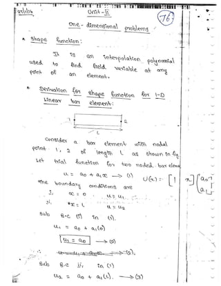
  • 142. R.M.K COLLEGE OF ENGG AND TECH / AQ / R2013/ ME6603 / VI / MECH / JAN – MAY 2017 FINITE ELEMENT ANALYSIS QUESTION BANK by ASHOK KUMAR.R (AP / Mech) 61 2.209) Derive the interpolation function for the one dimensional linear element with a length “L” and two nodes, one at each end, designated as “i” and ” j”. Assume the origin of the coordinate system is to the left of node “i”. [AU, April / May - 2010] Figure shows the one-dimensional linear element