1. Electrical Testing
Electrical installation testing should only be carried out by qualified professional electricians, with the relevant
equipment - the following tests cannot otherwise be carried out.
The test procedures outlined in this page are based on a new domestic dwelling with all electrical equipment in place.
The test procedures are generally split up into two bands, 'Dead testing' and 'Live testing'.
Dead testing is, as it sounds, performed on the circuits when they are de-energized, and form the initial testing of the
circuits. These tests will outline the insulation resistance of the new circuits, and the continuity of the ring circuits.
IMPORTANT: ON EXISTING INSTALLATIONS, ENSURE ALL EQUIPMENT IS UNPLUGGED FROM THE CIRCUITS, these
tests produce high voltages and will damage some equipment. Any apparatus plugged into a circuit that is being
tested will also cause poor readings.
Tip: ensure all neon's are removed or isolated before commencing testing, as these will make test results appear low
during insulation resistance testing.
Live testing is then performed on the circuits once the results of the dead tests have been recorded as satisfactory,
and once the installation has been put back together following the dead testing.
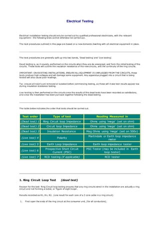
The table below indicates the order that tests should be carried out.
Test order Type of test Reading Measured in
(Dead test) 1 Ring Circuit loop Impedance Ohms using 'mega' (set on ohm)
(Dead test) 2 Circuit loop Impedance Ohms using 'mega' (set on ohm)
(Dead test) 3 Insulation Resistance Meg Ohms using 'mega' (set on 500v)
(Live test) 4 Polarity
Martindale or Earth loop impedance
meter
(Live test) 5 Earth Loop Impedance Earth loop impedance tester
(Live test) 6
Prospective Short Circuit
Current (PSC)
PSC Tester (may be included in Earth
loop tester)
(Live test) 7 RCD testing (if applicable) RCD tester
1. Ring Circuit Loop Test (dead test)
Reason for the test: Ring Circuit loop testing ensures that any ring circuits wired in the installation are actually a ring
circuit and not forming a radial, or 'figure of eight loops'.
Results recorded as R1, Rn, R2. (one result for each core of a 3 core cable in a ring circuit)
1. First open the ends of the ring circuit at the consumer unit, (for all conductors).
2. 2. Connect the live of one end of the ring to the neutral of the other end of the ring and test between the live and
neutral remaining. This tests the cables in the ring in a double loop format, to ensure the conductors form a ring
without figure of eights. Perform this test using a mega in Meg Ohms.
3. On completion of this test, remove the link and proceed to test live to live, neutral to neutral, earth to earth.
Record these results in Ohms.
2. Circuit Loop Test (dead test)
Reason for the test: Circuit loop testing ensures that any circuit wired in the installation are actually containing cables
that conduct one end of the cable to the other, without a huge resistance in its path. Result recorded as R1+ R2
1. First open the ends of the circuit at the consumer unit, (for all conductors).
2. (To record R1+R2) Connect the live end of the cable to the tester, then connect the neutral to the
tester. Ensure that at the end of the circuit (ie, at the furthest socket) that you short out the live and neutral
conductors. Perform this test using a 'mega' in Ohms. This result is R1+R2.
2a. (To record R2) To provide an accurate R2 result, instead of connecting the neutral conductor to the tester,
connect the tester to a long piece of cable with a known resistance, then connect the other end of this cable to the live
of the furthest socket in this circuit. The reading you achieve must then have the resistance of the 'known resistance
cable' deducted.
For example result = 4ohms, Known cable resistance is 1.2 ohms, therefore 4ohms - 1.2 ohms = 2.8ohms (the actual
result of R2)
3. Insulation Resistance Test (dead test)
3. WARNING : ENSURE NO APPARATUS IS CONNECTED TO THE CIRCUIT TO BE TESTED!!
Reason for the test: To ensure the insulation of the cable has not been damaged, and has no faults present. Results
recorded in Meg Ohms
Connect the test probes to the live and neutral of the cable that requires testing, then test!! Repeat the procedure
between the live and earth, and the neutral and earth.
Notes: Neon's will cause false readings, as will emergency or discharge lighting, so ensure these are all disconnected
prior to commencing tests.
4. Polarity Testing (live test)
Reason for this test: to ensure apparatus connected to the circuit is connected correctly, and does not become
damaged. Results shown by indicators on tester.
Plug in tester, and ensure the polarity is correct according to the charts on the test instrument. (Varies from tester to
tester)
5. Earth Loop Impedance Test (live test)
Reason for test: To ensure the resistance of the earth cable is not so high as to prevent it from working correctly in
the event of a fault.
Please note the chart below, which is intended as a guide for the Maximum Earth Loop Impedance permitted by the
current regulations.
To perform the test plug in the instrument, set the range to the lowest setting first and press test, then record the
result (if over range turn the testers range up to the next setting and repeat the test).
MCB
Rating
Type 1
MCB
Type 2
MCB
Type B
MCB
Type C
& 3
MCB
Type D
MCB
6 8.0 4.56 6.4 3.2 1.6
10 4.8 2.74 3.84 1.92 0.96
16 3.0 1.7 2.4 1.2 0.6
20 2.9 1.36 1.92 0.96 0.48
32 1.5 0.85 1.2 0.6 0.3
40 1.2 0.68 0.96 0.48 0.24
63 0.76 0.43 0.6 0.3 0.15
BREAKERS DIFFERING FROM THOSE SHOWN- ie.5 & 30amp (Crabtree C50) ARE NOT THE SAME READINGS AS
INDICATED.
Allows for both 0.4 & 5.0 second disconnection times. Based on 230volt system.
These values are Zs values found in tables 41B1, 41B2 & 41D of the regs.
6. Prospective Short Circuit Test (live test)
4. Reason for the test: To ensure that in the event of a short circuit, the cable tested can carry enough fault current, to
trip the MCB or blow a fuse, as quickly as possible (and within the stated regulation guideline times of 0.4 seconds for
socket outlets (portable equipment) and 5 seconds for fixed equipment).
Plug in the test equipment and press test, the higher the result the better.
Result should be recorded in hunderds of amps.
7. Residual Current Device Test (live test)
Reason for the test: To ensure that the RCDs installed will trip fast enough in the event of a fault, to prevent
electrocution.
Plug in test equipment (set at the rating of the RCD), and set the test at 0.5 of the RCD's rated tripping current - the
RCD must not trip out.
Repeat the test at the rated tripping current of the RCD, the device should trip out in around 0.3 of a second.
Repeat the test again, setting the test at 5 times the rating of the RCD, the RCD must trip faster than the last result
(even though only slightly).
For full details on tripping times, refer to the 16th Edition of the IEE wiring regulations.
Test sequence and descriptions
The followingtests are carried out with the Consumers main switch isolated
1. Extenal earth fault loop impedance
Reason: To establish thata good earth exists atthe installation in order for the remainingtests to go ahead.
Method: Disconnectthe main earthing conductor from the main earthing terminal.An earth faultloop
impedance tester is connected atlineand earth (main earthing conductor) at the supply sideof the installation
and a test performed. Reconnect the main earthingconductor. The resultis Ze and recorded on the sheet. The
prospectivefaultcurrent is measured at the same time after the reconnection of the main earthing conductor.
2. Continuity of protective and bonding conductors
Reason: To check that all circuitprotectiveconductors (green and yellow cables) arecontinuous and are
present at every electrical accessory on the circuit.Also to check that the main earthingconductor and main
bondingconductors are continuous and correctly connected.
Method 1: The lineconductor is connected to the circuitprotective conductor of the same circuitatthe
5. consumer unitand a measurement taken at ALL accesories on thatcircuitbetween lineand c.p.c. The highest
measurement obtained is recorded on the test report.
Test resultis R1 + R2. The lineconductor and neutral conductor are then connected and the above repeated to
obtain R1 + Rn
Method 2 (used for main earth and main bondingconductors): A wandering lead is connected to one end of
the conductor to be tested and a measurement taken between the other end of this lead and the other end of
the conductor.
Test resultis R2.
Duringthis test polarity can bechecked as well.The continuity of the neutral conductor can also be checked.
3. Continuity of ring final circuit conductors
Reason: This test ensures that all ringfinal circuits(sockets usually) areindeed a continuous ringwi th no
interconnects or breaks within it.
Method: The line,neutral and earth conductors of the circuitareidentified and a measurement from one end
to the other end of each is taken. These results arer1, r2 and rn.
The incominglineconductor is then connected to the outgoing earth conductor and the outgoing line
conductor is connected to the incomingearth conductor. A measurement is then taken at ALL socket outlets
on the ring. The highestof which is recorded on the report.
This resultis R1+R2 for that circuit.The above is then repeated usingthe neutral conductor instead of the
earth conductor. This test provides R1+Rn which does not need to be recorded on the report but is essential to
check the circuitcorrectly.
4. Insulation Resisitance
Reason: This test checks whether the insulation around a cableis still intactand has notbroken down over
time. It is a good indicator of the age of an installation.
Method: An insulation resistancetester is connected across lineand neutral tailsatthe origin of the supply.
500V are then pumped down the conductors to see if any voltage leaks across fromone conductor to the
other. The same is then done for the lineand earth and the earth and neutral conductors.
5. Polarity
Reason: To check that all accesories arecorrectly connected to line,neutral and earth and that all switches and
circuitbreakers areconnected in the lineconductor only.
Method: The method for this is the same as for continuity and is usually doneatthe same time by operating
switches etc whilstconductingthe test.
6. Earth electrode resistance
6. Reason: To make sure that any earth electrode used is of a sufficiently lowimpedance to allowthe timely
operation of the RCD protecting the installation.
Method: An earth fault loop impedance tester is connected between lineand earth at the origin of the supply
and a test performed. The resultof which is considered the resistanceof the electrode (Ra).
The followingtests are carried out with the Consumers main switch energised
7. Live polarity test
Reason: To verify polarity of supply authorities system.
Method: An approved voltage indicator shall beused or test lamp to GS38. Usingthe approved voltage
indicator,oneprobe shall beplaced on the incomingneutral,and the other on the incominglineconductor,on
the main breaker. The indicator should showitis live.One probe shall nowbe placed on the CPC and the other
on the incominglineconductor. The indicator should showitis live.A test shall bepreformed between CPC &
incomingneutral.The indicator should showthatit is not live.
8. Earth fault loop impedance
Reason: This test is done at the furthest point on a circuitin order to make sure the impedance of the earth
path is not too high even at the furthest pointso that sufficientcurrentwill flowunder faultconditions to take
out the circuitbreaker protecting the circuit.
Method: An earth faultloop impedance tester is connected to lineand earth at the furthest point on the
circuitand the test performed.
9. RCD test
Reason: To make sure RCD's trip within the correct time
Method: An RCD tester is connected and a test at1/2 times, 1 times and 5 times the trip current is performed
on each sideof the cycleand a time of trip obtained. Usually milli-secondswith the highest being recorded.
The manual test button is then pressed.
10. Functional testing
7. Reason: To make sure all switches,isolators,MCB's etc. work as they should.
Method. Self explanatory.