Project Report -Trainee Engineer At Diesel Locomotive Shed, Indian Railways
1. 7/20/2015
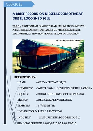
A BRIEF RECORD ON DIESEL LOCOMOTIVE AT
DIESEL LOCO SHED SGUJ
TOPIC: - REPORT ON AIR BRAKES SYSTEMS, ENGINE BLOCK SYSTEMS,
AIR COMPRESSOR, HEAT EXCHANGER, GOVERNOR, ELECTRICAL
EQUIPMENTS, AC TRACTION MOTOR-THEORY OF OPERATION
PRESENTED BY:
NAME : ADITYA BHTTACHARJEE
UNIVERSITY : WEST BENGAL UNIVERSITY OF TECHNOLOGY
COLLEGE : BUDGEBUDGEINST. OF TECHNOLOGY
BRANCH : MECHANICAL ENGINEERING
SEMESTER : 6TH
SEMESTER
UNIVERSITY ROLL NO: 27600712006
INDUSTRY : SILIGURI DIESEL LOCOSHED SGUJ
TRAINING PEROIOD: 24/06/2015 TO 14/07/2015
2. ACKNOWLEDGEMENT
I am using the opportunity to express my gratitude to everyone who supported
me throughout this training. I am thankful for their aspiring guidance,
invaluable constructive criticism and friendly advice during project work. I am
sincerely grateful to them for sharing their truthful and illuminating views on a
number of issues related to this project.
I expressed my warm thanks to DME Mr. S Gupta, Mr. B K
Majumdar and Mr. Sushanta Barman for his support and guidance at Indian
Railway.
I would also like to thank my project guide Mr. Tapan Nandy ,Mr.
Tapas Sarkar, Dipankar sir, Basak Sir and Mr. D Barman from the Indian
Railway and all the people who provided me with the facilities and conductive
conditions for this project.
ThankingYou,
AdityaBhattacharjee
3. CONTENTS
ACKNOWLEDGEMENT
WORKING PRINCIPAL OF TWO STROKE DIESEL ENGINE
COMPARTMENTS OF GM LOCOMOTIVE
GM LOCOMOTIVE SPECIFICATION
COMPRESSED AIR SYSTEM
AIR BRAKE SYSTEM
SAFETY DEVICE
TRACTION ALTERNATOR, COMPANION ALTERNATOR,
AUXILARY GENERATOR, TRACTION MOTOR MAINTANACE
TROUBLE SHOOTING MECHANICAL PROBLEMS
CONCLUSION
4. GM LOCOMOTIVE DIESEL ENGINE
DUEL CAB LOCO
SINGLE CAB LOCO
NOSE
COMPT
CAB 2 RADIATOR
COMPT
COMPRESSOR
COMPT
ACCESSORIES
COMPT
ENGINE
COMPT
ALTERNATOR
COMPT
TCC 1 & 2
CENTRALIZED AIR
FILTER COMPT
CAB 1
SIDE VIEW OF GM LOCOMOTIVE
LUBE OIL
STRAINER LUBE OIL
SCAVENGING PUMPMAIN LUBE OIL CUM
PISTON COOLING PUM
WATER
PUMPS EXHAUST MANIFOLD
CAMSHAFT,
VALVE
LEVERS
INSIDE
ENGINE
CRANKCASE
ENGINE BLOCK
CRANK
CASE
COVER
AIR BOX
COVER
TWO STROKE DIESEL ENGINE
5. Working Principle – Two Stroke Diesel Engine
In two stroke Diesel engine cycle is completedin two stroke of the piston that is, in one
revolution of Crankshaft.
During downward motion of piston
1. Fuel injection when piston is in TDC
2. Power
3. Exhaust (exhaust vales are in open condition)
4. Scavenging (Exhaust valves are remainedopen + Inlet ports in the wall of cylinder liner
are opened when piston circumferential wall comes below intake ports of liner)
During upward motion of piston
1. Scavenging (both exhaust valves and inlet ports are in opened position)
2. Exhaust (exhaust valves are remained open, intake ports are closed by piston wall)
3. Compression (after closing of exhaust valves)
Diesel Engine Terminology
TDC – Top Dead Centre
BDC – Bottom Dead Centre
6. Combustion Space – Clearance space in between TDC and cylinder head
Stroke Length / piston displacement – Distance in between TDC to BDC
ENGINE COMPONENTS
1. Engine Block (Cylinder liners inside)
2. Cylinder Heads
3. Crankcase
4. Pistons
5. Inlet Valves (four stroke engine) / Intake ports ( two stroke engine)
6. Exhaust Valves
7. Valve Levers (Valve actuation mechanism)
8. Fuel Injection Pumps and Injectors / Mechanical Unit Injector(MUI) in GM Loco
7. 9. Pistons Connecting Rods
10.Crankshaft
11.Camshaft
12.Oil Sump (Bottom end of the crankcase)
CYLINDER IDENTIFICATION
ENGINE RELATED SYSTEMS
1. Fuel oil system
2. Compressed air system
3. Engine Lube Oil system / Engine lubricating system
4. Engine Cooling Water system
5. Booster Air system / Turbo-charging (An additional system to increase power of
heavy duty multi-cylinder Diesel engineprovidedinRailway Locomotive) or Charged
air system
6. Air brake system
8. GM LOCOMOTIVE COMPARTMENTS
1. NOSECOMPARTMENT:
(a) CCB (computer control brake) air brake equipment panel.
(b)CRU (computer relay unit). VFD is fittedwithCRU.
(c) Dead engine cut out cock (it is openat vertical position).
(d)PCU (Pneumatic control unit)
2. DRIVERS CAB:
(a) Control stand: - 2 Nos
(b) Reverserhandle
(c) Automatic brake valve with5 positions (Release, run, minimumservice, full
service &emergency)
(d) Independent brake handle withthree positions (quick release, Release &
Application).
(e) Air brake Lead/Trail setupswitch(like MU-2B) with4 positions.
i] Lead (in working control stand)
9. ii] Trail (in non-working control stand)
iii]Test (During load (coach/wagon) attachment.
iv] HLPR (inbanking loco)
(f) Reset (alertness control) pushbuttonswitch.
(g) Manual sanding switch
(h) Horn pushbutton switches.
(i) Headlight switches
(j) Duel Gauge for MR & ER, Duel Gauge for BP & BC, Air FlowIndicator
(AFI), Speedometer, TractiveEffort meter (TE)
(k) Indicator Panel switchfor Sanding, Flasher light, Brake warm, PCS, Wheel
Sleep.
Note- engine run, Cont-F.P, G.F. sliding switch, M.U. Run / Stop switch,
Dynamic Brake circuit breaker they are only control stand-2.
3. ELECTRICAL CONTROL CABINET(ECC-1) :
(a) Circuit breaker panel.
10. (b) Engine control panel (isolationswitch, EFCO, prime/startswitch,
classificationlight switch, dynamic &blendedbrake switch)
(c) Circuit breaker and test panel.
(e)Computer display panel ( EM-2000, LCC, EMD)
4. TRACTION CONTROL COMPARTMENT(TCC):
(a) Tractionmotor computer & inverter.
(b)Dynamic braking Grid and Blower fan.
(c) IGBT or GTO / DCL
(d)TCC blowers. .
5. CENTRALIZED AIR FILTER COMPARTMENT-
Consists of following components-
a. Inertial air inlet filters/cyclonic filter at the bothside of walls
b. Dust bean blower
c. Tractionmotor blower.
d. Alternator cooling blower.
e. Engine intake filter (Baggies type).
f. Crow bar (IPR).
11. g. Rader magnet valve.
h. Rectifier bends.
6. TRACTION GENERATOR COMPARTMENT:
(a) Eductor assembly.
(b)Tractiongenerator with companion alternator.
(c) Turbo super charger (EMD ‘G’ series) withtwoNos. after cooler.
(d)Auxiliary generator.
(e)Engine starting motors (twoin no).
7. ENGINECOMPARTMENT:
a. 2-stroke, 16-cylinders, V-type, turbo-chargedengine.
b. Battery knife switchandfuse are providedat engine rear end right side (Loco’s
left side).
c. Turbo lube oil pump (soak back pump) is providedat the engine left side (loco’s
right side).
d. Lube oil dip stick gauges are providedon both left and right banks of the engine.
e. Soak-back & turbo-spinon filter.
12. 8. ENGINEACCESSORIES COMPARTMENT:
a. Wood word governor(PGEV)
b. Water pumps (2nos) for left and right banks.
c. Governor booster pump.
d. Scavenging pump: draws oil from lube oil sump through scavenging strainer and
supplies to main lube oil pump through oil filter and cooler.
e. Main lube oil & piston cooling pump: for piston cooling and engine lubrication.
f. Lube oil strainer housing.
g. Maciana filter housing consists of 5 paper type filter elements.
h. Lube oil cooler
i. Engine water tank.
j. Fuel primary filter.
k. Fuel pump (at engine right bank).
l. Enginemountedfueloil secondaryfilters(twoinnos.) spin-ontypewithsightglasses
provided on engine right free end side.
m. EPD (engine protection device) provided on engine left side.
Low lube oil protection device.
Low water level /pressure protection.
13. Crank case vacuum protection device.
OSTA (over speed trip assembly)
HOD (Hot oil detector)
n. Fuel prime/start switch, provided at the left side of engine equipment rack. (in
WDG4) Hand brake on left side of engine accessories compartment.
9. COMPRESSOR COMPARTMENT:
a. 2 stage, 3 cylinders Air Compressor (cooledby engine cooling water system).
b. MVCC (magnet valve for compressor control).
c. Sanding magnet valve (02 no).
d. Horn magnet valve (01 no).
e. EBT (exust blowdown timer).
f. Inter-cooler.
g. Inter-cooler safety valve.
h. MRPT-cut out cock.
10.RADIATOR COMPARTMENT:
a. Radiator core (two nos.) locatedon headers on top of the cooling fans.
14. b. Two radiator cooling fans (AC motor driven).
c. Main reservoircooling coils.
d. compressor air intake filter.
GM LOCOMOTIVE SPECIFICATIONS
1.TYPES OF GM LOCO: WDG-4 / WDP- 4, WDP- 4 B, WDP- 4D (Duel Cab)
Nominal Locomotive Power:4000 HP / 4200 HP / 4500 HP
2.DIESEL ENGINE
Number of Cylinders:16
Engine Type: Two-Stroke, Turbocharged
Cylinder Arrangement:45° “V”
CompressionRatio:16:1
Displacement per Cylinder:11 635 cm3 (710 cu.in.)
Cylinder Bore:230.19 mm(9-1/16”)
Cylinder Stroke:279.4 mm(11”)
16. MaximumVoltage:230 VAC
Frequency at 904 RPM:120 HZ
MaximumPower: 250 KVA (Power factor 0.8)
AUXILIARY GENERATOR
Model:5A-8147
6.RECTIFIED OUTPUT RATINGS:
Nominal Voltage:74 volts DC
MaximumPower: 18 kW
TRACTION MOTORS
Model:Siemens 1TB-2622-0TB02
Quantity:4 (2 in parallel per bogie WDG-4), 6 Nos. in WDP-4
Type: 3 Phase AC Induction,
Nominal Ratings:500 KW, 2027 VAC, 3220 RPM
7.TRACTION INVERTERS (TractionControl Converters TCC1, TCC2)
Rating:1430 KW
17. Quantity:[(one per bogie (truck)]
Type: Voltage Source Inverter withGTO/IGBT
BOGIES
Model:HTSC
Gear Ratio: 77:17 in PAC / 90:17 in MAC
DRIVING WHEELS:
Quantity:2 PoweredWheel Sets per bogie –WDP- 4 (1 Non-poweredWheel Set per bogie
i.e.truck)- -, BO- 1 – 1- BO
3 PoweredWheel Sets per bogie (WDG- 4) – CO-CO type bogie.
Diameter:1092mm(43 inches)
BRAKERIGGING:
Type: Single Shoe
Shoe Material: Composite
Brake Cylinders:4 per bogie {truck}
0
18. -:AIR BRAKECONTROL SYSTEM:-
KNORR CCB Equipment
1.AIR COMPRESSOR:
Model:WLNA9BB
Type: Two Stage, 3 Cylinder
Coolant: Engine Coolant
Displacement at 900 RPM:7.19 M³/Min(254 Cu.Ft./Min.)
Sump Lube Oil Capacity:9.98/11.63 Liters
2.LOCOMOTIVESTORAGEBATTERIES
Arrangement:2 Series-connected16-Cell, Nickel –Cadium
Total Quantity of Cells:32
Total Potential of Batteries:64 Volts
19. Specific Gravity of Electrolyte:1.250
8 hour Capacity:500 Amp. Hr.
3.SUPPLIES/CAPACITIES:
Fuel Capacity:6000/5000lit
Lube Oil SystemCapacity:1457 Litres
Cooling SystemCapacity:1045 Litres
Sand Boxes (8) Capacity:0.04cubic meter per box
Governor oil capacity: 650/700 ml
Gear-case oil capacity:8.5 lit (WDP-4)
7.5 lit (WDG-4)
Axle Load- --------21.5 Ton(WDG 4).
Loco Weight- 126.010Ton.
Loco Height- 4.61 meter.
Loco Width- 3.07 meter.
Loco Length- 21.24 meter.
20. ECC – 1 Circuit Breakers
1. Yellow Leveled Circuit Breakers-
a. Computer circuit breaker
b. Turbo circuit breaker
2. White LeveledCircuit Breakers-
a. Governor booster pump circuit breaker
b. Air dryer circuit breaker
c. Event recorder
d. Light and cab fan
3. Black LeveledCircuit Breakers-
a. AC control breaker
b. Control breaker
c. Local control
d. Filter blower motor
e. GTO - 1 & GTO – 2 / IGBT – 1 & IGBT – 2 (DCL 1 to 6 incase of MEDHA based
computerizedsystem)
f. Auxiliary generator fieldbreaker
g. Fuel pump circuit breaker
h. TCC – 1 & TCC – 2 computer breakers (TC 1 to 6 in case of MEDHA based
computerizedsystem)
i. MAB (Microair brake) circuit breaker
j. TCC Blowers circuit breaker 1 &2 (1 to 6 in MEDHA)
k. G.F. Circuit breaker
ENGINE STARTING PROCEDURE OF WDP 4 /WDG4
1. Put ON Battery Knife switch.
2. Put “ON” all Black leveled, White leveled Circuit breakers in ECC- 1. Check yellow
level Computer and Turbo Soak back pump circuit breakers, these should be
21. remained “On”
3. Put On sliding switches in Control Stand – 2 (Engine Run, FP & Control, latter GF
before Run).
4. Put Isolation switch is in Isolate position.
5. Keepthe enginestartswitchtothe“Primeposition”(left)forapprox 15 secthenturn
the Engine Start switch to “Start position” (right ) till engine taken .start
(Until engine RPM is above 160)
6. Do not shift the Isolation switch to “Run” position immediately after cranking to
avoid Automatic shut down of engine due to low water and low lube oil pressure.
7. In EM2000 screen display, Press Crew for any active crew message.
8. In case air brake penalty is occurred just after starting, recover penalty by putting
Auto Brake handle in full service (FS) for 10 Sec.
ENGINE SHUT DOWN PROCEDURE OF WDP 4 / WDG4
1. Put Reverser handle to centre position and Throttle idle position.
2. Put engine run switch and GF switch to “Off” Position.
3. Put Isolation switch to Isolation position.
4. Press Emergency cut off switch till the engine gets shut down.
5. Put off all White and Black labels circuit breakers except yellow labeled Turbo and
Computer control circuit breakers.
6. Put Off all sliding switches in Control stand- 2 (GF, Engine Run, FP & Control).
22. 7. Put off battery knife switch.
8. Apply Hand Brake.
PROCEDURE FOR CHANGE OF CONTROL STAND
To convert the working control stand into non- working control stand-
The following steps are to be carried out in the same sequence.
A. Throttle to be in idle.
B. Bring Reverse handle to Neutral and remove the handle.
C. Autobrake handle to be moved to full service andlocoindependent brake handle to be
moved to release position.
D. After brake cylinder pressure stabilizes at 65 PSI and brake pipe pressure stabilize at 50
PSI, lead/trail switch to be pressed and moved to trail position.
To convert non-working control stand into working control stand-
A. Reverser-handle to be inserted and positioned in centre (Neutral position).
B. Throttle to be in idle.
C. Auto brake handle should be moved to run position.
D. Loco independent brake handle to be moved to full application position.
23. E. Lead / Trail switch to be pressed and moved to lead in position.
CAB CHANGING PROCEDURE OF DUEL CAB GM LOCOMOTIVE
Procedure for Working to Non-Working control standinDuel Cab GM Loco
i. Secure the Locomotive properly.
ii. Throttle handle Idle.
iii. Reverser handles neutral andremoves.
iv. AutoBreak Handle is in FS Position.
iv. Direct Break Handle is inRelease Position
vi. Lead-Trail switchis inTRAIL Position
a. Loco with MEDHA basedcomputerizedsystem:
i. Put “Off” Gen fieldcircuit breaker inECC.
24. ii. Put “Off” Gen Fieldsliding switch, Engine Runand Fuel pump control sliding
switches inControl stand.
b. Loco withSIEMENS based computerizedsystem:
i. Put “Off” Gen Fieldcircuit breaker inECC, Fuel pump control sliding switchand
Gen Fieldsliding switchinControl Stand (Engine RunswitchremainedON..
(NB: - FUEL PUMP SLIDING SW. PUT ON WITHIN 10 MIN.IN WORKING CAB in Medha based
system.)
ii. BL Key Switchis to put OFF and Removed.
Procedure for Non-Working toWorking control stands in Duel Cab GM Loco
i. Insert BL Key and put it ON.
ii. Put “On” Engine Run and Fuel pump control sliding switchesinControl standinMedha
basedcomputerizedLoco.
iii. Put “On” GenFieldsliding switchbefore running of loco
In case of locowithSiemens computerizedsystem, put “On” GenFieldcircuit breaker in
ECC and GenFieldsliding switchinControl Standonly.
iv. Insert Reverser handle (throttle handle Idle).
v. AutoBreak Handle is inReleasedposition
25. vi. Lead-Trail switchis inLead position
PROCEDURE FOR DEAD LOCO (WDP 4 / WDG4) ATTACHMENT WITH WORKING (WDP 4 /
WDG4) OR WDM- 2
1. DrainMR-Iand MR-IIreservoirs&openBCEQ pipesonesideof thelocomotive.
2. Switch off the all breakers
3. Open dead engine cut-out cock.
4. Keep Lead/Trail switch in Trail position.
5. Couple BP hose and open angle cock to charge brake pipe.
PROCEDURE FOR ATTACHMENT OF LOCO (WDP 4 / WDG4) WHICH IS NOT IN SHUT DONE
CONDITION (NOT AS MU OPERATION)
1. Keep isolation switch is in isolate position.
2. Keep Lead/Trail switch is in Trail position of both control stands.
3. Couple BP hose and open angle cock to charge brake pipe.
26. PROCEDURE FOR DEAD LOCO (WDM- 2) ATTACHMENT WITH GM LOCO
1. DrainMR-I and MR-II reservoirs, feedpipe, MR equalizing andBrake cylinder pipes.
2. Switch off the all breakers
3. Close 3 /4th COC near control stand No- 2.
4. Keep Lead/Trail switch in Trail position.
5. Couple BP hose and open angle cock to charge brake pipe.
EM-2000 Introduction
The locomotive computer display panel keypad. It is equipped with 16 keys.
1. F1, F2, F3, F4 Keys – Functional Keys. Pressing a function key typically requests the
locomotive computer to perform a function such as:
2. Reset a fault, Cut out an inverter, Display stored data, etc.
3. ON / OFF Key controls display panel operating power.
4. MAIN MENU Key returns screen to main menu.
5. BRIGHT/DIM Key controls screen intensity.
6. HE POWER Key Not used.
7. ARROW Keys move the screen cursor.
27. 8. SELECT Key selects the item at the cursor location.
9. CREW Key returns screen to crew messages display.
FUEL OIL SYSTEM
Fuel from fuel tank is drawn by the fuel booster pump throughsuctionstrainer. Fuel from
suction strainer flows to fuel booster pump. Pressurized fuel from fuel booster pump is
then goes to fuel primary filter and then goes to secondary filters.
A bye pass valve and gauge is provided withfuel primary filter toprevent overloading fuel
boosterpump incaseof chockedfuel filter.Thebye pass valve issetat 30psi and the gauge
having Green, Yellow and Red Zones.
FuelfromsecondaryfilterenterstofuelheadersA reliefvalveisprovidedbeforesecondary
filters which is set at 65 PSI and in case of chocked secondary filter, fuel is returnto fuel
tank by opening relief valve. A glass cover provided withthe relief valve indicates the bye
passed fuel flowing back to diesel tank.
Fuel flown to both bank fuel supply headers, enters individual fuel injectors through the
fuel lines.
The excess fuel from injectors flow back to fuel return headers and to fuel tank through
fuel regulating valve set at 15 PSI. As like relief valve, regulating valve is alsocovered by a
sight glass bowl. Both regulating and relief valves are placed over the fuel spin on filters.
29. The systemconsiststhe following:
a. Exhaust manifold
b. Turbo supercharger
c. Turbo clutch
d. Baggie filters
e. After coolers
The Turbo Charger is used to increase engine horse power. Turbine of TSC is rotated by
engine exhaust gas. Attachedblower withturbine is also rotatedand supplies pressurized
air to engine cylinders. As available total quantity of pressurizedair is much higher (than
air intake in natural aspiratedengine) so, it is possible toinject more fuel and thus engine
power is increased. This pressurized air is called as Booster air.
In GM locomotive, rotor assembly (Turbine andblower attachedwithrotor shaft), initially
rotated directly by engine shaft and from 6th Notch, full load (Exhaust gas temperature
1000 degree Fahrenheit), it is driven by exhaust gas. An overrunning clutch assembly
(freewheeling device) is provided for this change in blower driving system
30. Two stroke engine has no separate suctionstroke like four stroke engine and pressurized
air is not available until turbine rotates at high speed. So, such arrangement of blower
driven mechanism is provided so that, blower supplies sufficient air during intake phase
even exhaust gas pressure is low.
LUBRICATING OIL SYSTEM
By pass valve
with gauge 40
psid
31. Lube oil systemconsists of Engine sump, scavenging pump, Main lube oil pump, Lube oil
strainer housing, Filter assembly, Turbo oil filter.
Oil from the engine sump is drawn by gear driven scavenging pump through a
coarse(rough) mesh lube oil strainer element is filtered in lube oil filter tank wherein 5
32. filter elements are fitted. Fromthe filter tank, oil withpressureis suppliedtomainlube oil
pump through lube oil cooler and fine mesh lube oil strainer elements. A lube oil valve is
providedacross lube oil filter tank set at 40 PSI. This valve is responsible for continuous oil
supplytoenginemoving partsevenduringfilterschoke.Afilterconditiongaugeisprovided
across filter tank &is inparallel withbye pass valve toindicatethe lube oil filters condition
continuously.
Pressurizedlube oil supply by scavenging pump is further pressurizedby a main lube oil
pump on a single drivenshaft having two pumps, one for pistoncooling and the other for
all main bearings andother engine moving parts. Pistoncooling pumpsuppliespressurized
oil toall the pistons throughcooling headersonthe bothbanks and throughpistoncooling
pipes. This cools the piston crown from bottom and lubricates cylinder liners and piston
rings while flowing down to the sump.
Pressurizedoil from main lube oil pump passes through a pressure relief valve set at 125
psi, lubricate all main Bearings, connecting rodbearings, bothendengine gear trains, stub
shafts, all cam bushes through drill oil passage in cam shafts, valve lever mechanism.
Oil pipe line from the cam gear end lube oil main header is taken to engine Governor to
shut down the engine in order to protect the engine under low oil pressure.
Turbo Soak Back Pump-
55 V AC Electrical Motor (3/4 HP) driven pump circulates engine lube oil to turbo before
cranking the engine and after shutting down the engine to protect the turbo running
without oil and to cool turbo after engine is shut down.
Working time of this turbosoak back pump is controlled by EM 2000. The time periodis 15
minutes if loco was working below 4th. Notch and 35 minutes above 4th.Notch before
shutting down.
34. 1 - Engine Block
2 & 3 - Water Pump
3 - Expansion tank
5 & 6 - Radiators
7 - Radiator Vent pipes
8 - Lube oil Cooler
9 - Air compressor
10 - Water drain cock
11 & 12 - After Coolers
13 - Inter Cooler
The hot water in the radiator is cooled through two AC motor driven Radiator Fans
poweredfromCompanion Alternator. Thesefans are controlledby EM 2000 withtwofeed
backs from Temperature Sensors (ETP1&ETP2).
35. The Radiator Fangets three phase AC supply fromCompanion Alternator through3 setsof
Contactors for each Fan. FCS (Fan Contactor Slow) for half speedand FCFA and FCFB (Fan
Contactor Fast) for full speed. The systemmaintains the coolant temperature between79
deg. C and 87 deg. C.
If, EM 2000 detects the failure of the Temperature sensors, it displays a Crew Massage
“Engine Temperature Feedback”failure andstores the massage in the Archive Memory. If
it detects both sensors have failed, engine goes back to idle and following massage is
displayed “No Load - Engine Temperature Feedback Failure”.
If for any reasonone Radiator Fanmotor is not working the coolant temperature willraise,
when it goes above 97 Degree Celsius, then the following massage “HP is limitedto 6th.
Notch will be displayed, “HOT ENGINE” Throttle 6 limit- even if the throttle is on 7 or 8th
notch, till Temperature reaches the safe limit.
COMPRESSED AIR SYSTEM
36. The air compressorusedon WDG4/WDP4locosistwostageair compressorhaving twolow
pressure cylindersand one high pressure cylinder. The compressor is mechanically driven
by dieselengine,connectedtotheenginethrougha shaftequippedwithflexible couplings.
The compressor has a sump for lubricating oil of capacity 9.98 liters. It is equippedwithits
owninternaloilpump withreliefvalveandan oil filter.Theoillevelischeckedwhenengine
is running using a dip stick mounted on the side of the compressor crank case.
Air is suckedthroughtwodry filters (Pamic filters) intothelowpressurecylindersandthen
passedtointercoolertocool downthe compressedairtemperature.AnIntercoolersafety
valve is providedavoid damage of intercooler tubes incase high air pressure is generated
inthe tubes. After intercooler, compressedair is enteredintohighpressurecylinder where
it is further compressed and supplied to main air reservoirs.
To control the air pressure withinthe operating pressure range, an un-loader assembly is
provided on the compressor to maintain the requiredair pressure. The un-loader valves
are operated by a MVCC (Magnet Valve Compressor Control). This valve is controlledby
the EM 2000 according to pressure of the MRPT (Main Reservoir Pressure Transducer).
When the Pressure of MR. reaches 9.65 kg/cm², the MVCC is energizedby the EM 2000,
and pressurizedair from air reservoir goes toun-loader assembly and pressedinlet vales
to remain opened (unloading phase). When the air reservoir pressure reduces to 8.2
37. kg/cm², the MVCC is de-energized and trapped air in un-loader valve exhausted to
atmosphere through MBCC and again the compressor starts compressing air.
AIR BRAKE SYSTEM
The loco is equippedwith KNOOR/NYAB CCB system. This systemis an electro-pneumatic
micro processor based system. The CCB is mounted on a brake rack on the short hood
(Front) of the Locomotive.
Main Components of CCB Brake System
1. Brake Bay Rack
2. Brake Valve Controller (BVC) - Consists of automatic (A9) and Independent Brake
System (SA9) controllers.
3. Pneumatic Control Unit (PCU)
4. Computer Relay Unit (CRU)
The Auto Brake Handle has Five Positions:
HANDLE POSITION BR PIPE PR BR CYL PR
1. Release (Over Charging) 5.7 kg/cm² 0
2. Run 5.2kg/cm² 0
38. 3. Minimum Reduction 4.7 kg/cm² 0.3-0.4 kg/cm²
4. Full Service 3.4 kg/cm² 1.82 kg/cm²
5. Emergency 0 1.82 kg/cm²
BCEQ=3.5 kg/cm²
The Independent Brake Handle has 3 Positions:
HANDLE POSITION BRAKE CYLINDER PRESSURE
1. Quick Release 0
2. Release 0
3. Full Application 5.2kg/cm²
BAIL OFF/QUICK RELEASE:
39. Whenan Automaticbrakeis appliedliftingthe bail off ring providedondirectbrake handle
release brake cylinder pressure of the loco to zero.
During emergency braking BAIL OFF will not work for releasing the Loco Brake.
UNDER GEAR - HTSC (high tensile steel casting) BOGIE
40.
41. The GM Locomotive is equipped with HTSC (High Tensile Steel Cast) truck.
The truck is equipped withthree AC PoweredTraction Motors in MAC & two AC powered
Traction Motors in PAC locos.
The motors are fittedwith pinions (17 teeth in MAC and PAC) which mesh with the Bull
Gear on the axle (90 for MAC & 77 for PAC).
42. The weight of the locomotive car body is transmitted directly to the truck through four
rubber compression spring assemblies on four corners of the truck.
The truck loadis transmittedtowheel axlesthroughtwelve singlecoil spring (twofor each
journal.).
Two Nos. of heavy duty lateral absorbers are fittedin betweenbogie and super structure
(Chassis).
6 Nos of vertical shock absorbers are fitted (2Nos .at each ends) betweenbogie and axle
box.
A single is composite type brake shoe is arranged at each wheel.
UNDER GEAR – IMPORTANT CHECK-UP
a. Truck Coil Spring if found cracked.
b. In case both Journal Retainer Pins of an axle box are dismantled.
c. In case both side Vertical Dampers of same axle are dismantled.
d. In case any Yaw Damper (Lateral Damper) is dismantled.
e. If any Traction Motor Gear Case found cracked and leaking oil.
43. ENGINE PROTECTION DEVICES (SAFETY DEVICES)
1. Low oil pressure shutdown – In case engine lube oil pressure drops, Governor
low oil pressure trip plunger comes out resulting shutdown of engine.
Range - 0.8 kg per sq.cm at idle – 2.2 kg per sq.cm at 8th notch.
2. Over-speedtripmechanism – In case engine RPM raisedin betweenthe range
of 960 – 1045, over speed trip handle of the device tripped resulting fuel rack
position to No Fuel Position and engine becomes shutdown.
3. Low water pressure detector assembly – In case engine water pressure drops,
tripknob of the detector comes out andthe device shutdownthe enginethrough
engine Governor low oil pressure trip plunger.
4. High crankcase pressure detector assembly – If high pressure generates in
engine crankcase, trip knob of the detector comes out and the device shutdown
the engine through engine Governor low oil pressure trip plunger.
5. Hot oil temperature detector assembly – If by any case engine lube oil
temperatureraisedinbetweentherangeof 121to124degreeCelsius,thissensor
assembly arrange to shutdown the engine through engine Governor low oil
pressure trip plunger.
44. Low water and crankcase pressure detector assembly
Mechanical over-speed trip
45. Hot oil detector
MAR PRESSUREDROPS ON RUN
1. Check leakage in brake pipe throughair flow indicator. Alsocheck brake pipe angle
cutout cock if leaking.
2. Check leakage of feed pipe joints and feed pipe angle cutout cock if leaking.
3. Check for leakage if any, from MR equalizing and brake cylinder equalizing pipes.
4. Check “J” filter or and other drain cocks if not fully closed resulting draining of air.
5. Auto blow down valve may be continuously draining air, make it inactive.
6. Check for leakage of pipe joints near MR tanks.
7. Check for leakage of air delivery pipe joints near compressor.
8. Intercooler safety valve may be continuously blowing.
9. Air dryer passage may be choked or air dryer purge valve may be continuously
blowing. In these cases, bypass air dryer by closing air dryer circuit breaker.
10.Loco brake cylinder may be leaking (MR pressure will drop only during loco brake
operation) - Close brake cylinder COC of that particular truck.
11.In case continuous unloading which is not manageable then closed MRPT COC?
TROUBLE – AIR BRAKE SYSTEM - BRAKE PIPE PRESSURE DROPPED
1. First to check for proper MR pressure, if not take necessary action accordingly.
46. 2. Check the air flow indicator;if flow indicator needle shoots up (rise-up), it indicates
BP pressure leaking.
3. Check crew massage, if EM 2000 displays penalty, keep auto handle in FS for 10
Seconds or, Emergency for 60 seconds according to EM 2000 request.
4. After penalty time is over, andstill BP pressure not restored, keepL/Tswitchintrail
then after 10 seconds again keep in lead position.
5. If problem still exist then RE-Cycle the MAB circuit breaker for 20 seconds.
6. Even after recycling of breaker also, BP is not building, conduct Air Brake Self Test.
Recovery of Air Brake Penalty
1. Keep auto brake of working control stand in emergency or Full Service for 10 Sec. or 60
Sec. as displayed in crew massage.
2. If air brake recovery does not happen after stipulated time then .move L/T switch of
working control stand to trail and L/T switchof non working control standto Lead (repeat
this 2-3 times).
3. If then also air brake recovery does not happen then perform Micro Air Brake Circuit
Breaker Recycling.
4. If trouble still exists, perform Air Brake Self Test.
Procedure of Micro Air Brake Circuit Breaker (MAB) Recycling
47. 1. Apply the independent brake. Keep throttle handle in Idle. Keep reverser handle in
neutral.
2. Keep Isolation switch in Isolation position.
3. Switch off Computer control breaker.
4. Now Switch off MAB circuit breaker and wait for 15 sec.
5. Then first Switch on MAB Circuit Breaker then put on Computer control breaker.
Air Brake Self Test Procedure
Before running Air Brake self test verify the following:
Ensure MR pressure minimum: 8-10 kg/sq.cm.
Close BP, FP, angle cocks MR and BC equalizing cocks at both end of the locomotive also
place wooden block bottom of the wheel.
Put Isolation switch is in Isolate position.
ON WORKING CONTROL STAND KEEP -
Throttle handle in idle position, Reverser in neutral Position.
Auto brake handle in Running and Independent brake handle in application position.
Lead/Trail switch in Lead position.
48. ON NON-WORKING CONTROL STAND KEEP -
Auto brake handle in FS position and Independent Brake handle in release position.
Lead / Trail switch in Trail position.
Run air brake self test from EM-2000.
i. Press main Manu key.
ii. Select Self test.
iii. Press F2 key to select next.
iv. Select AIR BRAKE SELF TEST.
v. Press F1 key to select continues.
vi. Wait until ‘SUCCESSFUL TEST COMPLETED, NO DEFECTS FOUND’ message appears on
the screen.
vii.. after that recover 60 sec penalty.
viii.. In case test is not successful, repeat the test from other control stand.
LOW HAULING POWER
1. Checked for brake binding through Tractive effort meter.
49. 2. In case of truck cut-out in Siemens based computerizedloco / more than one motor
cutout in Medha based loco.
3. In case of axle lock.
4. Low fuel oil pressure. It is due to returning of fuel throughfuel relief valve (secondary
filter chocked), visually check for fuel flow through relief valve glass cover.
5. Engine air intake filter (Turbo air intake filter - Baggies type filter) may too dirty
resulting blockage of engine intake air passage.
6. Any air box cover may be loose and leaking booster air.
7. Turbo-supercharger may be defective, check for thick black smoke, also check for
unusual sound.
8. Check for equal torque in each truck, if required Recycle TCC.
9. Hot engine (97 degree Celsius)- Engine comes to 6th notch, hence hauling power is
reduced.
10.If LR% is less then 100%.
11.Governor is not work properly.
NO POWER
1. GF circuit breaker in ECC panel or sliding switch in control stand (No- 2) is in “off”
position.
2. Isolation switch is not in “Run” position.
3. Engine governor Emphanol plug may be loose.
4. Aux. Gen / Companion alternator output Nil – Check for trippedcircuit breakers in
50. ECC- 1 panel or ECC- 2. Alsocheck auxiliarygeneratordriveshaftcouplingjointfailure
/ shaft broken.
5. PCS opens.
6. In case of power ground.
7. If both Truck are in disable (cutout) condition in Siemens based loco / Traction
Motors are in disable (cutout) position. .
8. In case of crow bar firing- Secure the locomotive &runagain for hard crow bar shut
down engine but do not put off circuit breakers, wait for few minutes then restart
engine.
9. TCC communication link failure – Recycle TCC circuit breakers.
LR% LESS THAN 100
1. Obstruction in Engine Governor Linkage
2. Low fueloil pressure.Itisduetoreturningof fuelthroughfuel reliefvalve(secondary
filter chocked), visually check for fuel flow through relief valve/Bypass sight glass
cover (bowl shaped).
3. Engine air intake filter (Turbo air intake filter - Baggies type filter) may too dirty
resulting blockage of engine intake air passage.
4. Any air box cover may be loose and leaking booster air.
5. Turbo-supercharger may be defective, check for thick black smoke, also check for
unusual sound.
ENGINE AUTO SHUTDOWN
51. 1. Fuel pump circuit breaker is in tripped condition.
2. Fuel booster pump stops working – In this case, there will be no fuel inside of
regulating valve glass cover (fuel may exists but no sign of fuel flow).
3. Any safety device operates. (EPD- Low water pressure detector, High crankcase
pressure detector, Governor lowoil pressure tripplunger comes out, OSToperates,
Hot oil temperature sensor operates)
ENGINE CRAKING BUT NOT TAKING START
1. Fuel booster pump not working.
2. Less oil in engine governor.
3. Governor linkage having obstruction for free movement.
4. Check mainly low lube oil trip plunger if tripped. Also check OST is in tripped
condition, Lowwater pressure tripbutton(inEPD) if comes out or incase, lowwater
pressure test cock is in open condition.
ENGINE NOT CRANKING
1. Necessary circuit breakers in ECC- 1 panel are not put in “On” position.
2. In case Isolation Switch is not in Isolate position.
3. Duel starter motor pinions are not free to rotate or in case starting motor contactor
is failed to pick-up.
4. Battery knife switch is not closed properly / in case Battery is discharged.
52. LOCKED WHEEL MESSAGE
1. Slowly run the train and check for locked axle and as a result wheel skidding, any
unusual sound like tractionmotor pinionslipping withaxle bull gear, hot axle or any
burning smell.
2. If nothing found unusual then first disable that particular motor sensor and again
bring back it to enable position and run.
3. If again locked wheel message is displayed put the sensor in disable condition
(provided you are sure there is nothing abnormality and also consult with home
shed).
CROW BAR FIRED MESSAGE IN COMPUTER DISPLAY
1. Put “Off” Isolation switch for 10 second and put it “On”
If fault not rectified then-
2. Shut the engine but do not put “Off” any circuit breaker, restart the engine.
POWER GROND
a. Power Ground – No Load due to Power
i. Avoid that particular notch in which power ground occurred.
If power ground is still persists then -
53. ii. Disable truck one by one in Siemens based computerized system loco
and make disable traction motor one by one in Medha based
computerized system loco.
b. Power Ground during dynamic brake application
Put “Off” dynamic brake slide switch on ECP panel
Also, put “Off” dynamic brake circuit breaker in control stand No- 2.
c. Power Ground during auto brake application
Put “off” dynamic brake slide switch on ECP panel.
COMPUTER DISPLAY DURING NORMAL RUNNING
IN EMD AND SIEMENS BASED COMPUTERIZED LOCO
1. Mainmenu ------- toData meter throughcurser ------- PressF-3 (Select) ------ toPower
data through curser.
Shows - Throttle, LR percentage, Torque of each truck, Main generator voltage, Rader
KP, Engine RPM.
54. TRUCK CUT-OUT
1. IsolationswitchisinIsolateposition.ReverserNeutral,ThrottleIdle,GFslidingswitch
Off.
2. Main menu ----- Locked wheel detection + Traction cut-out + Self test.--- select by
curser as required.
3. Main manu- Put Curser to Traction cut-out ------ Select (F-3) ------ throughcurser ----
Enable / Disable display of truck and truck 2 ---- Do as per need by pressing Select
(F3).
LOCKED WHEEL MESSAGE
Put Isolation switch in Isolation position. Reverser Neutral, Throttle Idle, GF sliding
switch Off.
Bring Curser to Locked wheel detection ----- Press select (F3) --- Bring Cursor to particular
Motor Sensor ----- Press F -1 for Enable / Disable.
SELF TEST
COOLING FAN SELF TEST
55. Isolationswitchis inIsolationposition. Reverser Neutral, ThrottleIdle, GF sliding switch
Off.
Mainmenuincomputer-------BringcursortoSelftest------PressSelect(F3)------bringcursor
to Cooling fan------- Press Select(F 3)------Bring cursor toAll Fantest------Message- reverser
neutral, power handle Idle, Engine is running and Isolation switch to be isolate---Select
Continue (F1)----Message- Cooling fan is ready to Run, A visual check of the fans are
necessary to verify fan rotation and speedsenses. Fan 1 turn on after Start is pressed----
Select Start (F 1)---After successful test, press End test(F 4).
AIR BRAKE SELF TEST
Isolationswitchis inIsolationposition. Reverser Neutral, ThrottleIdle, GF sliding switch
Off.
ThenMainmenuin computer-------BringcursortoSelftest------PressSelect(F3)------bring
cursor to next page (Press f 2) for Air brake self test------- Press Select (F 3)------Message-
Entry conditionto Air brake test, Refer toKNORR service manual for a list and description
of the entry conditions ----- Select continue (Press (F 1) ---- If message Successful test, No
defects foundthen Press End test (F 4)----- Penalty message- Put Autobrake in Emergency
for 60 second----After 60 second message- Put Auto brake Running.
RECYCLING OF CIRCUIT BREAKERS
1. COMPUTER RECYCLING
(In case, computer hanged / message fluctuating / any other unusuality).
56. Isolationswitch is in Isolate position. Reverser Neutral,Throttle Idle, GF sliding switch
Off.
Put “Off” Computer circuit breaker 15 second then Put it “On”. A penalty will take place
with message Put Auto brake in FS for 10 second.
2. MAB RECYCLING
((For Air brake trouble)
Isolation switchin Isolationposition. Reverser Neutral, Throttle Idle, GF sliding switch
Off.
Put “Off”Computer circuit breaker------ Put “Off”MAB circuit breaker-----After 15 second,
first put “On” MAB circuit breaker thenput “On”Computer circuit breaker. A penalty will
take place with message Put Auto brake in FS for 10 second.
3. TCC RECYCLING
(For unequal torque / TCC trouble / Low hauling)
Isolation switch in Isolation. Reverser Neutral, Throttle Idle, GF sliding switch Off.
Put “Off” Computercircuitbreaker------Put“Off”IGBT– 1 & 2 /GTO 1 & 2 circuitbreakers-
---- Put “Off” TCC circuit breakers 1 & 2. After 15 second, first put “On” TCC and IGBT /
GTO circuit breakers then put “On” Computer circuit breaker. A penalty will take place
with message Put Auto brake in FS for 10 second.
COMPUTER DISPLAY DURING NORMAL RUNNING
IN MEDHA BASED COMPUTERIZED LOCO
57. 1. Mainmenu ------- toData meter throughcurser ------- Press F-3 (Select) ------toDriver
data through curser.
Shows - Throttle, LR percentage, Torque of each truck, Main generator voltage, Rader
KP, Engine RPM.
TRUCK CUT-OUT
1. IsolationswitchisinIsolateposition.ReverserNeutral,ThrottleIdle,GFslidingswitch
Off.
2. Main menu-----Traction motor Cut-Out------press (F 3)----press Change(F 3) to
highlight the particular motor to disable------Message-TM cut-out, reverser handle
neutral, MCH idle, loco speedzero-----press enter(F 3)-----Password(12345)---press O.K
(F 3)
LOCKED WHEEL MESSAGE
Put Isolationswitchin Isolationposition. Reverser Neutral, Throttle Idle, GF sliding switch
Off.
BringCursertoLockedwheeldetection(secondpage)----pressselect(F3)----bringthecursor
to particular motor sensor-------select (F 3) to disable------put password(12345)-------press
OK.
58. SELF TEST
COOLING FAN SELF TEST
Isolation switch is in Isolation position. Reverser Neutral, Throttle Idle, GF sliding switch
Off.
Mainmenu--------bring cursor toSelf test--- ---press Select (F 3) ------put password(12345)-
-----press OK(F 3)------Cursor to Autotest--------bring cursor to Cooling fan test (next page
of auto test pages)-----Message- reverser handle centered, throttle handle idle, locois not
moving, engine temperature within range-----press select (F 3)----bring cursor to All fan
test-------press continue (F 3)----Message- check is necessary to verify fan rotation, fan- 1
start one minute after------press start (F 3).
AIR BRAKE SELF TEST
Isolation switch is in Isolation position. Reverser Neutral, Throttle Idle, GF sliding switch
Off.
Mainmenu -------bring cursor toSelf test--- ---Press Select(F 3) ------put password(12345)--
--- press OK (F 3)------Cursor to Auto test--------bring cursor to Air brake self test----- Press
Select (F 3)------Message- reverser idle, TH idle, loco is not moving, isolation switch in
isolate-------press start (F 3). If message Successful test, No defects found then Press End
test (F 4)----- Penalty message- Put Auto brake in Emergency for 60 second----After 60
second message- Put Auto brake Running.
TCC RECYCLING IN MEDHA BASED COMPUTERISED LOCO
(For unequal torque / TCC trouble / Low hauling)
59. Isolation switch in Isolation. Reverser Neutral, Throttle Idle, GF sliding switch Off.
Put “Off” Computer circuit breaker------ Put “Off” DCL (alternative of IGBT / GTO) circuit
breakers1 to 6 -------- put “Off” TCC circuit breakers 1 to 6------put off TCC Blower circuit
breakers 1 to 6.
After15second,firstput“On” TCC and DCL circuitbreakersthenput “On”Computercircuit
breaker. A penalty will take place with message Put Auto brake in FS for 10 second.
COMPUTER DISPLAY DURING NORMAL RUNNING
SIEMENS BASED COMPUTERIZED DUEL CAB LOCO
1. E- To start to computer
2. O - Main Menu – For self test, Motor cut-out, Sensor cut-out.
3. 1- Design Display- During normal Running
TURBO-SUPERCHARGER
The Turbo Charger is used to increase engine horse power. Turbine of TSC is rotated by
engine exhaust gas. Attachedblower withturbine is also rotatedand supplies pressurized
air to engine cylinders. As available total quantity of pressurizedair is much higher (than
natural aspiratedengine, i.e. without turbochargedengine) so, it is possibletoinject more
fuel and thus engine power is increased. This pressurized air is called as Booster air.
In GM locomotive, rotor assembly (Turbine andblower attachedwithrotor shaft), initially
rotated directly by engine shaft and from 6th Notch, full load (Exhaust gas temperature
1000 degree Fahrenheit), it is driven by exhaust gas. An overrunning clutch assembly
(freewheeling device) is provided for this change in blower driving system
60. Two stroke engine has no separate suctionstroke like four stroke engine and pressurized
air is not available until turbine rotates at high speed. So, such arrangement of blower
driven mechanism is provided so that, blower supplies sufficient air during intake phase
even exhaust gas pressure is low.
ENGINE GOVERNOR – PGEV GOVERNOR
The Woodward locomotive governor is an electro-hydraulic governor. It has three
sections – a basic governing section, a speed setting section and a load control system.
Function of the governor-
1. Constant speed setting according to notch through speed setting solenoids.
2. On load, governor maintain constant RPM according to notch and maintain
constantoutput at eachspeedsetting according to notchby controlling fuel supply.
3. PGEV governor has a safety device (low Lube oil pressure trip plunger) which is
actuated to shut down the engine when engine Lube oil pressure is reduced.
(Range- 0.8 kg per sq.cm at idle and 2.2kg per sq.cm at 8th notch).
4. It is control the supply of fuel at every notch, according to load of the engine &
required amount of booster air pressure.
AIR DRYER
IT IS FITTED IN BETWEEN MR-1 AND MR-2
FUNCTION OF AIR DRYER
THE DRYER REMOVES MOISTURE AND CONDENSATE FROM COMPRESSED AIR SO THAT ONLY CLEAN DRY AIR
REACHES IN ALLAIR OPERATED EQUIPMENTS AND EQUIPMENTS FUNCTIONS MORE EFFICIENTLY.
MAIN COMPONENTS OF AIR DRYER
1. PRE-COALESCER: A BOROSILICATE ELEMENT WHICH COLLECITINY AEROSOL. CONTAMINANTS.
2. DESICCANTS TOWERS: THE DESICCANT BEADS (ACTIVATEDALUMINA) WHICH EXTRACT THE MOISTURE.
3. FINAL FILTER: REMOVES ANY DUST GENERATED AFTER THE AIR HAS PASSED THROUGH THE MAIN DRYER
SYSTEM.
61. 4. HUMIDITY INDICATOR: These indicatorsreveal the air humidity level by meansof color changes within the indicators.
Blue, as seenthrough the sightglass, indicates dry air. Yellow / white indicate wet or contaminatedair.
INITIALLY WHEN COMPRESSOR STARTS- BOTH TOWER IN DEHYDRATION PHASE.
WHEN COMPRESSED AIR PRESSURE REACHED APPROX 6.9 BAR - RIGHT SIDE DRYER BEGINS TO REGENERATE
(LEFT SIDE DRYER IS STILL IN DEHYDRATING PHASE ).
APPROX ONE MINUTELATER – OPERATING CYCLE REVERSE THAT IS, LEFT SIDE TOWER BEGINS TO REGENERATE
(RIGHTSIDE TOWER IS NOW IN DEHYDRATING PHASE).
DURING COMPRESSOR UNLOADING – BOTHDRYER TOWER RETURNS TO DE-HYDRATING MODE.
AIR FLOW INDICATOR
FITTED ON THE BOTH CONTROL STAND IN FRONT OF DRIVER.
PURPOSE: PROVIDED ON LOCO TO GIVE VISUAL INDICATIONS TO DRIVER DURING
LEAKAGE IN BRAKE PIPE.
COMPONENTS:
1. AIR FLOW INDICATING GAUGE CONSISTS OF TWO POINTERS - White pointer and Red
pointer
.2. AIR FLOW MEASURING VALVE
AIR FLOW INDICATOR COMPRISES OF AN AIR PRESSURE GAUGE TYPE OF
INSTRUMENT WITH A WHITE POINTER THAT REGISTERS AGAINST A SCALE ON THE
DIAL TOGETHER WITH A RED REFERENCE POINTER ATTACHED TO A KNURLED
KNOB IT CAN BE SET MANUALLY IN ANY DESIRED POSITION.(WHERE WHITE
POINTER FINALLY STOPS AFTER BRAKE PIPE FULLY CHARGED). THE AFI IS
CONNECTED TO THE MEASURING VALVE.
THE WHITE PIOINTER INDICATOR PROVIDES A VISUAL INDICATION OF THE
AMOUNT OF AIR FLOWING THROUGH BRAKE PIPE. THE SCALE IS CALIBRATED IN
NOS. OF WAGON. THE DIAL HAS GRADUATION FROM 0 TO 100.
FLASHER LIGHT
• FLASHER LIGHTS ARE PROVIDED ON BOTH HOOD ADJACENT TO HEAD LIGHT.
FLASHER LIGHT SHOULD PUT ON –
• IF TRAIN IS STOPPED IN BETWEEN SECTION FOR ANY REASON.
• IF ANY TROUBLE IS SEEN ON ADJACENT LIN
• DOUBLE LINES WORK AS A SINGLE LINE.
62. • ANY OBSTRUCTION ON RAIL TRACK.
• ON DERAILMENT OF LOCOMOTIVE.
AUTO FLASHER LIGHT
AUTO FLASHER LIGHT WILL AUTOMATICALLY SWITCHED ON IN THE FOLLOWING
CASES-
1. Train parting.
2 Emergency brake application by ALP Emergency valve.
3. In case of ACP operation.
4. Hose pipe disconnection.
TRACTION ALTERNATOR
Traction alternator rotates at engine speed generating AC power. Rectifiers are covered
within the alternator assembly. Rectifiers convert AC power to DC and the DC output is
appliedtoDC link.Switchgear and contactorssupplyDC voltagetotractioninvertercircuit.
The traction inverters convert the DC link voltage to 3-phase AC power for the traction
motors. There are two separate computers TCC 1 and TCC 2 which control the traction
motors by varying the voltage and frequency which is fed to traction motors to get the
proper torque and speed that is, the output from traction motors.
COMPANION ALTERNATOR
The companion alternator is directly coupled to the tractionalternator and is within the
main alternator assembly itself. Output is utilized for the following:
a. To excite the main alternator field.
b. To drive the two rectifier cooling fan motors.
63. c. To drive inertial filter blower motor.
d. To drive traction inverter blower.
e. Various transducers and control devices.
AUXILIARY GENERATOR
The auxiliary generator is drivenby engine gear train. The output of auxiliary generator is
converted to 74Volt DC in a rectifier and output from the rectifier from the rectifier is
utilized for the following:
a. To excite the companion alternator fields.
b. Control system.
c. Battery charging.
d. Fuel pump motor.
e. Turbo-charger soak-back pump.
f. Lighting and miscellaneous equipments.
TRACTION MOTORS
AC – AC transmission has the advantage of high adhesion and high tractive effort. Thee
phase AC traction motor, has high reliability and higher energy efficiency. A specialty of
this motor is that, there is no separate stator frame resulting in reduction in weight. In
braking mode, the three phase motors act as generators and power is fed back to DC link
via two inverters.
64. TRACTION MOTOR BLOWER
The traction motor blower is located in centralizedair filter compartment. It supplies air
for traction motor cooling, generator cooling, main cabinet pressurization and traction
computer cooling. Air is drawn throughcyclonic air filter tubes (providedincentralizedair
filter compartment) and deliveredinto a duct to the tractionmotors. A part of this air is
delivered to computer module portion traction inverter cabinets for module cooling.
Another set of filters cleans the air used to pressurize the main electrical cabinet.
TCC 1 AND TCC 2 INVERTERS
The locomotive has twoinverters, TCC 1 andTCC 2. The output converter provides variable
frequency and variable terminal voltage for the three phase traction motor. The main
alternator feeds electrical power to the DC link. There is one traction inverter for each
parallel set of three traction motors.
TCC BLOWER
Anelectrical blower ineachTCC cabinet drivenby its ownduel speed3-phase AC induction
motor draws theair fromcentralizedairfiltercompartment.Thisair isusedfor cooling and
pressurizingsomepartsof invertercabinet.Thisair blowsdirt fromDC linkcapacitors,gate
unit and traction computers.
RADIATOR COOLING FAN MOTORS
Radiator cooling fan motors are induction type motor and are integral part of the cooling
fan assembly. Each cooling fan is drivenby a two-speedAC motor, which in tern powered
by companion alternator. Cooling fans are powered through contactors, which are
65. controlled by EM 2000. Each fan motor circuit consists of one slow speed and two fast
speed contactors that are located in AC cabinet.
OIL USED AND CAPACITY OF OIL IN LOCOMOTIVE COMPONENS
a. Engine sump oil capacity- 1457Lts
Oil grade- 520 RR
b.Engine Governor oil capacity- 650/700 ml
Oil grade- Turbinol 77/78
c. Compressor Sump Capacity- 9.98Lts
Oil grade- SP 100 RR.
d. Traction motor Gear case oil capacity- 7.6Lts
Oil grade- SHC 634
ENGINE FUEL
FUEL TANK CAPACITY- 6000LTS(WDP-4D-5000 LTS)
GRADE- HIGH SEED DIESEL
ENGINE WATER
TOTAL CAPACITY: 1045LTS.
CAPACITY OF WATER EXPANSION TANK- 371LTS.
71. CONCLUSION
From this project I have learned about the GM
Locomotives and its various parts. I Studied about Air
Compressor systems, its different trouble shooting
problems and its maintenance, Air Brakes and
different types of safety devices that are installed in
the locomotive. I also came to know about the work
maintenance and job that are performed in Siliguri
Diesel Loco Shed. We also had an opportunity to see
the cab rooms of both dual cab and single cab
locomotives also.