SlideShare a Scribd company logo
1 of 58
AUTOMATIC STREETLIGHT
SNGCE ECE DEPT Page 1
CHAPTER 1
INTRODUCTION AND OBJECTIVE
1.1 INTRODUCTION
We need to save or conserve energy because most of
the energy sources we depend on, like coal and natural gas can’t be
replaced. Once we use them up , they are gone forever. Saving power is
very important, instead of using the power in unnecessary times it should
be switched off. In any city “STREET LIGHT” is one of the major
power consuming factors. Most of the time we see streetlights are on
even after sunrise thus wasting lot of energy. Over here we are avoiding
the problem by having an automatic system which turns on and off the
streetlights at given time or when ambient light falls below a specific
intensity. LDR is used to detect the ambient light. If the ambient light
is below a specific value the lights are turned on.
A light dependent sensors is interfaced to the PIC16f883
microcontroller. When the sensor goes dark the LED will be made on
and when the sensor founds light the LED will be made off.
It clearly demonstrate the working of transistor in saturation
region and cut-off region. The working of relay is also known ,
microcontroller and the code is written in c language in MikroC ide.
Automatic street light system is a simple concept which uses transistor as
a switch. By this system manual works are completely removed . It
automatically switches on lights when the light goes below ambient light .
This is done using LDR which senses the light.
AUTOMATIC STREETLIGHT
SNGCE ECE DEPT Page 2
1.2 OBJECTIVE
This project aims to design an automatic streetlight that works
in both conventional (electrical ) as well as non-conventional ( solar )
energy resources. Using LDR we control the street light, when the LDR
value falls above the threshold value the lights are switched on and when
the value falls below the threshold value the lights are switched off . In
order to save and conserve energy in an efficient way an intensity
controller, based on movement detection is used . This is done using a
pair of sensors ( IR transmitter and IR receiver ), whenever the value
obtained at the receiver is above the previously set threshold value, an
obstacle is identified and the LED connected to the receiver will be
switched on .
AUTOMATIC STREETLIGHT
SNGCE ECE DEPT Page 3
CHAPTER 2
METHODOLOGY AND LITERATURE SURVEY
2.1 METHODOLOGY
This paper proposes an effective scheme for controlling the
wastage of electricity due to streetlights. It reduces the manual effort by
automating the streetlight on the basis of light intensity. The electricity
wastage can be reduced by glowing the light on the basis of movement
detection. Here three parts have been included under this topic for
completed this study. Design architecture is the main block function for
the proposed design. While, the hardware specification will detail out the
components involved in this design from the sensor components until the
controller selection. Software development based on the proposed design
will be detail out in software part where the flow of the system
operation will be detailed out elaborated.
2.2 LITERATURE SURVEY
Hengyu Wu, Minli Tang, propose about The core technology
of the street light control system is an AT89S52 single-chip microcomputer.
It integrates a power circuit, a fault detect circuit, a photosensitive detection
circuit, an infrared detect circuit, an LCD display circuit, a street light
control circuit, an a1ann circuit, a pressed key control circuit and so on.
This system cans automatically turn on or off the lights and controls the
switches according to traffic flow. It expands the fault detect circuit and
the corresponding a1arm circuit. It also has a convenient and flexible
AUTOMATIC STREETLIGHT
SNGCE ECE DEPT Page 4
button control circuit to switch on and off fictions mentioned above.
Main weakness is that they didn’t say about the working principle behind
the system. It also said to use fault detection circuit which when it is
damaged, the voltage is zero, so it will create a problem. This paper is
and theoretic proof and shows only simulation result but not as a real
time set up experiments. The focus of this paper to build a way for the
framework which may leads to many follow up research activities in the
Low – rate and also plan to investigate the applicability of this proposal
to detect performance.
GongSiliang describes a remote streetlight monitoring system based on
wireless sensor network. The system can be set to run in automatic
mode, which control streetlight according to Sunrise and Sunset
Algorithm and light intensity. This control can make a reasonable
adjustment according to the latitude, longitude and seasonal variation.
Also this system can run in controlled mode. In this mode, we can take
the initiative to control street lights through PC monitor terminal. In
addition, the system integrates a digital temperature – humidity sensor, not
only monitoring the street light real – time but also temperature and
humidity. The system is equipped with the high – power relay output
and can be widely applied in all places which need timely control such
as streets, stations, mining, schools, and electricity sectors and so on. But
in this work a wireless network for street light remote control is
discussed. In particular, the novelty of the proposal is in the location
awareness of nodes, which cannot self - localize themselves. Prototypes
have been built using costly hardware. The capability of the ranging
measurements, the basis for localization, is not characterized and
Showing some problems on the order of one meter. In near future,
location aware routing algorithms will developed that will improve the
efficiency of the network.
AUTOMATIC STREETLIGHT
SNGCE ECE DEPT Page 5
Street lighting system Gustavo W. Denardin deals about a control network
for a LED street lighting system. The use of LEDs is being considered
promising solution to modern street lighting systems, due to their longer
life time, higher luminous efficiency and higher CRI. The proposed
control network enables disconnection of the street lighting system from
the mains during peak load time, reducing its impact in the distributed
power system automatically consumption, decrease the management cost
and monitor the status information of each street lighting unit. In order to
meet the system requirements, a wireless sensor network based on
IEEE 802.15.4 TM standard is employed. Its network layer is
implemented using geographic routing strategy, which provides slow
overhead and high scalability features. However, due to well - known
drawbacks of the existing techniques, a novel routing algorithm is
proposed. Simulations show that this algorithm leads to a significant
improvement of routing performance when applied to sparse large scale
scenarios, which is the case of street lighting system. Field tests have
been performed on IEEE 802.15.4- compliant wireless
control units. The obtained experimental results show that the proposed
control network is able to meet the requirements of a LED street lighting
system. It mainly deals about safer roadways with intelligent light system
to reduce power consumption. This system has automatic street light
intensity control based on the vehicular movement and switching ON and
OFF of street lights depending on the light ambiance. This will help in
reducing the power consumption during hours of meager road usage. The
street light module is installed consequently for every certain distance.
This paper also aims at reducing road accidents by detecting
consumption of alcohol by the driver. This can be implemented using
alcohol sensor module which contains skin sensor, breath alcohol sensor
AUTOMATIC STREETLIGHT
SNGCE ECE DEPT Page 6
and proximity sensor. The skin sensor and breadth alcohol sensor detects
the presence of alcohol content and the proximity sensor helps in
detecting any kind of malpractice. The novelty of this paper is to
effectively reduce the energy consumption of the street lights by
controlling the street light’s intensity, sensing both human as well as
vehicular movement and injury and death caused by drunk driving can be
prevented by prior sensing of the alcohol content in drivers by a simple.
Somchai Hiranvarodo describes a comparative analysis of photovoltaic
(PV) street lighting system in three different lamps. Namely, a low
pressure sodium lamp, a high pressure sodium lamp and a fluorescent
lamp have been used for installation in each mast to determine the
suitable system to install in a typical rural area of Thailand. All three
systems have been mounted with the same module type and wattage in
different places within the Rajamangala Institute of Technology,
Thanyaburi district, Pathumthani province of Thailand. An operation of
solar street lighting system can be divided into 2 period of time, namely,
at 18.00-22.00 hours and 05.00-06.00 hours. The design of a control circuit
was experimentally done in this work. Protection of the battery from
damage for deep discharge and overcharge by a controller was also
considered. The life cycle cost analysis (LCCA) is the appropriate method
for comparing three different lamps. The present worth of each system
can be compared and the least cost option selected. LCCA was based on
the key assumptions (year 2002). The results of comparative analysis of
the PV street lighting systems with a fluorescent lamp have been the
appropriate system for installation in a typical rural area of Thailand
when the cost of lamps, system performance and possibility for purchasing
the components of the system have been considered. The results of this
work can he stated that the average luminance in lux of the fluorescent
lamp at design location Pathumthani province of Thailand, has a highest
AUTOMATIC STREETLIGHT
SNGCE ECE DEPT Page 7
value compared to the low- pressure sodium and high-pressure sodium.
On the other hand, the lifetime of the fluorescent lamp has a shortest
time compared to other lamps. Nevertheless, the aim of this work is to
determine the appropriate system to install in a typical rural area or a
typical rural village of Thailand when the cost of lamps and system
performance and possibility for purchasing the components of the system
are compared. While considering in other areas it is difficult.
A.C.Kalaiarasan deal about solar energy based street light with auto-
tracking system for maximizing power output from a solar system is
desirable to increase the efficiency. In order to maximize the power
output from the solar panels, one needs to keep panels aligned with the
sun. As such a means of tracking the sun is required. This is a far most
cost effective solution than purchasing additional solar panels. It has been
estimated that the yield from solar panels can be increased by 30 to 60
percent by utilizing a tracking system instead of a stationary array. This
paper describes an automatic tracking system which will keep the solar
panels aligned with the sun in order to maximize efficiency. The sun
tracking sensor is the sensing device, which sense the position of the sun
at the time to time continuously and it gives the sensing output to the
amplifier based on light density of the sun. Here the sun tracking sensor
is LDR ( light dependent resistor ). The amplifier unit is used to amplify
the LDR signals, which makes the low level signal into high level
signals and this output is given to the comparator. The LM324 IC is
used as an amplifier. Comparator compares the signals and gives the
command to the AT89C51 microcontroller. The system presented in this
paper will be an efficient method to use the solar energy in remote
areas. This system consumes very low power and high efficient lightning.
We employ the auto sun tracking system; this can improve the energy
stored in battery. This system does not affect the environment because it
AUTOMATIC STREETLIGHT
SNGCE ECE DEPT Page 8
is pollution free. Our system also consisting of automatic ON, OFF
control of the LED lamp, so there is no manual operation and it
is not required operators.
Radhi Priyasree explains a system to reduce the power consumption of
streetlights by avoiding inefficient lighting which wastes significant
financial resources each year. This is done by dimming the lights during
less traffic hours. For this purpose PIR sensor is used which detects any
movement. This work also aims at reducing the fatal crashes and road
accidents caused due to alcohol consumption. This is done using skin
sensors placed in vehicle doors and also using breadth sensors inside the
vehicle. By implementing this death rates due to drunk driving can be
reduced to a great extent. The prototype has been implemented and
works as expected and will prove to be very useful and will fulfil all
the present constraints if implemented on a large scale. It also aims at
detecting consumption of alcohol by the driver and if it exceeds certain
level it impairs the driver from entering into the vehicle. This prevents
occurrence of accidents or any fatal crashes. This initiative will help the
government to save this energy and meet the domestic and industrial
needs.
S.H. Jeong describes about the development of Zigbee based Street
Light Control System which control and monitor status of street lights
installed alongside load. Lights are switched to ON/OFF by this system’s
control command. Its local status information is also monitored by control
system via communication channel. Status information which is monitored
are on/off status information , energy saving mode status, control group
status information and safety related information, etc. To transfer control
command and status information between streetlight control system and
remote street light control terminals which installed at each light pole,
various communication media and communication protocols are using. As
AUTOMATIC STREETLIGHT
SNGCE ECE DEPT Page 9
communication media, wireless or power lines are used generally. Various
frequency bands from tens of MHz to Rebrands are used for wireless
case. This Street light control system can save maintenance time and
costs and which can improve safety level.
AUTOMATIC STREETLIGHT
SNGCE ECE DEPT Page 10
CHAPTER 3
PROPOSED SYSTEM
Automation, Power consumption and Cost Effectiveness are the
important considerations in the present field of electronics and electrical
related technologies. Industry of street lighting systems are growing
rapidly and going to complex with rapid growth of industry and cities. To
control and maintain complex street lighting system more economically,
various street light control systems are developed. This proposed system
utilizes the renewable technology (Solar) for the sources of light as LED
Lamps instead of generally used street lamps such as High Pressure
Sodium Lamps, etc. The LED technology is preferred as it offers several
advantages over other traditional technologies like energy saving due to
high current luminous efficiency, low maintenance cost, high colour
rendering index, rapid start up speed, long working life etc. This proposed
system makes use of infrared photoelectric sensor (G12-3C3PA) for
movement detection.
AUTOMATIC STREETLIGHT
SNGCE ECE DEPT Page 11
CHAPTER 4
BLOCK DIAGRAM AND EXPLANATION
4.1 BLOCK DIAGRAM
4.2 BLOCK DIAGRAM EXPLANATION
In this project the list of hardware components used are given
below:
 Microcontroller
 Transformer
 Bridge Rectifier
 Voltage Regulator
 Light Dependent Resistor
 IR Sensors
AUTOMATIC STREETLIGHT
SNGCE ECE DEPT Page 12
 Relay
 Diodes
 Resistors
 Capacitors
 Transistor
4.3 HARDWARE DESCRIPTION
 Microcontroller ( PIC16f883 ) :-
This section provides an introduction to most common word in
the embedded system “microcontroller”. It is written to familiarize you
with microcontroller terminology and basic microcontroller architecture.
A microcontroller is a single chip, self-contained computer which
incorporates all the basic components of a personal computer on a much
smaller scale. Microcontrollers are often referred to as single chip devices
or single chip computers. The main consequence of the microcontroller’s
small size is that its resources are far more limited than those of a
desktop personal computer. In functional terms, a microcontroller is a
programmable single chip which controls a process or system. Microcontrollers
are typically used as embedded controllers where they control part of a
very larger system such as an appliance, automobile, scientific instrument
or a computer peripheral.
Microcontrollers are designed to be low cost solutions; therefore using
them can drastically reduce part and design costs for a project. Physically, a
microcontroller is an integrated circuit with pins along each side. The pins
presented by a microcontroller are used for power, ground, oscillator, I/O
ports, interrupt request signals, reset and control. In contrast, the pins
exposed by a microprocessor are most often memory bus signals (rather
than I/O ports).
AUTOMATIC STREETLIGHT
SNGCE ECE DEPT Page 13
A microcontroller has seven main components:
i. Central processing unit (CPU).
ii. ROM.
iii. RAM.
iv. Input and Output.
v. Timer.
vi. Interrupt circuitry.
vii. Buses.
Fig. 4.1: The Microcontroller.
Microcontrollers do not function in isolation. As their name suggests
they are designed to control other devices.
AUTOMATIC STREETLIGHT
SNGCE ECE DEPT Page 14
Fig:4.2 PIC16F883 IC
 PIC16f883 MICROCONTROLLER
Microchip manufacture a series of microcontrollers called PIC.
(Peripheral interface controller). There are many different flavours
available, some basic low memory types, going right up through to ones
that have Analogue - To – Digital converters and even PWM built in. A
PIC microcontroller is a processor with built in memory and RAM and
you can use it to control your projects ( or build projects around it). So
it saves you building a circuit that has separate external RAM, ROM and
peripheral chips .
Microchip is providing the 8-bit, 16-bit and the 32 bit
microcontrollers based on the desired application requirement the design
engineer can choose from those. Microchip is also providing the software
for the microcontrollers where the application programs are written
MIKROC IDE, it is also providing the in circuit debugger called MPLAB
ICD3.
The PIC microcontroller used in this project is pic16f883.
These devices feature a 14 bit wide code memory, and an improved 8
level deep call stack. The instruction set differs very little from the
AUTOMATIC STREETLIGHT
SNGCE ECE DEPT Page 15
baseline devices, but the two additional opcode bit allow 128 registers
and 2048 word of code to be directly addressed. There are a few
additional miscellaneous instructions, and two additional 8 bit literal
instructions, add and subtracts. The mid range core is available in the
majority of devices labelled PIC12 and PIC16.
The first 32 bytes of the register space are allocated to special
purpose registers; the remaining 96 bytes are used for general purpose
RAM. If banked RAM is used, the high 16 registers (0x70-0x7F) are
global, as are a few of the most important special purpose registers,
including STATUS register which holds the RAM bank select bits.
The PIC16f883 features 256 bytes of EEPROM data memory,
self programming, an ICD, two comparators 11 channels of 10 bit analog
to digital converter, 1 capture/compare/PWM and 1 enhanced
capture/compare/PWM functions, a synchronous serial port that can be
configured as either three wire serial peripheral interface (SPI) or the two
wire inter integrated circuit (IC) bus and an enhanced universal
asynchronous receiver transmitter (EUSART). All of these features make
it ideal for more advanced level A/D applications in automotive,
industrial, appliances or consumer applications
AUTOMATIC STREETLIGHT
SNGCE ECE DEPT Page 16
 Features
Special Microcontroller Features:
 Precision Internal Oscillator:
 Factory calibrated to ±1KHz
 Software selectable frequency range of 8 MHz to 32 kHz
 Software tunable
 Two-Speed Start-Up mode
 Fail -safe clock monitoring for critical applications
 Clock mode switching during operation for low-power operation
 Power-Saving Sleep mode
 Power-on Reset (POR)
 Selectable Brown-out Reset (BOR) voltage
 Extended Watchdog Timer (WDT) with its own on-chip RC oscillator for
reliable operation
 In-Circuit Serial Programming™ (ICSP™) via two pins
 In-Circuit Debug (ICD) via two pins
 High-endurance Flash/EEPROM cell:
AUTOMATIC STREETLIGHT
SNGCE ECE DEPT Page 17
 100,000 erase/write cycle enhanced Flash program memory, typical
 1,000,000 erase/write cycle data EEPROM memory, typical
 Data EEPROM retention > 40 years
 Self-reprogrammable under software control
 Programmable code protection
 Peripheral Features:
 Device Features:
 1 input only pin
 25 I/O
 High sink/source current 25 mA
 Interrupt-on-pin change option
 Timers:
 TMR0: 8-bit timer/counter with 8-bit pre scaler
 TMR1 enhanced: 16-bit timer/counter with pre scaler,
External Gate Input mode and dedicated low-power 32 kHz
oscillator
 TMR2: 8-bit timer/counter with 8-bit period register,
prescaler and postscaler
 Capture/Compare/PWM (CCP) module
 Enhanced Capture/Compare/PWM (ECCP) module
with auto-shutdown and PWM steering
 Master Synchronous Serial Port (MSSP) module
SPI™ mode, I2C™ mode with address mask capability
 Enhanced Universal Synchronous Asynchronous
Receiver Transmitter (EUSART) module:
 Supports RS-485, RS-232 and LIN compatibility
 Auto-Baud Detect
 Auto-wake-up on Start bit
AUTOMATIC STREETLIGHT
SNGCE ECE DEPT Page 18
 Ultra Low-Power Wake-up (ULPWU)
Analog Features:
 10-bit 11 channel Analog-to-Digital (A/D) Converter
 2 Analog Comparator modules with:
 Programmable on-chip Voltage Reference (CVREF) module
(% of VDD)
 Fixed 0.6 Vref
 Comparator inputs and outputs externally accessible
 SR Latch mode
 Supports RS-485, RS-232 and LIN compatibility
 Auto-Baud Detect
 Auto-wake-up on Start bit
 Ultra Low-Power Wake-up (ULPWU)
Transformer :-
A transformer is an electrical device that transfers electrical
energy between two or more circuits through electromagnetic
induction. Electromagnetic induction produces an electromotive force
within a conductor which is exposed to time varying magnetic
fields. Transformers are used to increase or decrease the alternating
voltages in electric power applications. A varying current in the
transformer's primary winding creates a varying magnetic flux in
the transformer core and a varying field impinging on the
transformer's secondary winding. This varying magnetic field at the
secondary winding induces a varying electromotive force (EMF) or
voltage in the secondary winding due to electromagnetic induction.
Making use of Faraday's Law (discovered in 1831) in conjunction
AUTOMATIC STREETLIGHT
SNGCE ECE DEPT Page 19
with high magnetic permeability core properties, transformers can
be designed to efficiently change AC voltages from one voltage
level to another within power networks.
Figure 4.3 Transformer
 Bridge rectifier :-
A diode bridge is an arrangement of four (or more) diodes
in a bridge circuit configuration that provides the same polarity of
output for either polarity of input.
Figure 4.4 Bridge rectifier
When used in its most common application, for conversion of an
alternating current (AC) input into a direct current (DC) output, it is
known as a bridge rectifier. A bridge rectifier provides full – wave
rectification from a two – wire AC input, resulting in lower cost and
weight as compared to a rectifier with a 3-wire input from a transformer
with a centre - tapped secondary winding.
AUTOMATIC STREETLIGHT
SNGCE ECE DEPT Page 20
In the diagrams below, when the input connected to the left corner of
the diamond is positive, and the input connected to the right corner is
negative, current flows from the upper power supply terminal to the
right along the red (positive) path to the output, and returns to the lower
supply terminal via the blue (negative) path.
When the input connected to the left corner is negative, and the input
connected to the right corner is positive, current flows from the lower supply
terminal to the right along there (positive) path to the output, and returns to the
upper supply terminal via the blue ( negative ) path. In each case, the upper
right output remains positive and lower right output negative. Since this
is true whether the input is AC or DC, this circuit not only produces a
DC output from an AC input, it can also provide what is sometimes
called “ reverse polarity protection “. That is, it permits normal
functioning of the loads ( wires ) from a DC power source have been
reversed, and protects the equipment from potential damage caused by
reverse polarity.
 Voltage regulator ( 7805 ) :
7805 is a voltage regulator is a member of 78xx series of
fixed linear voltage regulator ICs. The voltage source in a circuit may
have fluctuations and would not give the fixed voltage output. The
voltage regulator IC maintains the output voltage at a constant value.
Thexx in 78xx indicates the fixed output voltage it is designed to
AUTOMATIC STREETLIGHT
SNGCE ECE DEPT Page 21
provide. 7805 provides +5V regulated power supply. Capacitors of suitable
values can be connected at input and output pins depending upon the
respective voltage levels.
A voltage regulator takes an unregulated input voltage and converts it to
the exact regulated voltage an electronic circuit requires. Voltage
regulators are used in almost every electronic circuit, and the popular
7805 has been used everywhere from computers to satellites, from DVD
player and video games to Arduinos and robots. Even though it was
introduced in 1972 and more advanced regulators are now available, the
7805 is still in use, especially with hobbyists. The 7805 is a common
type of regulator known as a linear regulator. (As its name hints, the
7805 produces 5 volts.) A linear regulator is built around a large
transistor that controls the amount of power flowing to the output , acting
similar to a variable resistor. A drawback of a linear regulator is that all
the "extra" voltage gets converted into heat. If you put 9 Vinto a linear
regulator and get 5V out, the extra 4V gets turned into heat in the
regulator, so the regulator is only about 56% efficient. Linear regulators
such as the 7805 became very popular because they are extremely easy to
use: just feed the unregulated voltage into one pin, ground the second
pin, and get regulated voltage out the third pin. Another feature that
made the 7805 popular is it is almost indestructible - if you short-circuit
it, put too much voltage in, or run it too hot, it will shut down before
getting damaged, due to internal protection circuits.
AUTOMATIC STREETLIGHT
SNGCE ECE DEPT Page 22
Figure 4.5 Regulator
 Light dependent resistor ( LDR ) :-
Light dependent resistors are very useful especially in light or dark
sensor circuits. Normally the resistance of an LDR is very high, but
when they are illuminated with light, resistance drops dramatically.
Electronic onto sensors are the devices that alter their electrical
characteristics, in the presence of light. The best known devices of
this type are the light dependent resistors, the photodiode and
phototransistors. As the name suggest, depending on light the
resistance value varies.
LDR are made by depositing a film of cadmium sulphide or cadmium
selenite on a substrate of ceramic containing no or very free electrons
when not illuminated. The longer strip the more the value of
resistance. When light falls on the strip the resistance decreases. In the
absence of light the resistance can be in the order of 10Kohm to
15Kohm and is called dark resistance. Though LDR is very sensitive
to light, the switching time is very high and hence cannot be used
for high frequency applications. The below figure shows that when
the torch is turned on, the resistance of the LDR falls, allowing
current to pass-through it is shown in figure given below.
AUTOMATIC STREETLIGHT
SNGCE ECE DEPT Page 23
Figure 4.6. LDR Figure 4.7 Symbol of LDR
The basic construction and symbol for LDR are shown in above
figures respectively. The device consists of a pair of metal film contacts
separated by a snake like track of cadmium sulphide film, designed to
provide the maximum possible contact area with the two metal films.
The structure is housed in a clear plastic or resin case, to provide free
access to external light. Practical LDRs are available in variety of sizes
and packages styles, the most popular size having a face diameter of
roughly 10mm. Practical LDR is shown in below figure.
Figure 4.7. Practical LDR
 IR Sensors :-
An infrared sensor is an electronic device, that emits in order to sense
some of aspects of the surroundings. An IR sensor can measure the
heat of an object as well as detects the motion. These types of
sensors measures only infrared radiations, rather than emitting it that is
called as a passive IR sensor. Usually in the infrared spectrum, all the
AUTOMATIC STREETLIGHT
SNGCE ECE DEPT Page 24
objects radiate some form of thermal radiations. These types of
radiation are invisible to our eyes, that can be detected by an IR
sensor. The emitter is simply an IR led and the detector is simply an
IR photodiode which is sensitive to IR light of the same wavelength
as that emitted IR led . When IR light falls on the photodiode, the
resistance and the output voltages, change in proportion to the
magnitude of the IR light received. An IR sensor circuit is one of the
basic and popular sensor module in an electronic device. This sensor
is analogous to human visionary senses, which can be used to detect
obstacles and it is one of the common applications in real time.
Figure 4.8. IR sensor pair
 Relay:-Relays are elements connected to the output pins of the
microcontroller and are used to turn on/off all that being out off
board which has sensitive components: motors, transformers, heaters,
bulbs, high voltage components etc. There are various types of relays
but all have same operating principles: when a current flows through
the coil, it makes or breaks the electrical connections, between one or
more pair of contacts. As it is case with optocouplers, there is no
galvanic connection ( electrical contact ) between input and output
circuits. Relays usually demands both higher voltage and current to
AUTOMATIC STREETLIGHT
SNGCE ECE DEPT Page 25
start operating but there are also miniature versions which can be
activated with a low current directly obtained from a microcontroller
port pins.
Figure 4.9 Relay
 Diodes :-
In electronics, a diode is a two-terminal electronic component
That conducts primarily in one direction (asymmetric conductance); it
has low (ideally zero) resistance to the flow of current in one direction
, and high (ideally infinite) resistance in the other. A semiconductor
diode, the most common type today, is a crystalline piece of
semiconductor material with a p–njunction connected to two electrical
terminals. The diode can be viewed as an electronic version of a
check valve. This unidirectional behaviour is called rectification, and
is used to convert alternating current to direct current, including
extraction of modulation from radio signals in radio receivers—these
diodes are forms of rectifiers . A semiconductor diode's current–voltage
characteristic can be tailored by selecting the semiconductor materials
and the doping impurities introduced into the materials during
manufacture. These techniques are used to create special – purpose
AUTOMATIC STREETLIGHT
SNGCE ECE DEPT Page 26
diodes that perform many different functions. In this diode act as a
fly back diode (sometimes called a snubber diode, commutating diode,
freewheeling diode, suppressor diode, suppression diode, clamp diode
or catch diode), it is a diode used to eliminate flyback, which is the
sudden voltage spike seen across an inductive load when its supply
voltage is suddenly reduced or removed.
Figure 4.10. free wheeling diode Figure 4.11 diode
 Resistors :-
A resistor is a passive two terminal electrical component that
implements electrical resistance as a circuit element. In electronic
circuit, resistors are used to limit current flow, to adjust signal levels,
bias active elements, and terminate transmission line among other uses.
High power resistors, that can dissipate many watts of electrical power
as heat, may be used as part of motor controls, in power distribution
systems, or as test loads for generators. Fixed resistors have
resistances that only change slightly with temperature, time or
operating voltage. Variable resistors can be used to adjust circuit
elements ( such as a volume control or a lamp dimmer ), or as
sensing devices for heat, light, humidity, force, or chemical activity.
AUTOMATIC STREETLIGHT
SNGCE ECE DEPT Page 27
Figure 4.12. Resistors Figure 4.13. Schematic diagram symbols
 Capacitors :-
A capacitor (originally known as condenser) is a passive two
terminal electrical component used to store electrical energy temporarily
in an electric field. The forms of practical capacitor vary widely, but all
contain at least two electrical conductors(plates) separated by a
dielectric(i.e., an insulator that can store energy by becoming polarized).
The conductors can be thin film, foils or sintered beads of metal or
conductive electrolyte, etc. The non- conducting dielectric acts to increase
the capacitors charge capacity. Materials commonly used as dielectrics
include glass, ceramic, plastic film, air, vacuum, paper, mica, and oxide
layers. Capacitors are widely used as parts of electrical circuit in many
common electrical devices. Unlike a resistor, an ideal capacitor does not
dissipate energy. Instead a capacitor stores energy in the form of
electrostatic field between its place. An ideal capacitor is characterized
by a single constant value, its capacitance. Capacitance is defined as the
ratio of the electric charge Q on each conductor to the potential
difference V between them. The SI unit of capacitance is the farad (F),
which is equal to one coulomb per volt (1 C/V). Typical capacitance
values range from about 1 pF (10−12 F) to about 1 mF (10−3 F).
Capacitors are widely in electronic circuit for blocking direct current
while allowing alternating current to pass. In analogue filter networks,
AUTOMATIC STREETLIGHT
SNGCE ECE DEPT Page 28
they smooth the output of power supplies. In resonant circuit they tune
radios to particular frequencies. In electric power transmission system,
they stabilise voltage and power flow.
Figure 4.14. Capacitors Figure 4.15. Schematic diagram
 Transistor (BC547) :-
BC547 is an NPN bipolar junction transistors. A transistor, stands for
transfer of resistance, is commonly used to amplify current. A small
current at its base controls a large current at collector and emitter
terminals. BC547 is mainly used for amplification and switching
purposes. It has a maximum current gain of 800. It’s equivalent
transistor are BC548 and BC549. The transistor terminals requires a
fixed DC voltage to operate in the desired region of its characteristic
curves. This is known as biasing. For amplification application, the
transistor is biased such that it is partly ON for all input conditions.
The input signal at base is amplified and taken at the emitter. BC547
is used in common emitter configuration for amplifiers. The voltage
divider is the commonly used biasing mode. For switching
applications, transistor is biased so that it remains fully ON if there is
a signal at its base. In the absence of base signal it gets completely
OFF.
AUTOMATIC STREETLIGHT
SNGCE ECE DEPT Page 29
Figure 4.16 Transistor ( BC547 )
AUTOMATIC STREETLIGHT
SNGCE ECE DEPT Page 30
CHAPTER 5
CIRCUIT DIAGRAM
5.1 CIRCUIT DIAGRAM
5.2 CIRCUIT EXPLANATION
Automatic control of street lights is designed to turn on and
turn off street light automatically. This project check the amount of light
and street light is turned on and off. Light sensor is used to detect
AUTOMATIC STREETLIGHT
SNGCE ECE DEPT Page 31
intensity of light. PIC16F883 microcontroller is used to turn on transistor
which in turn energize the relay coil and relay turn switches between
electricity and solar energy to light the street lights
AUTOMATIC STREETLIGHT
SNGCE ECE DEPT Page 32
CHAPTER 6
PROGRAMING CODE
6.1 MAIN PROGRAM
#include<xc.h>
#include"config.h"
#include " delay.h"
#include"adc.h"
#define LDR 0
#define RX1 2
#define RX2 1
#define RELAY PORTBbits.RB0
#define STL1 PORTCbits.RC6
#defineSTL2 PORTCbits.RC7
#define LIGHT_THRESHOLD 300
AUTOMATIC STREETLIGHT
SNGCE ECE DEPT Page 33
#defineRX2_THRESHOLD 100
#defineRX1_THRESHOLD 100
#defineON 1
#defineOFF 0
void Initilisation(void);
voidHardwareSetup(void);
void main(void)
{
UnsignedintRx1Val,Rx2Val,Flag = 0,Flag2 = 0 , Counter = 0;
HardwareSetup();
Initilisation();
While(1)
{
If(read_adc(LDR) > LIGHT_THRESHOLD )
AUTOMATIC STREETLIGHT
SNGCE ECE DEPT Page 34
RELAY = OFF;
else
RELAY = ON;
Rx1Val = read_adc(RX1);
Rx2Val = read_adc(RX2);
If(Rx2Val> RX2_THRESHOLD&& Rx1Val> RX1_THRESHOL )
{
STL1 = ON;
STL2 = ON;
Flag = 1;
}
else if(Rx1Val > RX1_THRESHOLD)
{
STL1 = ON;
STL2 = OFF;
AUTOMATIC STREETLIGHT
SNGCE ECE DEPT Page 35
}
else if(Rx2Val> RX2_THRESHOLD)
{
STL1 = OFF;
STL2 = ON;
Flag2 = 1 ;
}
If(Rx2Val<RX2_THRESHOLD&& Rx1Val <RX1_THRESHOLD
&& Flag == 1)
{
STL1 = OFF;
STL2 = OFF;
Flag = 0;
}
If(Flag2 == 1)
AUTOMATIC STREETLIGHT
SNGCE ECE DEPT Page 36
{
Counter++;
If(Counter == 5000)
{
STL2 = OFF;
Flag2 = 0;
Counter = 0;
}
}
// DelayMs(250);
}
}
voidHardwareSetup(void)
{
AUTOMATIC STREETLIGHT
SNGCE ECE DEPT Page 37
/*Set LDR pin as input and analog*/
TRISAbits.TRISA0= 1;
ANSELbits.ANS0 = 1;
/*Set RX1 pin as in put and analog*/
TRISAbits.TRISA1= 1;
ANSELbits.ANS1 = 1;
/*Set RX2 pin as input and analog*/
TRISAbits.TRISA2= 1;
ANSELbits.ANS2 = 1;
/*Set Relay pin as output and digital*/
TRISBbits.TRISB0= 0;
ANSELHbits.ANS12 = 0;
/*Set street light pins as output and digital*/
TRISCbits.TRISC6= 0;
TRISCbits.TRISC7= 0;
AUTOMATIC STREETLIGHT
SNGCE ECE DEPT Page 38
}
voidInitilisation(void)
{
init_adc();
RELAY = OFF;
STL1 = OFF;
STL2 = OFF;
}
6.2 SUB ROUTINES
/*
* Delayfunctions forHI-TECH C on the PIC
*
* Functions available:
*
DelayUs(x) : Delay specified number of microseconds
AUTOMATIC STREETLIGHT
SNGCE ECE DEPT Page 39
*
DelayMs(x) : Delay specifiednumber of milliseconds
*
* Note that there are range limits: x must not exceed 255 - for
*
Crystal frequencies > 12 MHz the range for DelayUs is even
*
smaller . To use DelayUs it is only necessary to include this file ;
*
to useDelayMs you must include delay . c in your project .
*
*/
/* Set the crystal frequency in the CPP predefined symbols list in
HPDPIC,oron the PICC command line,
e.g., picc -DXTAL_FREQ= 4MHZ
or
picc -DXTAL_FREQ=100KHZ
Note that this is the crystal frequency, theCPU clock is
Divided by 4.
* MAKE SURE this codeis compiled withfull optimization!!!
AUTOMATIC STREETLIGHT
SNGCE ECE DEPT Page 40
*/
#ifndef XTAL_FREQ
# define XTAL_FREQ 20MHZ /* Crystal frequency in MHz */
#endif
#define MHZ *1000L /* number of kHz in a MHz */
#define KHZ *1 /* number of kHz in a kHz */
#if XTAL_FREQ>= 12MHZ
#define DelayUs ( x)
{
unsigned char _dcnt ; 
_dcnt= (x)*((XTAL_FREQ)/(12MHZ)); 
While(--_dcnt != 0) 
Continue;
}
#else
AUTOMATIC STREETLIGHT
SNGCE ECE DEPT Page 41
#define DelayUs(x)
{
unsigned char _dcnt; 
_dcnt= (x)/((12MHZ)/(XTAL_FREQ))|1; 
While(--_dcnt != 0) 
Continue;
}
#endif
extern voidDelayMs(unsigned char);
extern voidDelaySec(unsigned charcnt);
/*
* Delay functions
*
See delay.h for details
*
* Make sure this codeis compiled with full optimization!!!
AUTOMATIC STREETLIGHT
SNGCE ECE DEPT Page 42
*/
#include "delay.h"
VoidDelayMs(unsigned charcnt)
{
# if XTAL_FREQ<= 4MHZ
do
{
DelayUs(996);
} while( --cnt);
#endif
#if XTAL_FREQ> 2MHZ
unsignedchar i;
do
{
i =4;
AUTOMATIC STREETLIGHT
SNGCE ECE DEPT Page 43
do
{
DelayUs(250);
} while(--i);
} while(--cnt);
#endif
}
VoidDelaySec ( unsigned charcnt)
{
Unsigned chari;
do
{
i= 4;
do
{
AUTOMATIC STREETLIGHT
SNGCE ECE DEPT Page 44
DelayMs(250);
} while(--i);
} while(--cnt);
}
// PIC16F883 Configuration Bit Settings
//'C' source lineconfig statements
#include<xc.h>
//#pragmaconfig statements should precede project file includes.
// Use projectenumsinstead of#define for ON and OFF.
// CONFIG1
#pragmaconfigFOSC = HS
// Oscillator Selection bits (INTOSCIO oscillator: I/O function on
AUTOMATIC STREETLIGHT
SNGCE ECE DEPT Page 45
RA6/OSC2/CLKOUT pin, I/O function on RA7/OSC1/CLKIN)
#pragmaconfigWDTE = OFF
//WatchdogTimer Enable bit (WDT disabled and can be enabled by
SWDTEN bit of the WDTCONregister)
#pragmaconfig PWRTE= OFF
// Power-up Timer Enable bit (PWRT disabled)
#pragma config MCLRE = ON
// RE3/MCLR pin function select bit (RE3/MCLR pin function is
MCLR)
#pragmaconfigCP = OFF
// CodeProtection bit (Program memory codeprotection is disabled)
#pragmaconfig CPD = OFF
// Data CodeProtection bit (Data memory codeprotection is disabled)
#pragmaconfigBOREN = OFF
//Brown OutReset Selection bits (BOR disabled)
#pragmaconfig IESO = ON
AUTOMATIC STREETLIGHT
SNGCE ECE DEPT Page 46
//Internal ExternalSwitchover bit (Internal/External Switchover mode
Is disabled)
#pragmaconfigFCMEN = ON
// Fail – Safe Clock Monitor Enabled bit (Fail – Safe Clock Monitor is
Disabled)
#pragmaconfig LVP = OFF
// Low Voltage Programming Enable bit (RB3 pin has digital I/O, HV
On MCLR must be used for programming)
// CONFIG2
#pragmaconfigBOR4V = BOR40V
// Brown-out Reset Selection bit (Brown-out Reset set to 4.0V)
#pragmaconfigWRT = OFF
// Flash Program MemorySelf WriteEnable bits ( Write protection
Off )
Extern unsignedintread_adc ( unsigned char channel);
Extern voidinit_adc(void);
AUTOMATIC STREETLIGHT
SNGCE ECE DEPT Page 47
extern unsignedintGet_adc(unsigned char Channel);
#include <pic.h>
#include "adc.h"
#include"delay.h"
void nit_adc()
{
ADCON0 = 0B00000001;
ADCON1 =0B10000000;
// TRISA =0XFF;
}
unsigned intread_adc(unsigned char channel)
{
Unsignedintadc_value=0;
AUTOMATIC STREETLIGHT
SNGCE ECE DEPT Page 48
// ADCON0 = ( Channel << 2) + 0xC1;
ADCON0bits.CHS =channel ; // enable ADC,
// DelayMs(20);
GO =1;
While(GO);
adc_value=ADRESH;
adc_value= (adc_value<< 8) | ADRESL;
return(adc_value);
}
unsignedintGet_adc(unsigned char Channel)
{
ADCON0&= 0xc7;
ADCON0 |= (Channel<<3);
DelayMs (20);
AUTOMATIC STREETLIGHT
SNGCE ECE DEPT Page 49
GO_nDONE = 1;
While(GO_Ndone);
Return((ADRESH<<8)+ADRESL) ;
}
AUTOMATIC STREETLIGHT
SNGCE ECE DEPT Page 50
CHAPTER 7
PCB LAYOUT AND FABRICATION
7.1 PCB FABRICATION
Printed Circuit Board ( PCB ) is piece of art. The performance of an
electronic circuit depends on the design and layout of the PCB. A PCB
mechanically supports and connects components by conductive pathways,
etched from copper sheets laminated on to insulated substrate. PCB are
used to rotate electrical currents and signals through copper tracts which
are firmly bonded to an insulating base.
7.1.1 STEPS FOR PCB FABRICATION
PCB fabrication involves the following steps :
1. Drawing the layout of the PCB in the paper. The track layout of
the electronic circuit should be made in such manner that the paths
are in easy routes. It is then transferred to a Mylar sheet. The sheet
is then touched with black ink.
2. The solder side of the Mylar sheet is placed on the shiny side of
the five–star sheet and is placed in a frame. Then it is exposed to
sunlight with Mylar sheet facing the sunlight.
3. The exposed five–star sheet is put in hydrogen peroxide solution.
Then it is put in hot water and shook till unexposed region
becomes transparent.
4. This is put in cold water and then the rough side is stuck onto the
silk screen. This is then pressed and dried well.
5. The plastic sheet of the five-star sheet is removed leaving the
pattern on the screen.
AUTOMATIC STREETLIGHT
SNGCE ECE DEPT Page 51
6. A copper clad sheet is cut to the size and cleaned. This is placed
under screen.
7. As it resistant ink if spread on the screen so that a pattern of
tracks and a pad is obtained on a copper clad sheet. It is then
dried.
8. The dried sheet is then etched using Ferric Chloride solution ( 32
Baume ) till all the unwanted copper is etched away. Swish the
board to keep the each fluid moving. Lift PCB and check all the
unwanted copper is removed. Etching is done by immersing the
marked copper clad in a ferric chloride solution. After that the
etched sheet is dried.
9. The unwanted resist is removed using sodium hydroxide solution.
Holes are then dried.
5.1.2 PCB LAYOUT
Figure 7.1 : PCB LAYOUT
AUTOMATIC STREETLIGHT
SNGCE ECE DEPT Page 52
7.2 SOLDERING
Soldering is the processes of joining metals by using lower melting
point to weld or alloy with the joining surface.
SOLDER
Solder is the joining material that melts below 427 degree
connections between components. The popularly used solders are alloys of
tin ( Sn ) and lead ( Pb ) that melts below the melting point if tin.
Types :
1. Rosin core :- 60/40 Sn/Pb solders are the most common types used
for electronics assembly. These solders are available in various
diameters and are most appropriate for small electronics work (
0.02” – 0.05” diameter is recommended )
2. Lead free :- Lead free solders are used as more environmental –
friendly substitutes for leaded solder, but they are typically not as
easy to use mainly because of their higher melting point and
poorer wetting properties.
3. Silver :- Silver solders are typically used for low resistance
connections but they have higher melting point and are expensive
than Sn/Pb solders.
4. Acid - core :- Acid – core solders should not be used for electronic.
They are intended for plumbing of non – electronic assembly work.
The acid – core flux will cause corrosion of the circuitry and can
damage components.
5. Other special solders :- various melting point eutectics : these
special solders are typically used for non – electronic assembly of
AUTOMATIC STREETLIGHT
SNGCE ECE DEPT Page 53
difficult to construct mechanical items that must be assembled in a
particular sequence.
6. Paste solders :- these solders are used in the field application or in
specialized manufacturing application.
FLUX
In order to make the surface accept the solder readily, the
components terminals should be cleaned chemically or by abrasion using
blades or knives. Small amount of lead coating can be done on the
portion of the leads using soldering iron, this process is called as
fluxers.These are available in petroleum jelly as paste flux.
The desirable properties of flux are :-
 It should provide a liquid cover over the materials and exclude air
gap up to the soldering temperature.
 It should dissolve any oxide on the metal surface.
 It should be easily replaced from the metal by the molten soldering
operation.
 Residue should be removed after completing soldering operation.
 The most common flux used in hand soldering of electronic
components is rosin, combination of mild organic acids extracted
from pine tree.
SOLDERING IRON
It is a tool used to melt the solder and apply it at the joints in
the circuit. It operates in 230V supply. The iron at the tip gets heated
AUTOMATIC STREETLIGHT
SNGCE ECE DEPT Page 54
while few minutes. 50W and 25W soldering irons are commonly used for
soldering of electronic circuits.
SOLDERING STEPS :
1. Make the layout of the component in the circuit. Plug in the chord
of the soldering irons the main to get heated.
2. Straighten and clean the component leads using a blade or knife.
3. Mount the components on the PCB by bending the leads of the
components. Use nose pliers.
4. Apply flux on the joints and solder the joints. Solder must be in
minimum time to avoid dry soldering and heating up of the
components.
5. Wash the residue using water and brush.
6. Solder joints should be inspected when completed to determine if
they have been properly made.
CHARACTERISTICS OF A GOOD SOLDER JOINTS :
A .Shiny surface
B . Good, smooth fillet
CHARACTERISTICS OF A POOR SOLDER JOINTS :
1. Dull or crystallized surface :- This is an indicator of a cold solder
joint. Cold solder joint result from moving the component after
AUTOMATIC STREETLIGHT
SNGCE ECE DEPT Page 55
soldering has been removed, but before the solder has hardened.
Cold solder joints may work at first, but will eventually fail.
2. Air Pocket :- Air pocket ( voids ) result from incomplete wetting of
surface, allowing air to be in contact with the connecting metals.
This will cause oxidation of the joints & eventual failure. Blow
holes can occur due to vaporization of moisture on the surface of
the board & existing through the molten solder. Boards should be
clean & dry, prior to soldering. Ethanol ( 100% ) can be used as a
moisture chaser if boards are wet prior to soldering.
3. Dimples :- Dimples in the surface do not always indicate a serious
problem, but they should be avoided since they are precursors to
voids.
4. Floaters : Black spots :- Floating in the soldering fillet should be
avoided, because they indicate contamination & potential for failure
as in the case of voids. These black spots usually results from
overheated ( burnt ) Rosin or other contaminants such as burnt wire
insulation. Maintaining a clean tip will help to avoid these
problems.
5. Balls :- A solder balls instead of a fillet can occur if the trace was
heated but the leads were not ( vice versa ). This prevents proper
wetting of both surfaces & result in solder being attached to only
one surface ( component of trace ).
6. Excess solder :- Excess solder usage can cover up other potential
problems & should be avoided. It can lead to solder bridge. In
addition, spherical solder joints can result from the application of
too much solder.
AUTOMATIC STREETLIGHT
SNGCE ECE DEPT Page 56
CHAPTER 8
ADVANTAGES AND DISADVANTAGES
8.1 ADVANTAGES
 Photo resistors convert light into electricity and are not dependent
on any other force.
 LDR’s are sensitive, inexpensive, and readily available devices.
They have good power and voltage handling capabilities, similar to
those of a conventional resistor.
 They are small enough to fit into virtually any electronic device
and are used all around the world as a basic component in many
embedded systems.
 LDR may be connected either way round and no special
precautions are required when soldering.
8.2 DISADVANTAGES
 Can be more complicated to align detector pairs ( IR transmitter and IR
receiver ).
 Prescribed system is sensitive to ambient light and require careful
shielding.
 Photo resistors are only sensitive to light and no other force can power it
without risking damage. Also,they are unable to detect low light levels
and may take a few seconds to deliver a charge while their electrons
build up momentum.
AUTOMATIC STREETLIGHT
SNGCE ECE DEPT Page 57
CHAPTER 9
CONCLUSION AND FUTURE SCOPE
9.1 CONCLUSION
The aim of this project was to design and implement an automatic
street light using PIC16f883 microcontroller, which can be used to avoid
manual operation for switching street light on and off. In order to save
and conserve energy in an efficient manner, street lights are on only when
a movement is detected by a movement detection sensors.This proposed
system is in par with government’s policy of energy conservation by reducing
consumption of electricity and efficient use of energy, so it can be termed as
an innovative project in street lightning that can be implemented in the roads
like state and national highways.
9.2 FUTURE SCOPE
This project has scope for improvement and many enhancements
can be done to make it more reliable and interesting. For example, when a
vehicle or a person meet with an accident street light remains on , a
system can be introduced to inform the respective authorities. Similarly, a
system can be introduced to inform the technicians about the default.
All this will be possible, however, only through innovation, hard work and
above all proper use of technology.
AUTOMATIC STREETLIGHT
SNGCE ECE DEPT Page 58
CHAPTER 10
REFERENCES
 8051 MICROCONTROLLER AND EMBEDDED SYSTEMS BY
MAZZIDI
 Magazines
 Electronics for you
 WWW.google.com
 http://www.electronics-tutorials.ws
 http://www.electronics.indianetzone.com
 http://www.wikipedia.org
 http://www.encyclobeamia.solarbotics.net
 IOSR Journal of Electronics and Communication Engineering (IOSR-
JECE)
 www.electronicsmanufacturers.com
 www.engineersforyou.com
 International Journal of Innovative Research in Science,
Engineering and Technology
(An ISO 3297: 2007 Certified Organization)
Vol. 3, Issue 2, February 2014

More Related Content

What's hot

Smart blind stick
Smart blind stickSmart blind stick
Smart blind stickvarsh12345
 
Automatic street light using ldr
Automatic street light using ldrAutomatic street light using ldr
Automatic street light using ldrNikhil Sharma
 
Alcohol sensing alert with engine locking project
Alcohol sensing alert with engine locking projectAlcohol sensing alert with engine locking project
Alcohol sensing alert with engine locking projecthemanth prudhvi jidugu
 
Street light controllercircuit.ppt 3
Street light controllercircuit.ppt 3Street light controllercircuit.ppt 3
Street light controllercircuit.ppt 3Sruthi Goskey
 
Presentation of automatic street light
Presentation of automatic street lightPresentation of automatic street light
Presentation of automatic street lightPrince Mandal
 
report on rain alarm project
report on rain alarm projectreport on rain alarm project
report on rain alarm projectRavi Phadtare
 
Smart street light detector
Smart street light detectorSmart street light detector
Smart street light detectorsiddharth bhatt
 
Smart street lighting control system project PPT
Smart street lighting control system project PPT Smart street lighting control system project PPT
Smart street lighting control system project PPT PetchiMuthu26
 
automatic streetlight control using ldr ppt
automatic streetlight control using ldr pptautomatic streetlight control using ldr ppt
automatic streetlight control using ldr pptanand kumar maurya
 
INFRARED SENSOR WORKING PRINCIPLE AND CIRCUIT
INFRARED SENSOR WORKING PRINCIPLE AND CIRCUITINFRARED SENSOR WORKING PRINCIPLE AND CIRCUIT
INFRARED SENSOR WORKING PRINCIPLE AND CIRCUITKaushal Shah
 
Automatic Streetlight
Automatic StreetlightAutomatic Streetlight
Automatic StreetlightRejvi Ahmed
 
automatic street light
automatic street lightautomatic street light
automatic street lightAnish Anand
 
Laser security system
Laser security system Laser security system
Laser security system ajaygurumadu
 
Solar based wireless charging of electric vehicle
Solar based wireless charging of electric vehicleSolar based wireless charging of electric vehicle
Solar based wireless charging of electric vehicleAshutosh kumar
 
Smart street light system
Smart street light systemSmart street light system
Smart street light systemChethanMp7
 
Automatic control of street light using LDR
Automatic control of street light using LDRAutomatic control of street light using LDR
Automatic control of street light using LDRDevang Loharikar
 
Density based traffic signal control using microcontroller
Density based traffic signal control using microcontrollerDensity based traffic signal control using microcontroller
Density based traffic signal control using microcontrollerkrity kumari
 
Gas Leakage Detector using Arduino with SMS Alert - Engineering Project
Gas Leakage Detector using Arduino with SMS Alert - Engineering ProjectGas Leakage Detector using Arduino with SMS Alert - Engineering Project
Gas Leakage Detector using Arduino with SMS Alert - Engineering ProjectCircuitsToday
 

What's hot (20)

Smart blind stick
Smart blind stickSmart blind stick
Smart blind stick
 
Automatic street light using ldr
Automatic street light using ldrAutomatic street light using ldr
Automatic street light using ldr
 
Alcohol sensing alert with engine locking project
Alcohol sensing alert with engine locking projectAlcohol sensing alert with engine locking project
Alcohol sensing alert with engine locking project
 
Street light controllercircuit.ppt 3
Street light controllercircuit.ppt 3Street light controllercircuit.ppt 3
Street light controllercircuit.ppt 3
 
Dark sensor
Dark sensorDark sensor
Dark sensor
 
Presentation of automatic street light
Presentation of automatic street lightPresentation of automatic street light
Presentation of automatic street light
 
report on rain alarm project
report on rain alarm projectreport on rain alarm project
report on rain alarm project
 
Smart street light detector
Smart street light detectorSmart street light detector
Smart street light detector
 
Smart street lighting control system project PPT
Smart street lighting control system project PPT Smart street lighting control system project PPT
Smart street lighting control system project PPT
 
automatic streetlight control using ldr ppt
automatic streetlight control using ldr pptautomatic streetlight control using ldr ppt
automatic streetlight control using ldr ppt
 
INFRARED SENSOR WORKING PRINCIPLE AND CIRCUIT
INFRARED SENSOR WORKING PRINCIPLE AND CIRCUITINFRARED SENSOR WORKING PRINCIPLE AND CIRCUIT
INFRARED SENSOR WORKING PRINCIPLE AND CIRCUIT
 
Automatic Streetlight
Automatic StreetlightAutomatic Streetlight
Automatic Streetlight
 
automatic street light
automatic street lightautomatic street light
automatic street light
 
Laser security system
Laser security system Laser security system
Laser security system
 
LPG gas leekage dectection
LPG gas  leekage  dectectionLPG gas  leekage  dectection
LPG gas leekage dectection
 
Solar based wireless charging of electric vehicle
Solar based wireless charging of electric vehicleSolar based wireless charging of electric vehicle
Solar based wireless charging of electric vehicle
 
Smart street light system
Smart street light systemSmart street light system
Smart street light system
 
Automatic control of street light using LDR
Automatic control of street light using LDRAutomatic control of street light using LDR
Automatic control of street light using LDR
 
Density based traffic signal control using microcontroller
Density based traffic signal control using microcontrollerDensity based traffic signal control using microcontroller
Density based traffic signal control using microcontroller
 
Gas Leakage Detector using Arduino with SMS Alert - Engineering Project
Gas Leakage Detector using Arduino with SMS Alert - Engineering ProjectGas Leakage Detector using Arduino with SMS Alert - Engineering Project
Gas Leakage Detector using Arduino with SMS Alert - Engineering Project
 

Viewers also liked

intelligent street light system using gsm ppt
intelligent street light system using gsm pptintelligent street light system using gsm ppt
intelligent street light system using gsm pptdarshangowda679
 
automatic-street-light-controller
automatic-street-light-controllerautomatic-street-light-controller
automatic-street-light-controllerAmit Singh
 
Automatic street light controller
Automatic street light controllerAutomatic street light controller
Automatic street light controllerPadmakar Mangrule
 
intelligent street light system using gsm Report
intelligent street light system using gsm Reportintelligent street light system using gsm Report
intelligent street light system using gsm Reportdarshangowda679
 
Automatic room-light-controller-visitor-counter
Automatic room-light-controller-visitor-counterAutomatic room-light-controller-visitor-counter
Automatic room-light-controller-visitor-counterMohit Awasthi
 

Viewers also liked (7)

Smart street light system
Smart street light systemSmart street light system
Smart street light system
 
intelligent street light system using gsm ppt
intelligent street light system using gsm pptintelligent street light system using gsm ppt
intelligent street light system using gsm ppt
 
Automatic Light Controller
Automatic Light ControllerAutomatic Light Controller
Automatic Light Controller
 
automatic-street-light-controller
automatic-street-light-controllerautomatic-street-light-controller
automatic-street-light-controller
 
Automatic street light controller
Automatic street light controllerAutomatic street light controller
Automatic street light controller
 
intelligent street light system using gsm Report
intelligent street light system using gsm Reportintelligent street light system using gsm Report
intelligent street light system using gsm Report
 
Automatic room-light-controller-visitor-counter
Automatic room-light-controller-visitor-counterAutomatic room-light-controller-visitor-counter
Automatic room-light-controller-visitor-counter
 

Similar to Automatic street light

automatic street light control using aurdino,PIR,LDR tinker cad circuit
automatic street light control using aurdino,PIR,LDR tinker cad circuitautomatic street light control using aurdino,PIR,LDR tinker cad circuit
automatic street light control using aurdino,PIR,LDR tinker cad circuitanujabarge3
 
Smart Street Light System using Embedded System
Smart Street Light System using Embedded SystemSmart Street Light System using Embedded System
Smart Street Light System using Embedded Systemrahulmonikasharma
 
IRJET- Automatic Highway Lighting System
IRJET- Automatic Highway Lighting SystemIRJET- Automatic Highway Lighting System
IRJET- Automatic Highway Lighting SystemIRJET Journal
 
Ieeepro techno solutions ieee 2014 embedded project led powered intelligen...
Ieeepro techno solutions    ieee 2014 embedded project led powered intelligen...Ieeepro techno solutions    ieee 2014 embedded project led powered intelligen...
Ieeepro techno solutions ieee 2014 embedded project led powered intelligen...srinivasanece7
 
Design of Street Light System with Vehicular Sensing
Design of Street Light System with Vehicular SensingDesign of Street Light System with Vehicular Sensing
Design of Street Light System with Vehicular SensingIRJET Journal
 
Completely revised project 2016
Completely revised project 2016Completely revised project 2016
Completely revised project 2016Neeraj kumar
 
IRJET - Real Time Street Light using Raspberry Pi
IRJET - Real Time Street Light using Raspberry PiIRJET - Real Time Street Light using Raspberry Pi
IRJET - Real Time Street Light using Raspberry PiIRJET Journal
 
Street controlling ppt
Street controlling pptStreet controlling ppt
Street controlling pptsairamdheerajb
 
Energy-efficient Intelligent Street Lighting System
Energy-efficient Intelligent Street Lighting SystemEnergy-efficient Intelligent Street Lighting System
Energy-efficient Intelligent Street Lighting SystemIRJET Journal
 
intelligent street light system using gsm Report
intelligent street light system using gsm Reportintelligent street light system using gsm Report
intelligent street light system using gsm Reportdarshangowda679
 
Street Light Energy Conservation System
Street Light Energy Conservation SystemStreet Light Energy Conservation System
Street Light Energy Conservation SystemIRJET Journal
 
Solar powered led street light with auto intensity control
Solar powered led street light with auto intensity controlSolar powered led street light with auto intensity control
Solar powered led street light with auto intensity controlkanhaiya lal
 
Microcontroller Based Automatic Street Light Monitoring and Control System
Microcontroller Based Automatic Street Light Monitoring and Control SystemMicrocontroller Based Automatic Street Light Monitoring and Control System
Microcontroller Based Automatic Street Light Monitoring and Control SystemIRJET Journal
 
IRJET- Smart Street Lighting based on Pulse Width Modulation
IRJET-  	  Smart Street Lighting based on Pulse Width ModulationIRJET-  	  Smart Street Lighting based on Pulse Width Modulation
IRJET- Smart Street Lighting based on Pulse Width ModulationIRJET Journal
 
Synopsis for Public Garden automation with solar tracker by Punith urs
Synopsis for Public Garden automation with solar tracker by Punith ursSynopsis for Public Garden automation with solar tracker by Punith urs
Synopsis for Public Garden automation with solar tracker by Punith ursPunith Urs
 

Similar to Automatic street light (20)

automatic street light control using aurdino,PIR,LDR tinker cad circuit
automatic street light control using aurdino,PIR,LDR tinker cad circuitautomatic street light control using aurdino,PIR,LDR tinker cad circuit
automatic street light control using aurdino,PIR,LDR tinker cad circuit
 
Kg
KgKg
Kg
 
Smart Street Light System using Embedded System
Smart Street Light System using Embedded SystemSmart Street Light System using Embedded System
Smart Street Light System using Embedded System
 
IRJET- Automatic Highway Lighting System
IRJET- Automatic Highway Lighting SystemIRJET- Automatic Highway Lighting System
IRJET- Automatic Highway Lighting System
 
Ieeepro techno solutions ieee 2014 embedded project led powered intelligen...
Ieeepro techno solutions    ieee 2014 embedded project led powered intelligen...Ieeepro techno solutions    ieee 2014 embedded project led powered intelligen...
Ieeepro techno solutions ieee 2014 embedded project led powered intelligen...
 
8 archana
8 archana8 archana
8 archana
 
Ls3421152119
Ls3421152119Ls3421152119
Ls3421152119
 
Design of Street Light System with Vehicular Sensing
Design of Street Light System with Vehicular SensingDesign of Street Light System with Vehicular Sensing
Design of Street Light System with Vehicular Sensing
 
minor project 03.pptx
minor project 03.pptxminor project 03.pptx
minor project 03.pptx
 
Completely revised project 2016
Completely revised project 2016Completely revised project 2016
Completely revised project 2016
 
IRJET - Real Time Street Light using Raspberry Pi
IRJET - Real Time Street Light using Raspberry PiIRJET - Real Time Street Light using Raspberry Pi
IRJET - Real Time Street Light using Raspberry Pi
 
Street controlling ppt
Street controlling pptStreet controlling ppt
Street controlling ppt
 
Energy-efficient Intelligent Street Lighting System
Energy-efficient Intelligent Street Lighting SystemEnergy-efficient Intelligent Street Lighting System
Energy-efficient Intelligent Street Lighting System
 
intelligent street light system using gsm Report
intelligent street light system using gsm Reportintelligent street light system using gsm Report
intelligent street light system using gsm Report
 
Street Light Energy Conservation System
Street Light Energy Conservation SystemStreet Light Energy Conservation System
Street Light Energy Conservation System
 
Solar powered led street light with auto intensity control
Solar powered led street light with auto intensity controlSolar powered led street light with auto intensity control
Solar powered led street light with auto intensity control
 
Microcontroller Based Automatic Street Light Monitoring and Control System
Microcontroller Based Automatic Street Light Monitoring and Control SystemMicrocontroller Based Automatic Street Light Monitoring and Control System
Microcontroller Based Automatic Street Light Monitoring and Control System
 
[IJET-V1I2P11] Authors :Abdul Latif Saleem, Raja Sagar R, Sachin Datta N S, S...
[IJET-V1I2P11] Authors :Abdul Latif Saleem, Raja Sagar R, Sachin Datta N S, S...[IJET-V1I2P11] Authors :Abdul Latif Saleem, Raja Sagar R, Sachin Datta N S, S...
[IJET-V1I2P11] Authors :Abdul Latif Saleem, Raja Sagar R, Sachin Datta N S, S...
 
IRJET- Smart Street Lighting based on Pulse Width Modulation
IRJET-  	  Smart Street Lighting based on Pulse Width ModulationIRJET-  	  Smart Street Lighting based on Pulse Width Modulation
IRJET- Smart Street Lighting based on Pulse Width Modulation
 
Synopsis for Public Garden automation with solar tracker by Punith urs
Synopsis for Public Garden automation with solar tracker by Punith ursSynopsis for Public Garden automation with solar tracker by Punith urs
Synopsis for Public Garden automation with solar tracker by Punith urs
 

More from Anu Antony

Graph fusion of finger multimodal biometrics
Graph fusion of finger multimodal biometricsGraph fusion of finger multimodal biometrics
Graph fusion of finger multimodal biometricsAnu Antony
 
Bimodal Biometric Authentication
Bimodal Biometric AuthenticationBimodal Biometric Authentication
Bimodal Biometric AuthenticationAnu Antony
 
Teenage Depression
Teenage DepressionTeenage Depression
Teenage DepressionAnu Antony
 
Biometric Recognition using Multimodal Physiological Signals
Biometric Recognition using Multimodal Physiological SignalsBiometric Recognition using Multimodal Physiological Signals
Biometric Recognition using Multimodal Physiological SignalsAnu Antony
 
IEEE BASE paper on artifical retina using TTF technology
IEEE BASE paper on artifical retina using TTF technologyIEEE BASE paper on artifical retina using TTF technology
IEEE BASE paper on artifical retina using TTF technologyAnu Antony
 
Unit 4 biomedical
Unit 4 biomedicalUnit 4 biomedical
Unit 4 biomedicalAnu Antony
 
Unit 3 biomedical
Unit 3 biomedicalUnit 3 biomedical
Unit 3 biomedicalAnu Antony
 
Unit 2 biomedical
Unit 2 biomedicalUnit 2 biomedical
Unit 2 biomedicalAnu Antony
 
Unit 1 biomedical
Unit 1 biomedicalUnit 1 biomedical
Unit 1 biomedicalAnu Antony
 
Vlsi design notes l7 a&b batch , ece , sngce
Vlsi design notes l7 a&b batch , ece , sngceVlsi design notes l7 a&b batch , ece , sngce
Vlsi design notes l7 a&b batch , ece , sngceAnu Antony
 
medical electronics 5 module ppt
medical electronics 5 module pptmedical electronics 5 module ppt
medical electronics 5 module pptAnu Antony
 

More from Anu Antony (11)

Graph fusion of finger multimodal biometrics
Graph fusion of finger multimodal biometricsGraph fusion of finger multimodal biometrics
Graph fusion of finger multimodal biometrics
 
Bimodal Biometric Authentication
Bimodal Biometric AuthenticationBimodal Biometric Authentication
Bimodal Biometric Authentication
 
Teenage Depression
Teenage DepressionTeenage Depression
Teenage Depression
 
Biometric Recognition using Multimodal Physiological Signals
Biometric Recognition using Multimodal Physiological SignalsBiometric Recognition using Multimodal Physiological Signals
Biometric Recognition using Multimodal Physiological Signals
 
IEEE BASE paper on artifical retina using TTF technology
IEEE BASE paper on artifical retina using TTF technologyIEEE BASE paper on artifical retina using TTF technology
IEEE BASE paper on artifical retina using TTF technology
 
Unit 4 biomedical
Unit 4 biomedicalUnit 4 biomedical
Unit 4 biomedical
 
Unit 3 biomedical
Unit 3 biomedicalUnit 3 biomedical
Unit 3 biomedical
 
Unit 2 biomedical
Unit 2 biomedicalUnit 2 biomedical
Unit 2 biomedical
 
Unit 1 biomedical
Unit 1 biomedicalUnit 1 biomedical
Unit 1 biomedical
 
Vlsi design notes l7 a&b batch , ece , sngce
Vlsi design notes l7 a&b batch , ece , sngceVlsi design notes l7 a&b batch , ece , sngce
Vlsi design notes l7 a&b batch , ece , sngce
 
medical electronics 5 module ppt
medical electronics 5 module pptmedical electronics 5 module ppt
medical electronics 5 module ppt
 

Recently uploaded

Biology for Computer Engineers Course Handout.pptx
Biology for Computer Engineers Course Handout.pptxBiology for Computer Engineers Course Handout.pptx
Biology for Computer Engineers Course Handout.pptxDeepakSakkari2
 
IVE Industry Focused Event - Defence Sector 2024
IVE Industry Focused Event - Defence Sector 2024IVE Industry Focused Event - Defence Sector 2024
IVE Industry Focused Event - Defence Sector 2024Mark Billinghurst
 
CCS355 Neural Networks & Deep Learning Unit 1 PDF notes with Question bank .pdf
CCS355 Neural Networks & Deep Learning Unit 1 PDF notes with Question bank .pdfCCS355 Neural Networks & Deep Learning Unit 1 PDF notes with Question bank .pdf
CCS355 Neural Networks & Deep Learning Unit 1 PDF notes with Question bank .pdfAsst.prof M.Gokilavani
 
Call Girls Narol 7397865700 Independent Call Girls
Call Girls Narol 7397865700 Independent Call GirlsCall Girls Narol 7397865700 Independent Call Girls
Call Girls Narol 7397865700 Independent Call Girlsssuser7cb4ff
 
INFLUENCE OF NANOSILICA ON THE PROPERTIES OF CONCRETE
INFLUENCE OF NANOSILICA ON THE PROPERTIES OF CONCRETEINFLUENCE OF NANOSILICA ON THE PROPERTIES OF CONCRETE
INFLUENCE OF NANOSILICA ON THE PROPERTIES OF CONCRETEroselinkalist12
 
Electronically Controlled suspensions system .pdf
Electronically Controlled suspensions system .pdfElectronically Controlled suspensions system .pdf
Electronically Controlled suspensions system .pdfme23b1001
 
Why does (not) Kafka need fsync: Eliminating tail latency spikes caused by fsync
Why does (not) Kafka need fsync: Eliminating tail latency spikes caused by fsyncWhy does (not) Kafka need fsync: Eliminating tail latency spikes caused by fsync
Why does (not) Kafka need fsync: Eliminating tail latency spikes caused by fsyncssuser2ae721
 
TechTAC® CFD Report Summary: A Comparison of Two Types of Tubing Anchor Catchers
TechTAC® CFD Report Summary: A Comparison of Two Types of Tubing Anchor CatchersTechTAC® CFD Report Summary: A Comparison of Two Types of Tubing Anchor Catchers
TechTAC® CFD Report Summary: A Comparison of Two Types of Tubing Anchor Catcherssdickerson1
 
8251 universal synchronous asynchronous receiver transmitter
8251 universal synchronous asynchronous receiver transmitter8251 universal synchronous asynchronous receiver transmitter
8251 universal synchronous asynchronous receiver transmitterShivangiSharma879191
 
Study on Air-Water & Water-Water Heat Exchange in a Finned Tube Exchanger
Study on Air-Water & Water-Water Heat Exchange in a Finned Tube ExchangerStudy on Air-Water & Water-Water Heat Exchange in a Finned Tube Exchanger
Study on Air-Water & Water-Water Heat Exchange in a Finned Tube ExchangerAnamika Sarkar
 
Introduction-To-Agricultural-Surveillance-Rover.pptx
Introduction-To-Agricultural-Surveillance-Rover.pptxIntroduction-To-Agricultural-Surveillance-Rover.pptx
Introduction-To-Agricultural-Surveillance-Rover.pptxk795866
 
Work Experience-Dalton Park.pptxfvvvvvvv
Work Experience-Dalton Park.pptxfvvvvvvvWork Experience-Dalton Park.pptxfvvvvvvv
Work Experience-Dalton Park.pptxfvvvvvvvLewisJB
 
CCS355 Neural Network & Deep Learning Unit II Notes with Question bank .pdf
CCS355 Neural Network & Deep Learning Unit II Notes with Question bank .pdfCCS355 Neural Network & Deep Learning Unit II Notes with Question bank .pdf
CCS355 Neural Network & Deep Learning Unit II Notes with Question bank .pdfAsst.prof M.Gokilavani
 
Heart Disease Prediction using machine learning.pptx
Heart Disease Prediction using machine learning.pptxHeart Disease Prediction using machine learning.pptx
Heart Disease Prediction using machine learning.pptxPoojaBan
 
Artificial-Intelligence-in-Electronics (K).pptx
Artificial-Intelligence-in-Electronics (K).pptxArtificial-Intelligence-in-Electronics (K).pptx
Artificial-Intelligence-in-Electronics (K).pptxbritheesh05
 
CCS355 Neural Network & Deep Learning UNIT III notes and Question bank .pdf
CCS355 Neural Network & Deep Learning UNIT III notes and Question bank .pdfCCS355 Neural Network & Deep Learning UNIT III notes and Question bank .pdf
CCS355 Neural Network & Deep Learning UNIT III notes and Question bank .pdfAsst.prof M.Gokilavani
 

Recently uploaded (20)

Biology for Computer Engineers Course Handout.pptx
Biology for Computer Engineers Course Handout.pptxBiology for Computer Engineers Course Handout.pptx
Biology for Computer Engineers Course Handout.pptx
 
IVE Industry Focused Event - Defence Sector 2024
IVE Industry Focused Event - Defence Sector 2024IVE Industry Focused Event - Defence Sector 2024
IVE Industry Focused Event - Defence Sector 2024
 
CCS355 Neural Networks & Deep Learning Unit 1 PDF notes with Question bank .pdf
CCS355 Neural Networks & Deep Learning Unit 1 PDF notes with Question bank .pdfCCS355 Neural Networks & Deep Learning Unit 1 PDF notes with Question bank .pdf
CCS355 Neural Networks & Deep Learning Unit 1 PDF notes with Question bank .pdf
 
Call Girls Narol 7397865700 Independent Call Girls
Call Girls Narol 7397865700 Independent Call GirlsCall Girls Narol 7397865700 Independent Call Girls
Call Girls Narol 7397865700 Independent Call Girls
 
INFLUENCE OF NANOSILICA ON THE PROPERTIES OF CONCRETE
INFLUENCE OF NANOSILICA ON THE PROPERTIES OF CONCRETEINFLUENCE OF NANOSILICA ON THE PROPERTIES OF CONCRETE
INFLUENCE OF NANOSILICA ON THE PROPERTIES OF CONCRETE
 
Electronically Controlled suspensions system .pdf
Electronically Controlled suspensions system .pdfElectronically Controlled suspensions system .pdf
Electronically Controlled suspensions system .pdf
 
Why does (not) Kafka need fsync: Eliminating tail latency spikes caused by fsync
Why does (not) Kafka need fsync: Eliminating tail latency spikes caused by fsyncWhy does (not) Kafka need fsync: Eliminating tail latency spikes caused by fsync
Why does (not) Kafka need fsync: Eliminating tail latency spikes caused by fsync
 
TechTAC® CFD Report Summary: A Comparison of Two Types of Tubing Anchor Catchers
TechTAC® CFD Report Summary: A Comparison of Two Types of Tubing Anchor CatchersTechTAC® CFD Report Summary: A Comparison of Two Types of Tubing Anchor Catchers
TechTAC® CFD Report Summary: A Comparison of Two Types of Tubing Anchor Catchers
 
8251 universal synchronous asynchronous receiver transmitter
8251 universal synchronous asynchronous receiver transmitter8251 universal synchronous asynchronous receiver transmitter
8251 universal synchronous asynchronous receiver transmitter
 
POWER SYSTEMS-1 Complete notes examples
POWER SYSTEMS-1 Complete notes  examplesPOWER SYSTEMS-1 Complete notes  examples
POWER SYSTEMS-1 Complete notes examples
 
Study on Air-Water & Water-Water Heat Exchange in a Finned Tube Exchanger
Study on Air-Water & Water-Water Heat Exchange in a Finned Tube ExchangerStudy on Air-Water & Water-Water Heat Exchange in a Finned Tube Exchanger
Study on Air-Water & Water-Water Heat Exchange in a Finned Tube Exchanger
 
Introduction-To-Agricultural-Surveillance-Rover.pptx
Introduction-To-Agricultural-Surveillance-Rover.pptxIntroduction-To-Agricultural-Surveillance-Rover.pptx
Introduction-To-Agricultural-Surveillance-Rover.pptx
 
Work Experience-Dalton Park.pptxfvvvvvvv
Work Experience-Dalton Park.pptxfvvvvvvvWork Experience-Dalton Park.pptxfvvvvvvv
Work Experience-Dalton Park.pptxfvvvvvvv
 
CCS355 Neural Network & Deep Learning Unit II Notes with Question bank .pdf
CCS355 Neural Network & Deep Learning Unit II Notes with Question bank .pdfCCS355 Neural Network & Deep Learning Unit II Notes with Question bank .pdf
CCS355 Neural Network & Deep Learning Unit II Notes with Question bank .pdf
 
9953056974 Call Girls In South Ex, Escorts (Delhi) NCR.pdf
9953056974 Call Girls In South Ex, Escorts (Delhi) NCR.pdf9953056974 Call Girls In South Ex, Escorts (Delhi) NCR.pdf
9953056974 Call Girls In South Ex, Escorts (Delhi) NCR.pdf
 
Heart Disease Prediction using machine learning.pptx
Heart Disease Prediction using machine learning.pptxHeart Disease Prediction using machine learning.pptx
Heart Disease Prediction using machine learning.pptx
 
Artificial-Intelligence-in-Electronics (K).pptx
Artificial-Intelligence-in-Electronics (K).pptxArtificial-Intelligence-in-Electronics (K).pptx
Artificial-Intelligence-in-Electronics (K).pptx
 
Design and analysis of solar grass cutter.pdf
Design and analysis of solar grass cutter.pdfDesign and analysis of solar grass cutter.pdf
Design and analysis of solar grass cutter.pdf
 
young call girls in Green Park🔝 9953056974 🔝 escort Service
young call girls in Green Park🔝 9953056974 🔝 escort Serviceyoung call girls in Green Park🔝 9953056974 🔝 escort Service
young call girls in Green Park🔝 9953056974 🔝 escort Service
 
CCS355 Neural Network & Deep Learning UNIT III notes and Question bank .pdf
CCS355 Neural Network & Deep Learning UNIT III notes and Question bank .pdfCCS355 Neural Network & Deep Learning UNIT III notes and Question bank .pdf
CCS355 Neural Network & Deep Learning UNIT III notes and Question bank .pdf
 

Automatic street light

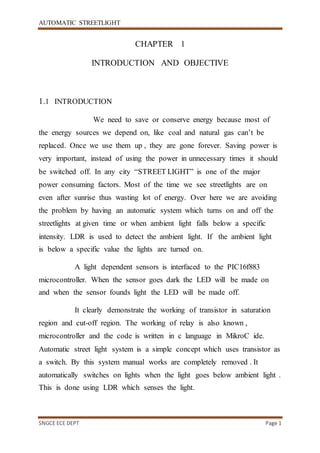
  • 1. AUTOMATIC STREETLIGHT SNGCE ECE DEPT Page 1 CHAPTER 1 INTRODUCTION AND OBJECTIVE 1.1 INTRODUCTION We need to save or conserve energy because most of the energy sources we depend on, like coal and natural gas can’t be replaced. Once we use them up , they are gone forever. Saving power is very important, instead of using the power in unnecessary times it should be switched off. In any city “STREET LIGHT” is one of the major power consuming factors. Most of the time we see streetlights are on even after sunrise thus wasting lot of energy. Over here we are avoiding the problem by having an automatic system which turns on and off the streetlights at given time or when ambient light falls below a specific intensity. LDR is used to detect the ambient light. If the ambient light is below a specific value the lights are turned on. A light dependent sensors is interfaced to the PIC16f883 microcontroller. When the sensor goes dark the LED will be made on and when the sensor founds light the LED will be made off. It clearly demonstrate the working of transistor in saturation region and cut-off region. The working of relay is also known , microcontroller and the code is written in c language in MikroC ide. Automatic street light system is a simple concept which uses transistor as a switch. By this system manual works are completely removed . It automatically switches on lights when the light goes below ambient light . This is done using LDR which senses the light.
  • 2. AUTOMATIC STREETLIGHT SNGCE ECE DEPT Page 2 1.2 OBJECTIVE This project aims to design an automatic streetlight that works in both conventional (electrical ) as well as non-conventional ( solar ) energy resources. Using LDR we control the street light, when the LDR value falls above the threshold value the lights are switched on and when the value falls below the threshold value the lights are switched off . In order to save and conserve energy in an efficient way an intensity controller, based on movement detection is used . This is done using a pair of sensors ( IR transmitter and IR receiver ), whenever the value obtained at the receiver is above the previously set threshold value, an obstacle is identified and the LED connected to the receiver will be switched on .
  • 3. AUTOMATIC STREETLIGHT SNGCE ECE DEPT Page 3 CHAPTER 2 METHODOLOGY AND LITERATURE SURVEY 2.1 METHODOLOGY This paper proposes an effective scheme for controlling the wastage of electricity due to streetlights. It reduces the manual effort by automating the streetlight on the basis of light intensity. The electricity wastage can be reduced by glowing the light on the basis of movement detection. Here three parts have been included under this topic for completed this study. Design architecture is the main block function for the proposed design. While, the hardware specification will detail out the components involved in this design from the sensor components until the controller selection. Software development based on the proposed design will be detail out in software part where the flow of the system operation will be detailed out elaborated. 2.2 LITERATURE SURVEY Hengyu Wu, Minli Tang, propose about The core technology of the street light control system is an AT89S52 single-chip microcomputer. It integrates a power circuit, a fault detect circuit, a photosensitive detection circuit, an infrared detect circuit, an LCD display circuit, a street light control circuit, an a1ann circuit, a pressed key control circuit and so on. This system cans automatically turn on or off the lights and controls the switches according to traffic flow. It expands the fault detect circuit and the corresponding a1arm circuit. It also has a convenient and flexible
  • 4. AUTOMATIC STREETLIGHT SNGCE ECE DEPT Page 4 button control circuit to switch on and off fictions mentioned above. Main weakness is that they didn’t say about the working principle behind the system. It also said to use fault detection circuit which when it is damaged, the voltage is zero, so it will create a problem. This paper is and theoretic proof and shows only simulation result but not as a real time set up experiments. The focus of this paper to build a way for the framework which may leads to many follow up research activities in the Low – rate and also plan to investigate the applicability of this proposal to detect performance. GongSiliang describes a remote streetlight monitoring system based on wireless sensor network. The system can be set to run in automatic mode, which control streetlight according to Sunrise and Sunset Algorithm and light intensity. This control can make a reasonable adjustment according to the latitude, longitude and seasonal variation. Also this system can run in controlled mode. In this mode, we can take the initiative to control street lights through PC monitor terminal. In addition, the system integrates a digital temperature – humidity sensor, not only monitoring the street light real – time but also temperature and humidity. The system is equipped with the high – power relay output and can be widely applied in all places which need timely control such as streets, stations, mining, schools, and electricity sectors and so on. But in this work a wireless network for street light remote control is discussed. In particular, the novelty of the proposal is in the location awareness of nodes, which cannot self - localize themselves. Prototypes have been built using costly hardware. The capability of the ranging measurements, the basis for localization, is not characterized and Showing some problems on the order of one meter. In near future, location aware routing algorithms will developed that will improve the efficiency of the network.
  • 5. AUTOMATIC STREETLIGHT SNGCE ECE DEPT Page 5 Street lighting system Gustavo W. Denardin deals about a control network for a LED street lighting system. The use of LEDs is being considered promising solution to modern street lighting systems, due to their longer life time, higher luminous efficiency and higher CRI. The proposed control network enables disconnection of the street lighting system from the mains during peak load time, reducing its impact in the distributed power system automatically consumption, decrease the management cost and monitor the status information of each street lighting unit. In order to meet the system requirements, a wireless sensor network based on IEEE 802.15.4 TM standard is employed. Its network layer is implemented using geographic routing strategy, which provides slow overhead and high scalability features. However, due to well - known drawbacks of the existing techniques, a novel routing algorithm is proposed. Simulations show that this algorithm leads to a significant improvement of routing performance when applied to sparse large scale scenarios, which is the case of street lighting system. Field tests have been performed on IEEE 802.15.4- compliant wireless control units. The obtained experimental results show that the proposed control network is able to meet the requirements of a LED street lighting system. It mainly deals about safer roadways with intelligent light system to reduce power consumption. This system has automatic street light intensity control based on the vehicular movement and switching ON and OFF of street lights depending on the light ambiance. This will help in reducing the power consumption during hours of meager road usage. The street light module is installed consequently for every certain distance. This paper also aims at reducing road accidents by detecting consumption of alcohol by the driver. This can be implemented using alcohol sensor module which contains skin sensor, breath alcohol sensor
  • 6. AUTOMATIC STREETLIGHT SNGCE ECE DEPT Page 6 and proximity sensor. The skin sensor and breadth alcohol sensor detects the presence of alcohol content and the proximity sensor helps in detecting any kind of malpractice. The novelty of this paper is to effectively reduce the energy consumption of the street lights by controlling the street light’s intensity, sensing both human as well as vehicular movement and injury and death caused by drunk driving can be prevented by prior sensing of the alcohol content in drivers by a simple. Somchai Hiranvarodo describes a comparative analysis of photovoltaic (PV) street lighting system in three different lamps. Namely, a low pressure sodium lamp, a high pressure sodium lamp and a fluorescent lamp have been used for installation in each mast to determine the suitable system to install in a typical rural area of Thailand. All three systems have been mounted with the same module type and wattage in different places within the Rajamangala Institute of Technology, Thanyaburi district, Pathumthani province of Thailand. An operation of solar street lighting system can be divided into 2 period of time, namely, at 18.00-22.00 hours and 05.00-06.00 hours. The design of a control circuit was experimentally done in this work. Protection of the battery from damage for deep discharge and overcharge by a controller was also considered. The life cycle cost analysis (LCCA) is the appropriate method for comparing three different lamps. The present worth of each system can be compared and the least cost option selected. LCCA was based on the key assumptions (year 2002). The results of comparative analysis of the PV street lighting systems with a fluorescent lamp have been the appropriate system for installation in a typical rural area of Thailand when the cost of lamps, system performance and possibility for purchasing the components of the system have been considered. The results of this work can he stated that the average luminance in lux of the fluorescent lamp at design location Pathumthani province of Thailand, has a highest
  • 7. AUTOMATIC STREETLIGHT SNGCE ECE DEPT Page 7 value compared to the low- pressure sodium and high-pressure sodium. On the other hand, the lifetime of the fluorescent lamp has a shortest time compared to other lamps. Nevertheless, the aim of this work is to determine the appropriate system to install in a typical rural area or a typical rural village of Thailand when the cost of lamps and system performance and possibility for purchasing the components of the system are compared. While considering in other areas it is difficult. A.C.Kalaiarasan deal about solar energy based street light with auto- tracking system for maximizing power output from a solar system is desirable to increase the efficiency. In order to maximize the power output from the solar panels, one needs to keep panels aligned with the sun. As such a means of tracking the sun is required. This is a far most cost effective solution than purchasing additional solar panels. It has been estimated that the yield from solar panels can be increased by 30 to 60 percent by utilizing a tracking system instead of a stationary array. This paper describes an automatic tracking system which will keep the solar panels aligned with the sun in order to maximize efficiency. The sun tracking sensor is the sensing device, which sense the position of the sun at the time to time continuously and it gives the sensing output to the amplifier based on light density of the sun. Here the sun tracking sensor is LDR ( light dependent resistor ). The amplifier unit is used to amplify the LDR signals, which makes the low level signal into high level signals and this output is given to the comparator. The LM324 IC is used as an amplifier. Comparator compares the signals and gives the command to the AT89C51 microcontroller. The system presented in this paper will be an efficient method to use the solar energy in remote areas. This system consumes very low power and high efficient lightning. We employ the auto sun tracking system; this can improve the energy stored in battery. This system does not affect the environment because it
  • 8. AUTOMATIC STREETLIGHT SNGCE ECE DEPT Page 8 is pollution free. Our system also consisting of automatic ON, OFF control of the LED lamp, so there is no manual operation and it is not required operators. Radhi Priyasree explains a system to reduce the power consumption of streetlights by avoiding inefficient lighting which wastes significant financial resources each year. This is done by dimming the lights during less traffic hours. For this purpose PIR sensor is used which detects any movement. This work also aims at reducing the fatal crashes and road accidents caused due to alcohol consumption. This is done using skin sensors placed in vehicle doors and also using breadth sensors inside the vehicle. By implementing this death rates due to drunk driving can be reduced to a great extent. The prototype has been implemented and works as expected and will prove to be very useful and will fulfil all the present constraints if implemented on a large scale. It also aims at detecting consumption of alcohol by the driver and if it exceeds certain level it impairs the driver from entering into the vehicle. This prevents occurrence of accidents or any fatal crashes. This initiative will help the government to save this energy and meet the domestic and industrial needs. S.H. Jeong describes about the development of Zigbee based Street Light Control System which control and monitor status of street lights installed alongside load. Lights are switched to ON/OFF by this system’s control command. Its local status information is also monitored by control system via communication channel. Status information which is monitored are on/off status information , energy saving mode status, control group status information and safety related information, etc. To transfer control command and status information between streetlight control system and remote street light control terminals which installed at each light pole, various communication media and communication protocols are using. As
  • 9. AUTOMATIC STREETLIGHT SNGCE ECE DEPT Page 9 communication media, wireless or power lines are used generally. Various frequency bands from tens of MHz to Rebrands are used for wireless case. This Street light control system can save maintenance time and costs and which can improve safety level.
  • 10. AUTOMATIC STREETLIGHT SNGCE ECE DEPT Page 10 CHAPTER 3 PROPOSED SYSTEM Automation, Power consumption and Cost Effectiveness are the important considerations in the present field of electronics and electrical related technologies. Industry of street lighting systems are growing rapidly and going to complex with rapid growth of industry and cities. To control and maintain complex street lighting system more economically, various street light control systems are developed. This proposed system utilizes the renewable technology (Solar) for the sources of light as LED Lamps instead of generally used street lamps such as High Pressure Sodium Lamps, etc. The LED technology is preferred as it offers several advantages over other traditional technologies like energy saving due to high current luminous efficiency, low maintenance cost, high colour rendering index, rapid start up speed, long working life etc. This proposed system makes use of infrared photoelectric sensor (G12-3C3PA) for movement detection.
  • 11. AUTOMATIC STREETLIGHT SNGCE ECE DEPT Page 11 CHAPTER 4 BLOCK DIAGRAM AND EXPLANATION 4.1 BLOCK DIAGRAM 4.2 BLOCK DIAGRAM EXPLANATION In this project the list of hardware components used are given below:  Microcontroller  Transformer  Bridge Rectifier  Voltage Regulator  Light Dependent Resistor  IR Sensors
  • 12. AUTOMATIC STREETLIGHT SNGCE ECE DEPT Page 12  Relay  Diodes  Resistors  Capacitors  Transistor 4.3 HARDWARE DESCRIPTION  Microcontroller ( PIC16f883 ) :- This section provides an introduction to most common word in the embedded system “microcontroller”. It is written to familiarize you with microcontroller terminology and basic microcontroller architecture. A microcontroller is a single chip, self-contained computer which incorporates all the basic components of a personal computer on a much smaller scale. Microcontrollers are often referred to as single chip devices or single chip computers. The main consequence of the microcontroller’s small size is that its resources are far more limited than those of a desktop personal computer. In functional terms, a microcontroller is a programmable single chip which controls a process or system. Microcontrollers are typically used as embedded controllers where they control part of a very larger system such as an appliance, automobile, scientific instrument or a computer peripheral. Microcontrollers are designed to be low cost solutions; therefore using them can drastically reduce part and design costs for a project. Physically, a microcontroller is an integrated circuit with pins along each side. The pins presented by a microcontroller are used for power, ground, oscillator, I/O ports, interrupt request signals, reset and control. In contrast, the pins exposed by a microprocessor are most often memory bus signals (rather than I/O ports).
  • 13. AUTOMATIC STREETLIGHT SNGCE ECE DEPT Page 13 A microcontroller has seven main components: i. Central processing unit (CPU). ii. ROM. iii. RAM. iv. Input and Output. v. Timer. vi. Interrupt circuitry. vii. Buses. Fig. 4.1: The Microcontroller. Microcontrollers do not function in isolation. As their name suggests they are designed to control other devices.
  • 14. AUTOMATIC STREETLIGHT SNGCE ECE DEPT Page 14 Fig:4.2 PIC16F883 IC  PIC16f883 MICROCONTROLLER Microchip manufacture a series of microcontrollers called PIC. (Peripheral interface controller). There are many different flavours available, some basic low memory types, going right up through to ones that have Analogue - To – Digital converters and even PWM built in. A PIC microcontroller is a processor with built in memory and RAM and you can use it to control your projects ( or build projects around it). So it saves you building a circuit that has separate external RAM, ROM and peripheral chips . Microchip is providing the 8-bit, 16-bit and the 32 bit microcontrollers based on the desired application requirement the design engineer can choose from those. Microchip is also providing the software for the microcontrollers where the application programs are written MIKROC IDE, it is also providing the in circuit debugger called MPLAB ICD3. The PIC microcontroller used in this project is pic16f883. These devices feature a 14 bit wide code memory, and an improved 8 level deep call stack. The instruction set differs very little from the
  • 15. AUTOMATIC STREETLIGHT SNGCE ECE DEPT Page 15 baseline devices, but the two additional opcode bit allow 128 registers and 2048 word of code to be directly addressed. There are a few additional miscellaneous instructions, and two additional 8 bit literal instructions, add and subtracts. The mid range core is available in the majority of devices labelled PIC12 and PIC16. The first 32 bytes of the register space are allocated to special purpose registers; the remaining 96 bytes are used for general purpose RAM. If banked RAM is used, the high 16 registers (0x70-0x7F) are global, as are a few of the most important special purpose registers, including STATUS register which holds the RAM bank select bits. The PIC16f883 features 256 bytes of EEPROM data memory, self programming, an ICD, two comparators 11 channels of 10 bit analog to digital converter, 1 capture/compare/PWM and 1 enhanced capture/compare/PWM functions, a synchronous serial port that can be configured as either three wire serial peripheral interface (SPI) or the two wire inter integrated circuit (IC) bus and an enhanced universal asynchronous receiver transmitter (EUSART). All of these features make it ideal for more advanced level A/D applications in automotive, industrial, appliances or consumer applications
  • 16. AUTOMATIC STREETLIGHT SNGCE ECE DEPT Page 16  Features Special Microcontroller Features:  Precision Internal Oscillator:  Factory calibrated to ±1KHz  Software selectable frequency range of 8 MHz to 32 kHz  Software tunable  Two-Speed Start-Up mode  Fail -safe clock monitoring for critical applications  Clock mode switching during operation for low-power operation  Power-Saving Sleep mode  Power-on Reset (POR)  Selectable Brown-out Reset (BOR) voltage  Extended Watchdog Timer (WDT) with its own on-chip RC oscillator for reliable operation  In-Circuit Serial Programming™ (ICSP™) via two pins  In-Circuit Debug (ICD) via two pins  High-endurance Flash/EEPROM cell:
  • 17. AUTOMATIC STREETLIGHT SNGCE ECE DEPT Page 17  100,000 erase/write cycle enhanced Flash program memory, typical  1,000,000 erase/write cycle data EEPROM memory, typical  Data EEPROM retention > 40 years  Self-reprogrammable under software control  Programmable code protection  Peripheral Features:  Device Features:  1 input only pin  25 I/O  High sink/source current 25 mA  Interrupt-on-pin change option  Timers:  TMR0: 8-bit timer/counter with 8-bit pre scaler  TMR1 enhanced: 16-bit timer/counter with pre scaler, External Gate Input mode and dedicated low-power 32 kHz oscillator  TMR2: 8-bit timer/counter with 8-bit period register, prescaler and postscaler  Capture/Compare/PWM (CCP) module  Enhanced Capture/Compare/PWM (ECCP) module with auto-shutdown and PWM steering  Master Synchronous Serial Port (MSSP) module SPI™ mode, I2C™ mode with address mask capability  Enhanced Universal Synchronous Asynchronous Receiver Transmitter (EUSART) module:  Supports RS-485, RS-232 and LIN compatibility  Auto-Baud Detect  Auto-wake-up on Start bit
  • 18. AUTOMATIC STREETLIGHT SNGCE ECE DEPT Page 18  Ultra Low-Power Wake-up (ULPWU) Analog Features:  10-bit 11 channel Analog-to-Digital (A/D) Converter  2 Analog Comparator modules with:  Programmable on-chip Voltage Reference (CVREF) module (% of VDD)  Fixed 0.6 Vref  Comparator inputs and outputs externally accessible  SR Latch mode  Supports RS-485, RS-232 and LIN compatibility  Auto-Baud Detect  Auto-wake-up on Start bit  Ultra Low-Power Wake-up (ULPWU) Transformer :- A transformer is an electrical device that transfers electrical energy between two or more circuits through electromagnetic induction. Electromagnetic induction produces an electromotive force within a conductor which is exposed to time varying magnetic fields. Transformers are used to increase or decrease the alternating voltages in electric power applications. A varying current in the transformer's primary winding creates a varying magnetic flux in the transformer core and a varying field impinging on the transformer's secondary winding. This varying magnetic field at the secondary winding induces a varying electromotive force (EMF) or voltage in the secondary winding due to electromagnetic induction. Making use of Faraday's Law (discovered in 1831) in conjunction
  • 19. AUTOMATIC STREETLIGHT SNGCE ECE DEPT Page 19 with high magnetic permeability core properties, transformers can be designed to efficiently change AC voltages from one voltage level to another within power networks. Figure 4.3 Transformer  Bridge rectifier :- A diode bridge is an arrangement of four (or more) diodes in a bridge circuit configuration that provides the same polarity of output for either polarity of input. Figure 4.4 Bridge rectifier When used in its most common application, for conversion of an alternating current (AC) input into a direct current (DC) output, it is known as a bridge rectifier. A bridge rectifier provides full – wave rectification from a two – wire AC input, resulting in lower cost and weight as compared to a rectifier with a 3-wire input from a transformer with a centre - tapped secondary winding.
  • 20. AUTOMATIC STREETLIGHT SNGCE ECE DEPT Page 20 In the diagrams below, when the input connected to the left corner of the diamond is positive, and the input connected to the right corner is negative, current flows from the upper power supply terminal to the right along the red (positive) path to the output, and returns to the lower supply terminal via the blue (negative) path. When the input connected to the left corner is negative, and the input connected to the right corner is positive, current flows from the lower supply terminal to the right along there (positive) path to the output, and returns to the upper supply terminal via the blue ( negative ) path. In each case, the upper right output remains positive and lower right output negative. Since this is true whether the input is AC or DC, this circuit not only produces a DC output from an AC input, it can also provide what is sometimes called “ reverse polarity protection “. That is, it permits normal functioning of the loads ( wires ) from a DC power source have been reversed, and protects the equipment from potential damage caused by reverse polarity.  Voltage regulator ( 7805 ) : 7805 is a voltage regulator is a member of 78xx series of fixed linear voltage regulator ICs. The voltage source in a circuit may have fluctuations and would not give the fixed voltage output. The voltage regulator IC maintains the output voltage at a constant value. Thexx in 78xx indicates the fixed output voltage it is designed to
  • 21. AUTOMATIC STREETLIGHT SNGCE ECE DEPT Page 21 provide. 7805 provides +5V regulated power supply. Capacitors of suitable values can be connected at input and output pins depending upon the respective voltage levels. A voltage regulator takes an unregulated input voltage and converts it to the exact regulated voltage an electronic circuit requires. Voltage regulators are used in almost every electronic circuit, and the popular 7805 has been used everywhere from computers to satellites, from DVD player and video games to Arduinos and robots. Even though it was introduced in 1972 and more advanced regulators are now available, the 7805 is still in use, especially with hobbyists. The 7805 is a common type of regulator known as a linear regulator. (As its name hints, the 7805 produces 5 volts.) A linear regulator is built around a large transistor that controls the amount of power flowing to the output , acting similar to a variable resistor. A drawback of a linear regulator is that all the "extra" voltage gets converted into heat. If you put 9 Vinto a linear regulator and get 5V out, the extra 4V gets turned into heat in the regulator, so the regulator is only about 56% efficient. Linear regulators such as the 7805 became very popular because they are extremely easy to use: just feed the unregulated voltage into one pin, ground the second pin, and get regulated voltage out the third pin. Another feature that made the 7805 popular is it is almost indestructible - if you short-circuit it, put too much voltage in, or run it too hot, it will shut down before getting damaged, due to internal protection circuits.
  • 22. AUTOMATIC STREETLIGHT SNGCE ECE DEPT Page 22 Figure 4.5 Regulator  Light dependent resistor ( LDR ) :- Light dependent resistors are very useful especially in light or dark sensor circuits. Normally the resistance of an LDR is very high, but when they are illuminated with light, resistance drops dramatically. Electronic onto sensors are the devices that alter their electrical characteristics, in the presence of light. The best known devices of this type are the light dependent resistors, the photodiode and phototransistors. As the name suggest, depending on light the resistance value varies. LDR are made by depositing a film of cadmium sulphide or cadmium selenite on a substrate of ceramic containing no or very free electrons when not illuminated. The longer strip the more the value of resistance. When light falls on the strip the resistance decreases. In the absence of light the resistance can be in the order of 10Kohm to 15Kohm and is called dark resistance. Though LDR is very sensitive to light, the switching time is very high and hence cannot be used for high frequency applications. The below figure shows that when the torch is turned on, the resistance of the LDR falls, allowing current to pass-through it is shown in figure given below.
  • 23. AUTOMATIC STREETLIGHT SNGCE ECE DEPT Page 23 Figure 4.6. LDR Figure 4.7 Symbol of LDR The basic construction and symbol for LDR are shown in above figures respectively. The device consists of a pair of metal film contacts separated by a snake like track of cadmium sulphide film, designed to provide the maximum possible contact area with the two metal films. The structure is housed in a clear plastic or resin case, to provide free access to external light. Practical LDRs are available in variety of sizes and packages styles, the most popular size having a face diameter of roughly 10mm. Practical LDR is shown in below figure. Figure 4.7. Practical LDR  IR Sensors :- An infrared sensor is an electronic device, that emits in order to sense some of aspects of the surroundings. An IR sensor can measure the heat of an object as well as detects the motion. These types of sensors measures only infrared radiations, rather than emitting it that is called as a passive IR sensor. Usually in the infrared spectrum, all the
  • 24. AUTOMATIC STREETLIGHT SNGCE ECE DEPT Page 24 objects radiate some form of thermal radiations. These types of radiation are invisible to our eyes, that can be detected by an IR sensor. The emitter is simply an IR led and the detector is simply an IR photodiode which is sensitive to IR light of the same wavelength as that emitted IR led . When IR light falls on the photodiode, the resistance and the output voltages, change in proportion to the magnitude of the IR light received. An IR sensor circuit is one of the basic and popular sensor module in an electronic device. This sensor is analogous to human visionary senses, which can be used to detect obstacles and it is one of the common applications in real time. Figure 4.8. IR sensor pair  Relay:-Relays are elements connected to the output pins of the microcontroller and are used to turn on/off all that being out off board which has sensitive components: motors, transformers, heaters, bulbs, high voltage components etc. There are various types of relays but all have same operating principles: when a current flows through the coil, it makes or breaks the electrical connections, between one or more pair of contacts. As it is case with optocouplers, there is no galvanic connection ( electrical contact ) between input and output circuits. Relays usually demands both higher voltage and current to
  • 25. AUTOMATIC STREETLIGHT SNGCE ECE DEPT Page 25 start operating but there are also miniature versions which can be activated with a low current directly obtained from a microcontroller port pins. Figure 4.9 Relay  Diodes :- In electronics, a diode is a two-terminal electronic component That conducts primarily in one direction (asymmetric conductance); it has low (ideally zero) resistance to the flow of current in one direction , and high (ideally infinite) resistance in the other. A semiconductor diode, the most common type today, is a crystalline piece of semiconductor material with a p–njunction connected to two electrical terminals. The diode can be viewed as an electronic version of a check valve. This unidirectional behaviour is called rectification, and is used to convert alternating current to direct current, including extraction of modulation from radio signals in radio receivers—these diodes are forms of rectifiers . A semiconductor diode's current–voltage characteristic can be tailored by selecting the semiconductor materials and the doping impurities introduced into the materials during manufacture. These techniques are used to create special – purpose
  • 26. AUTOMATIC STREETLIGHT SNGCE ECE DEPT Page 26 diodes that perform many different functions. In this diode act as a fly back diode (sometimes called a snubber diode, commutating diode, freewheeling diode, suppressor diode, suppression diode, clamp diode or catch diode), it is a diode used to eliminate flyback, which is the sudden voltage spike seen across an inductive load when its supply voltage is suddenly reduced or removed. Figure 4.10. free wheeling diode Figure 4.11 diode  Resistors :- A resistor is a passive two terminal electrical component that implements electrical resistance as a circuit element. In electronic circuit, resistors are used to limit current flow, to adjust signal levels, bias active elements, and terminate transmission line among other uses. High power resistors, that can dissipate many watts of electrical power as heat, may be used as part of motor controls, in power distribution systems, or as test loads for generators. Fixed resistors have resistances that only change slightly with temperature, time or operating voltage. Variable resistors can be used to adjust circuit elements ( such as a volume control or a lamp dimmer ), or as sensing devices for heat, light, humidity, force, or chemical activity.
  • 27. AUTOMATIC STREETLIGHT SNGCE ECE DEPT Page 27 Figure 4.12. Resistors Figure 4.13. Schematic diagram symbols  Capacitors :- A capacitor (originally known as condenser) is a passive two terminal electrical component used to store electrical energy temporarily in an electric field. The forms of practical capacitor vary widely, but all contain at least two electrical conductors(plates) separated by a dielectric(i.e., an insulator that can store energy by becoming polarized). The conductors can be thin film, foils or sintered beads of metal or conductive electrolyte, etc. The non- conducting dielectric acts to increase the capacitors charge capacity. Materials commonly used as dielectrics include glass, ceramic, plastic film, air, vacuum, paper, mica, and oxide layers. Capacitors are widely used as parts of electrical circuit in many common electrical devices. Unlike a resistor, an ideal capacitor does not dissipate energy. Instead a capacitor stores energy in the form of electrostatic field between its place. An ideal capacitor is characterized by a single constant value, its capacitance. Capacitance is defined as the ratio of the electric charge Q on each conductor to the potential difference V between them. The SI unit of capacitance is the farad (F), which is equal to one coulomb per volt (1 C/V). Typical capacitance values range from about 1 pF (10−12 F) to about 1 mF (10−3 F). Capacitors are widely in electronic circuit for blocking direct current while allowing alternating current to pass. In analogue filter networks,
  • 28. AUTOMATIC STREETLIGHT SNGCE ECE DEPT Page 28 they smooth the output of power supplies. In resonant circuit they tune radios to particular frequencies. In electric power transmission system, they stabilise voltage and power flow. Figure 4.14. Capacitors Figure 4.15. Schematic diagram  Transistor (BC547) :- BC547 is an NPN bipolar junction transistors. A transistor, stands for transfer of resistance, is commonly used to amplify current. A small current at its base controls a large current at collector and emitter terminals. BC547 is mainly used for amplification and switching purposes. It has a maximum current gain of 800. It’s equivalent transistor are BC548 and BC549. The transistor terminals requires a fixed DC voltage to operate in the desired region of its characteristic curves. This is known as biasing. For amplification application, the transistor is biased such that it is partly ON for all input conditions. The input signal at base is amplified and taken at the emitter. BC547 is used in common emitter configuration for amplifiers. The voltage divider is the commonly used biasing mode. For switching applications, transistor is biased so that it remains fully ON if there is a signal at its base. In the absence of base signal it gets completely OFF.
  • 29. AUTOMATIC STREETLIGHT SNGCE ECE DEPT Page 29 Figure 4.16 Transistor ( BC547 )
  • 30. AUTOMATIC STREETLIGHT SNGCE ECE DEPT Page 30 CHAPTER 5 CIRCUIT DIAGRAM 5.1 CIRCUIT DIAGRAM 5.2 CIRCUIT EXPLANATION Automatic control of street lights is designed to turn on and turn off street light automatically. This project check the amount of light and street light is turned on and off. Light sensor is used to detect
  • 31. AUTOMATIC STREETLIGHT SNGCE ECE DEPT Page 31 intensity of light. PIC16F883 microcontroller is used to turn on transistor which in turn energize the relay coil and relay turn switches between electricity and solar energy to light the street lights
  • 32. AUTOMATIC STREETLIGHT SNGCE ECE DEPT Page 32 CHAPTER 6 PROGRAMING CODE 6.1 MAIN PROGRAM #include<xc.h> #include"config.h" #include " delay.h" #include"adc.h" #define LDR 0 #define RX1 2 #define RX2 1 #define RELAY PORTBbits.RB0 #define STL1 PORTCbits.RC6 #defineSTL2 PORTCbits.RC7 #define LIGHT_THRESHOLD 300
  • 33. AUTOMATIC STREETLIGHT SNGCE ECE DEPT Page 33 #defineRX2_THRESHOLD 100 #defineRX1_THRESHOLD 100 #defineON 1 #defineOFF 0 void Initilisation(void); voidHardwareSetup(void); void main(void) { UnsignedintRx1Val,Rx2Val,Flag = 0,Flag2 = 0 , Counter = 0; HardwareSetup(); Initilisation(); While(1) { If(read_adc(LDR) > LIGHT_THRESHOLD )
  • 34. AUTOMATIC STREETLIGHT SNGCE ECE DEPT Page 34 RELAY = OFF; else RELAY = ON; Rx1Val = read_adc(RX1); Rx2Val = read_adc(RX2); If(Rx2Val> RX2_THRESHOLD&& Rx1Val> RX1_THRESHOL ) { STL1 = ON; STL2 = ON; Flag = 1; } else if(Rx1Val > RX1_THRESHOLD) { STL1 = ON; STL2 = OFF;
  • 35. AUTOMATIC STREETLIGHT SNGCE ECE DEPT Page 35 } else if(Rx2Val> RX2_THRESHOLD) { STL1 = OFF; STL2 = ON; Flag2 = 1 ; } If(Rx2Val<RX2_THRESHOLD&& Rx1Val <RX1_THRESHOLD && Flag == 1) { STL1 = OFF; STL2 = OFF; Flag = 0; } If(Flag2 == 1)
  • 36. AUTOMATIC STREETLIGHT SNGCE ECE DEPT Page 36 { Counter++; If(Counter == 5000) { STL2 = OFF; Flag2 = 0; Counter = 0; } } // DelayMs(250); } } voidHardwareSetup(void) {
  • 37. AUTOMATIC STREETLIGHT SNGCE ECE DEPT Page 37 /*Set LDR pin as input and analog*/ TRISAbits.TRISA0= 1; ANSELbits.ANS0 = 1; /*Set RX1 pin as in put and analog*/ TRISAbits.TRISA1= 1; ANSELbits.ANS1 = 1; /*Set RX2 pin as input and analog*/ TRISAbits.TRISA2= 1; ANSELbits.ANS2 = 1; /*Set Relay pin as output and digital*/ TRISBbits.TRISB0= 0; ANSELHbits.ANS12 = 0; /*Set street light pins as output and digital*/ TRISCbits.TRISC6= 0; TRISCbits.TRISC7= 0;
  • 38. AUTOMATIC STREETLIGHT SNGCE ECE DEPT Page 38 } voidInitilisation(void) { init_adc(); RELAY = OFF; STL1 = OFF; STL2 = OFF; } 6.2 SUB ROUTINES /* * Delayfunctions forHI-TECH C on the PIC * * Functions available: * DelayUs(x) : Delay specified number of microseconds
  • 39. AUTOMATIC STREETLIGHT SNGCE ECE DEPT Page 39 * DelayMs(x) : Delay specifiednumber of milliseconds * * Note that there are range limits: x must not exceed 255 - for * Crystal frequencies > 12 MHz the range for DelayUs is even * smaller . To use DelayUs it is only necessary to include this file ; * to useDelayMs you must include delay . c in your project . * */ /* Set the crystal frequency in the CPP predefined symbols list in HPDPIC,oron the PICC command line, e.g., picc -DXTAL_FREQ= 4MHZ or picc -DXTAL_FREQ=100KHZ Note that this is the crystal frequency, theCPU clock is Divided by 4. * MAKE SURE this codeis compiled withfull optimization!!!
  • 40. AUTOMATIC STREETLIGHT SNGCE ECE DEPT Page 40 */ #ifndef XTAL_FREQ # define XTAL_FREQ 20MHZ /* Crystal frequency in MHz */ #endif #define MHZ *1000L /* number of kHz in a MHz */ #define KHZ *1 /* number of kHz in a kHz */ #if XTAL_FREQ>= 12MHZ #define DelayUs ( x) { unsigned char _dcnt ; _dcnt= (x)*((XTAL_FREQ)/(12MHZ)); While(--_dcnt != 0) Continue; } #else
  • 41. AUTOMATIC STREETLIGHT SNGCE ECE DEPT Page 41 #define DelayUs(x) { unsigned char _dcnt; _dcnt= (x)/((12MHZ)/(XTAL_FREQ))|1; While(--_dcnt != 0) Continue; } #endif extern voidDelayMs(unsigned char); extern voidDelaySec(unsigned charcnt); /* * Delay functions * See delay.h for details * * Make sure this codeis compiled with full optimization!!!
  • 42. AUTOMATIC STREETLIGHT SNGCE ECE DEPT Page 42 */ #include "delay.h" VoidDelayMs(unsigned charcnt) { # if XTAL_FREQ<= 4MHZ do { DelayUs(996); } while( --cnt); #endif #if XTAL_FREQ> 2MHZ unsignedchar i; do { i =4;
  • 43. AUTOMATIC STREETLIGHT SNGCE ECE DEPT Page 43 do { DelayUs(250); } while(--i); } while(--cnt); #endif } VoidDelaySec ( unsigned charcnt) { Unsigned chari; do { i= 4; do {
  • 44. AUTOMATIC STREETLIGHT SNGCE ECE DEPT Page 44 DelayMs(250); } while(--i); } while(--cnt); } // PIC16F883 Configuration Bit Settings //'C' source lineconfig statements #include<xc.h> //#pragmaconfig statements should precede project file includes. // Use projectenumsinstead of#define for ON and OFF. // CONFIG1 #pragmaconfigFOSC = HS // Oscillator Selection bits (INTOSCIO oscillator: I/O function on
  • 45. AUTOMATIC STREETLIGHT SNGCE ECE DEPT Page 45 RA6/OSC2/CLKOUT pin, I/O function on RA7/OSC1/CLKIN) #pragmaconfigWDTE = OFF //WatchdogTimer Enable bit (WDT disabled and can be enabled by SWDTEN bit of the WDTCONregister) #pragmaconfig PWRTE= OFF // Power-up Timer Enable bit (PWRT disabled) #pragma config MCLRE = ON // RE3/MCLR pin function select bit (RE3/MCLR pin function is MCLR) #pragmaconfigCP = OFF // CodeProtection bit (Program memory codeprotection is disabled) #pragmaconfig CPD = OFF // Data CodeProtection bit (Data memory codeprotection is disabled) #pragmaconfigBOREN = OFF //Brown OutReset Selection bits (BOR disabled) #pragmaconfig IESO = ON
  • 46. AUTOMATIC STREETLIGHT SNGCE ECE DEPT Page 46 //Internal ExternalSwitchover bit (Internal/External Switchover mode Is disabled) #pragmaconfigFCMEN = ON // Fail – Safe Clock Monitor Enabled bit (Fail – Safe Clock Monitor is Disabled) #pragmaconfig LVP = OFF // Low Voltage Programming Enable bit (RB3 pin has digital I/O, HV On MCLR must be used for programming) // CONFIG2 #pragmaconfigBOR4V = BOR40V // Brown-out Reset Selection bit (Brown-out Reset set to 4.0V) #pragmaconfigWRT = OFF // Flash Program MemorySelf WriteEnable bits ( Write protection Off ) Extern unsignedintread_adc ( unsigned char channel); Extern voidinit_adc(void);
  • 47. AUTOMATIC STREETLIGHT SNGCE ECE DEPT Page 47 extern unsignedintGet_adc(unsigned char Channel); #include <pic.h> #include "adc.h" #include"delay.h" void nit_adc() { ADCON0 = 0B00000001; ADCON1 =0B10000000; // TRISA =0XFF; } unsigned intread_adc(unsigned char channel) { Unsignedintadc_value=0;
  • 48. AUTOMATIC STREETLIGHT SNGCE ECE DEPT Page 48 // ADCON0 = ( Channel << 2) + 0xC1; ADCON0bits.CHS =channel ; // enable ADC, // DelayMs(20); GO =1; While(GO); adc_value=ADRESH; adc_value= (adc_value<< 8) | ADRESL; return(adc_value); } unsignedintGet_adc(unsigned char Channel) { ADCON0&= 0xc7; ADCON0 |= (Channel<<3); DelayMs (20);
  • 49. AUTOMATIC STREETLIGHT SNGCE ECE DEPT Page 49 GO_nDONE = 1; While(GO_Ndone); Return((ADRESH<<8)+ADRESL) ; }
  • 50. AUTOMATIC STREETLIGHT SNGCE ECE DEPT Page 50 CHAPTER 7 PCB LAYOUT AND FABRICATION 7.1 PCB FABRICATION Printed Circuit Board ( PCB ) is piece of art. The performance of an electronic circuit depends on the design and layout of the PCB. A PCB mechanically supports and connects components by conductive pathways, etched from copper sheets laminated on to insulated substrate. PCB are used to rotate electrical currents and signals through copper tracts which are firmly bonded to an insulating base. 7.1.1 STEPS FOR PCB FABRICATION PCB fabrication involves the following steps : 1. Drawing the layout of the PCB in the paper. The track layout of the electronic circuit should be made in such manner that the paths are in easy routes. It is then transferred to a Mylar sheet. The sheet is then touched with black ink. 2. The solder side of the Mylar sheet is placed on the shiny side of the five–star sheet and is placed in a frame. Then it is exposed to sunlight with Mylar sheet facing the sunlight. 3. The exposed five–star sheet is put in hydrogen peroxide solution. Then it is put in hot water and shook till unexposed region becomes transparent. 4. This is put in cold water and then the rough side is stuck onto the silk screen. This is then pressed and dried well. 5. The plastic sheet of the five-star sheet is removed leaving the pattern on the screen.
  • 51. AUTOMATIC STREETLIGHT SNGCE ECE DEPT Page 51 6. A copper clad sheet is cut to the size and cleaned. This is placed under screen. 7. As it resistant ink if spread on the screen so that a pattern of tracks and a pad is obtained on a copper clad sheet. It is then dried. 8. The dried sheet is then etched using Ferric Chloride solution ( 32 Baume ) till all the unwanted copper is etched away. Swish the board to keep the each fluid moving. Lift PCB and check all the unwanted copper is removed. Etching is done by immersing the marked copper clad in a ferric chloride solution. After that the etched sheet is dried. 9. The unwanted resist is removed using sodium hydroxide solution. Holes are then dried. 5.1.2 PCB LAYOUT Figure 7.1 : PCB LAYOUT
  • 52. AUTOMATIC STREETLIGHT SNGCE ECE DEPT Page 52 7.2 SOLDERING Soldering is the processes of joining metals by using lower melting point to weld or alloy with the joining surface. SOLDER Solder is the joining material that melts below 427 degree connections between components. The popularly used solders are alloys of tin ( Sn ) and lead ( Pb ) that melts below the melting point if tin. Types : 1. Rosin core :- 60/40 Sn/Pb solders are the most common types used for electronics assembly. These solders are available in various diameters and are most appropriate for small electronics work ( 0.02” – 0.05” diameter is recommended ) 2. Lead free :- Lead free solders are used as more environmental – friendly substitutes for leaded solder, but they are typically not as easy to use mainly because of their higher melting point and poorer wetting properties. 3. Silver :- Silver solders are typically used for low resistance connections but they have higher melting point and are expensive than Sn/Pb solders. 4. Acid - core :- Acid – core solders should not be used for electronic. They are intended for plumbing of non – electronic assembly work. The acid – core flux will cause corrosion of the circuitry and can damage components. 5. Other special solders :- various melting point eutectics : these special solders are typically used for non – electronic assembly of
  • 53. AUTOMATIC STREETLIGHT SNGCE ECE DEPT Page 53 difficult to construct mechanical items that must be assembled in a particular sequence. 6. Paste solders :- these solders are used in the field application or in specialized manufacturing application. FLUX In order to make the surface accept the solder readily, the components terminals should be cleaned chemically or by abrasion using blades or knives. Small amount of lead coating can be done on the portion of the leads using soldering iron, this process is called as fluxers.These are available in petroleum jelly as paste flux. The desirable properties of flux are :-  It should provide a liquid cover over the materials and exclude air gap up to the soldering temperature.  It should dissolve any oxide on the metal surface.  It should be easily replaced from the metal by the molten soldering operation.  Residue should be removed after completing soldering operation.  The most common flux used in hand soldering of electronic components is rosin, combination of mild organic acids extracted from pine tree. SOLDERING IRON It is a tool used to melt the solder and apply it at the joints in the circuit. It operates in 230V supply. The iron at the tip gets heated
  • 54. AUTOMATIC STREETLIGHT SNGCE ECE DEPT Page 54 while few minutes. 50W and 25W soldering irons are commonly used for soldering of electronic circuits. SOLDERING STEPS : 1. Make the layout of the component in the circuit. Plug in the chord of the soldering irons the main to get heated. 2. Straighten and clean the component leads using a blade or knife. 3. Mount the components on the PCB by bending the leads of the components. Use nose pliers. 4. Apply flux on the joints and solder the joints. Solder must be in minimum time to avoid dry soldering and heating up of the components. 5. Wash the residue using water and brush. 6. Solder joints should be inspected when completed to determine if they have been properly made. CHARACTERISTICS OF A GOOD SOLDER JOINTS : A .Shiny surface B . Good, smooth fillet CHARACTERISTICS OF A POOR SOLDER JOINTS : 1. Dull or crystallized surface :- This is an indicator of a cold solder joint. Cold solder joint result from moving the component after
  • 55. AUTOMATIC STREETLIGHT SNGCE ECE DEPT Page 55 soldering has been removed, but before the solder has hardened. Cold solder joints may work at first, but will eventually fail. 2. Air Pocket :- Air pocket ( voids ) result from incomplete wetting of surface, allowing air to be in contact with the connecting metals. This will cause oxidation of the joints & eventual failure. Blow holes can occur due to vaporization of moisture on the surface of the board & existing through the molten solder. Boards should be clean & dry, prior to soldering. Ethanol ( 100% ) can be used as a moisture chaser if boards are wet prior to soldering. 3. Dimples :- Dimples in the surface do not always indicate a serious problem, but they should be avoided since they are precursors to voids. 4. Floaters : Black spots :- Floating in the soldering fillet should be avoided, because they indicate contamination & potential for failure as in the case of voids. These black spots usually results from overheated ( burnt ) Rosin or other contaminants such as burnt wire insulation. Maintaining a clean tip will help to avoid these problems. 5. Balls :- A solder balls instead of a fillet can occur if the trace was heated but the leads were not ( vice versa ). This prevents proper wetting of both surfaces & result in solder being attached to only one surface ( component of trace ). 6. Excess solder :- Excess solder usage can cover up other potential problems & should be avoided. It can lead to solder bridge. In addition, spherical solder joints can result from the application of too much solder.
  • 56. AUTOMATIC STREETLIGHT SNGCE ECE DEPT Page 56 CHAPTER 8 ADVANTAGES AND DISADVANTAGES 8.1 ADVANTAGES  Photo resistors convert light into electricity and are not dependent on any other force.  LDR’s are sensitive, inexpensive, and readily available devices. They have good power and voltage handling capabilities, similar to those of a conventional resistor.  They are small enough to fit into virtually any electronic device and are used all around the world as a basic component in many embedded systems.  LDR may be connected either way round and no special precautions are required when soldering. 8.2 DISADVANTAGES  Can be more complicated to align detector pairs ( IR transmitter and IR receiver ).  Prescribed system is sensitive to ambient light and require careful shielding.  Photo resistors are only sensitive to light and no other force can power it without risking damage. Also,they are unable to detect low light levels and may take a few seconds to deliver a charge while their electrons build up momentum.
  • 57. AUTOMATIC STREETLIGHT SNGCE ECE DEPT Page 57 CHAPTER 9 CONCLUSION AND FUTURE SCOPE 9.1 CONCLUSION The aim of this project was to design and implement an automatic street light using PIC16f883 microcontroller, which can be used to avoid manual operation for switching street light on and off. In order to save and conserve energy in an efficient manner, street lights are on only when a movement is detected by a movement detection sensors.This proposed system is in par with government’s policy of energy conservation by reducing consumption of electricity and efficient use of energy, so it can be termed as an innovative project in street lightning that can be implemented in the roads like state and national highways. 9.2 FUTURE SCOPE This project has scope for improvement and many enhancements can be done to make it more reliable and interesting. For example, when a vehicle or a person meet with an accident street light remains on , a system can be introduced to inform the respective authorities. Similarly, a system can be introduced to inform the technicians about the default. All this will be possible, however, only through innovation, hard work and above all proper use of technology.
  • 58. AUTOMATIC STREETLIGHT SNGCE ECE DEPT Page 58 CHAPTER 10 REFERENCES  8051 MICROCONTROLLER AND EMBEDDED SYSTEMS BY MAZZIDI  Magazines  Electronics for you  WWW.google.com  http://www.electronics-tutorials.ws  http://www.electronics.indianetzone.com  http://www.wikipedia.org  http://www.encyclobeamia.solarbotics.net  IOSR Journal of Electronics and Communication Engineering (IOSR- JECE)  www.electronicsmanufacturers.com  www.engineersforyou.com  International Journal of Innovative Research in Science, Engineering and Technology (An ISO 3297: 2007 Certified Organization) Vol. 3, Issue 2, February 2014