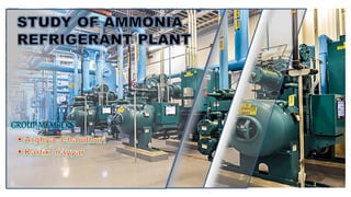
Ammonia refrigeration plant
•Download as PPTX, PDF•
5 likes•3,042 views

Ammonia refrigeration plant installed in NDRI,KARNAL. designed by Arghya & Kartik. this explains the specifications of refrigeration units like Compressor, Condenser, Expansion Valves and Evaporators.their specification and working. Even advantages of ammonia has been explained.

Recommended
More Related Content
What's hot
What's hot (20)
Similar to Ammonia refrigeration plant
Similar to Ammonia refrigeration plant (20)
Recently uploaded
Recently uploaded (20)
Ammonia refrigeration plant
- 2. Introduction- The basic purpose of a refrigeration plant is to produce cooling effect. Refrigeration systems use basic physics to move heat energy out of one area into another, leaving the first area cooler than it was before. The refrigerator in your kitchen does the same work, it prevents your milk from going bad. Massive Industrial facilities like dairy processing plants and food processing plants rely on large-scale refrigeration systems for their day-to-day operations.
- 3. Insulated pipe Compressed vapour Water coming from tank Liquid refrigerant Uninsulated pipe Indications 1) Compressor 5)Receiver 2)LPHP Cut-Off 6)Condenser 3) Temperature control 7)Evaporator 4) Expantion valve Water going to tank Fig-1.2 “Layout of Ammonia Refrigerant plant” 1 4 5 7 3 2 6
- 4. Type of refrigerant used:- Refrigerant used in this plant is Ammonia (NH3) and it is a natural refrigerant. It is a colourless gas with a characteristic pungent smell and it is also known as R-717. It has been used in industrial applications since the 1930s and is generally acknowledged as being the most efficient refrigerant. It has a low boiling point and is favoured because it is a highly energy efficient refrigerant which also has minimal environmental impact, having zero ODP (Ozone Depletion Potential) and zero GWP (Global Warming Potential). It is lighter than air and NH3 boils at −33.34 °C (−28.012 °F) at a pressure of one atmosphere.
- 5. COMPRESSO R CONDENSO R EXP. VALVE EVAPORATO R COMPRESSION EXPANSION CONDENSATIO N EVAPORATION PROCESSES INVOLVED IN REFRIGERATION CYCLE
- 6. COMPRESSO R CONDENSO R EXP. VALVE EVAPORATO R COMPRESSION PROCESSES INVOLVED IN REFRIGERATION CYCLE CONDENSATION EXPANSION EVAPORATION
- 7. COMPRESSO R CONDENSO R EXP. VALVE EVAPORATO R COMPRESSION PROCESSES INVOLVED IN REFRIGERATION CYCLE CONDENSATIO N EXPANSION EVAPORATION
- 8. COMPRESSO R CONDENSO R EXP. VALVE EVAPORATO R COMPRESSION PROCESSES INVOLVED IN REFRIGERATION CYCLE CONDENSATIO N EXPANSION EVAPORATION
- 9. COMPRESSO R CONDENSO R EXP. VALVE EVAPORATO R COMPRESSION PROCESSES INVOLVED IN REFRIGERATION CYCLE CONDENSATIO N EXPANSION EVAPORATION
- 10. COMPRESSO R CONDENSO R EXP. VALVE EVAPORATO R COMPRESSION PROCESSES INVOLVED IN REFRIGERATION CYCLE CONDENSATIO N EXPANSION EVAPORATION
- 11. COMPRESSOR A A compressor is a mechanical device used to raise pressure [Fig-1.3] There are 4 compressors in this refrigerant plant – 2 of them are used for Ice Bank tank and 2 of them are used for Cold water tank. All of them are reciprocating type compressor. Flywheel of compressor is connected with motor with the help of 4 V-belts. Motor used is of 50 hp and is started with the help of Star Delta starter. Motor transfers power to flywheel with the help of belts and then flywheel rotates the crank shaft and then connecting rod transfer rotatory motion from crank shaft into reciprocating motion to piston. Motor specifications in Table -1.2. B of Motor 37 LCW200L 68 8PDP 1450 301 2800705-10 63A3 Table-1.2 C is 12 TR and one of The low-pressure m evaporator drawn valve. The refrigerant e and then delivered lve. The temp of ng compression g at very high RPM to friction, which de compressor. ket inside compressor being flow to keep the lubricating oil below ween piston and body. essor which g oil so that no th it. For more r to Table-1.1 and of D 4 3
- 12. CONDENSER Main function of condenser is to condense the vaporize ammonia refrigerant that is coming from the compressor discharge valve by loss of heat to the surrounding. Condenser has no. of tubes through which ammonia refrigerant is flowing as in Fig-1.4. Due to multiple tube surface area is increased followed by increase in heat transfer rate. There is water circulating system by which there is raining of water of the condenser tubes to condense the refrigerant. There is a sink of water below this condenser, water that is raining over tubes of condenser fall in sink by taking away refrigerant latent heat converting the refrigerant into liquid, duration of falling down the water get cold by flowing air and from the sink this water gets circulated continuously with help of centrifugal pump. We generally use water having potassium permanganate (KMnO4) in it to prevent growth of fungus, bacteria etc [Only if we use stored water for a while]. If we are using fresh water we need not to mix potassium permanganate in water. Fig- 1.4 Condenser
- 13. • Used for holding extra amount of ammonia refrigerant. • Used where evaporator volume is large compared to condenser volume. • Placed between condenser and filter . • Filled partly with vapour and partly with liquid ammonia during working. • A plastic pipe of normal water having number holes installed over it. All specifications in Table-1.3 Specifications of pressure vessel (ammonia receiver) Thickness of walls 6 mm Max. permissible working pressure 150 Psi Design pressure 275 Psi Length 5.689 m Installation date 2002 Table – 1.3 Cold water line Ammonia outlet pipe Ammonia inlet pipe Water Water circulating pipe Ammonia Receiver
- 14. EXPANSION VALVE Produce cooling effect by throttling mechanism. Control flow of refrigerant by use of filler bulb filled with similar gas as in system. The valve open against spring pressure in the valve body . As load increase filler bulb sense increase in temperature and gas will expand cause the expansion valve to open. Installed near evaporator. Require special design considerations due to the erosive effects of ammonia vapours. Fig-1.6 Expansion Valve
- 15. EVAPORATOR Main cooling part of ammonia refrigeration system. A. Ammonia enter in evaporator coil in liquid form after expansion from expansion valve. B. Ammonia refrigerant is flowing through evaporator coil which take latent heat from products kept inside and convert into vapours. C. Evaporator coil made up of copper mainly. D. Ammonia refrigerant is in vapour form upon leaving evaporator coil.
- 16. OIL SEPARATOR Oil separator function is to separate the oil from ammonia refrigerant gas. Oil separator is mounted in the high-pressure pipe between the compressor and condenser. Oil that is used in compressor for lubricating purpose in piston or in other parts, small amount of oil is mixed with refrigerant gas and come out from discharge valve during discharging. To separate this oil use of oil separator is necessary. Fig-1.8 Oil Separator
- 17. FILTER DRIER 1. Filter-drier in a refrigeration or air conditioning system has two essential functions: a) To adsorb system contaminants, such as water, which can create acids b) To provide physical filtration. The ability to remove water from a refrigeration system is the most important function of a drier. Water can come from many sources such as leakage in pipes, trapped air, to name a few. 2. The three most common type of desiccants used are molecular sieve, activated alumina and silica gel.
- 18. LOG BOOK OF AMMONIA REFRIGERANT PLANT AT EXPERIMENTAL DAIRY- There is a log book which has to be maintained by operators working in ammonia refrigerant plant. They have to fill in the desired information in log book which is used to keep record of the information. [As in Table-1.4] From seeing log book one can see that there are many columns having relevant information like temperature of water, suction pressure of refrigerant, discharge pressure of refrigerant, which pumps are working etc. There is also a column of comment in which the operator can write something if there is something unusual in working of refrigeration plant like if there is shut down of plant due to leakage, shut down of plant due to maintenance etc.
- 19. Table-1.4 Log table of ammonia refrigerant plant
- 21. Dairy processing handbook By Tetrapak Refrigeration and air conditioning By C.P. Arora Refrigeration and air conditioning By Eurasia Publishing house www.wikipedia.org Class Lectures REFERENCE