
Recommended
Recommended
More Related Content
What's hot
What's hot (20)
Similar to Operation and maintenance of Divider Block Systems
Similar to Operation and maintenance of Divider Block Systems (20)
Operation and maintenance of Divider Block Systems
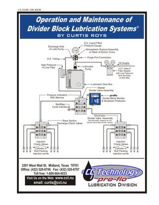
- 1. Operation and Maintenance of Divider Block Lubrication Systems BY CURTIS ROYS c Atmospheric Rupture Assembly on Back of Anchor Cross S.S. Tubing S.S. Liquid Filled Pressure Gauge Purge Port Connection Lubricator Gear Box Pressure Indicators With Memory Lubricator Pump Master Divider Valve Assembly proflo Divider Block Monitor & Shutdown Protection Oil Supply NeoMag Cycle Indicator Discharge Side of Lube Pump High Pressure In-Line Filter Injection Check Valves Cylinder or Rod Packing Injection points Secondary Divider Valve Assembly (All lubrication systems do not require secondary divider valves) Base Section Discharge Check Valves U.S. $19.99 / CAN. $29.99 Set Mode T C C "PROTECTING COMPRESSORS WORLD WIDE" Midland, Texas 1-800-664-4033 C. C. Technology Inc. prO flOCLASS I, DIV II Groups A,B,C,D NRTL/C IrDA PORT AVG 20 RR M o d e l - P F 1 US Copyright Registered 2001 T C C Injection Check Valves Cylinder or Rod Packing Injection points 3201 West Wall St. Midland, Texas 79701 Office: (432) 520-6700 Fax: (432) 520-6707 Toll free: 1-800-664-4033 Visit Us on the Web: www.cct.nu email: curtis@cct.nu CCT- Delta-P Filter Adapter with Low Pressure Non By-Pass In-line filter 25 50 75 100 125 150 IIII II I II II I I I I I I I I II I I I I II I II 25 50 75 100 125 150 IIII II I II II I I I I I I I I II I I I I II I II B-118
- 2. This manual is dedicated to all the people, compressor operators and companies I have had the pleasure of doing business with during the past 25 years.Aspecial thanks to Dan Toth and Ariel Corporation for allowing me to train the people attending the training school each month in their facility in Mount Vernon, Ohio. Thanks to David McCoy and all the field service personnel atAriel Corporation for their confidence and support in my goal to educate the compressor industry for troubleshooting and operation of the divider blocklubricationsystem. There are many trials and tribulations while designing, installing and troubleshooting divider block lubrication systems on slow speed and high speed compressors. Without the learning process and the mistakes made and corrected during my learning stages, this manual would not have been possible. All of the sections of this training manual are concepts formed from several years of experience and practical field application. If the principles in this manual are utilized in operation and maintenance of the divider block system,theoperatorshouldexperienceyearsoftroublefreedependableservice. From the end user to the design engineer of divider block systems, you are always welcome to call C C Technology for brainstorming, troubleshooting or design applications. I appreciate the opportunity to provide assistance in the design, installation troubleshootingand/oroperationofdividerblocklubricationsystems. Copyright (C) 2004 by C CTechnology Inc. All rights reserved. Printed in the United States of America. No part of this publication may be reproduced in any part without written permission from the author. For information on lubrication products or to obtain copies of this publication contact C C Technology 3201 West Wall St. Midland Texas,79701orcall(432)520-6700,fax(432)520-6707. “ACKNOWLEDGEMENT” C. C. Technology Inc. T C CC C TechnologyC C Technology All trademark names in this manual are the property of theirrespective companies and not associated with C CTechnology Inc. Roys
- 3. Recommended Upgrades, Preventive Maintenance and Additions to Benefit Divider Block Systems...............................................................................page 2,3 Lubrication System Design: Lubrication System Design Sheets.............................................................................. page 41,42,43,44,45,46 Lubrication Rates: CalculatingBaseLubricationRates: CompressorCylinders&RodPacking...........................................................................page18 LubeOilRecommendationsforVariousGasStreamComponents...................................page 19 Operational Procedures: Optimizing Divider Block Lubrication Systems .............................................................page 4,5 Locating Blockage In Divider Block Lubrication Systems .............................................page 6,7,8,9 Pressure Testing Divider Blocks...................................................................................page 10 TestingforLeakingCheckvalves...................................................................................page13 BalancingHighPressureLubeSystems.........................................................................page15,16,17 LubricatorPumps.........................................................................................................page5 PressureGauges..........................................................................................................page5 PurgingAirFromDividerBlockLubricationSystems......................................................page14 CheckValveInstallation................................................................................................page13 DividerBlockIdentificationTwin&Single.......................................................................page10,23 Divider Block Cross Porting.........................................................................................page 24,25,26,27,28 Troubleshooting the Divider Block Lubrication System..............................................page 38,39,40 Lubrication System Components & Accessories: Filtration......................................................................................................................page5 CheckValves...............................................................................................................page12 Reset Pressure Indicators w/Memory...........................................................................page 11 Atmospheric Rupture Assembly ..................................................................................page 11 Lubrication System Purge Gun.....................................................................................page 14 SB & Trabon Divider Block Assembly Instructions........................................................page 20 Lincoln Divider Block Assembly Instructions................................................................page 21 Dropsa Divider Block Assembly Instructions................................................................page 22 No-Flow Switches and Cycle Indicators: DNFT & PROFLO Jr. Comparison ...............................................................................page 29 PROFLOJr.InstallationProcedure................................................................................page30 PROFLO Jr. Troubleshooting........................................................................................page 31 PROFLOJr. Wiring&TestingforCorrectOperation........................................................page32 NeoMagCycleIndicator-OperationandInstallation.........................................................page33 Kenco.........................................................................................................................page40-9-A Lincoln........................................................................................................................page40-9-B Trabon/Lubriquip.........................................................................................................page40-9-C Proflo Divider Block Monitor & Shutdown Protection: Proflo Button Operation................................................................................................page 34 ProfloInstallationProcedure.........................................................................................page35 Proflo Wiring Instructions............................................................................................page 34 Fluid Flow Trending Software Download & Viewing Procedure.....................................page 36-37 CCTechnologyProducts...........................................................................InsideBackCoverPage TABLE OF CONTENTS T C C QUICK DIRECTORY 3201 West Wall St. Midland, TX 79701 (432) 520-6700 Nation Wide 1-800-664-4033 Fax: (432) 432-520-6707 C. C. Technology Inc. Visit Us On the Internet www.cct.nu 1
- 4. 3201 West Wall St. Midland, Texas 79701 Office: (432) 520-6700 Fax: (432) 520-6707 Toll free: 1-800-664-4033 Visit Us on the Web: www.cct.nu email: curtis@cct.nu RECOMMENDED UP-GRADES, PREVENTIVE MAINTENANCE AND ADDITIONS TO BENEFIT OPERATION OF ALL DIVIDER BLOCK LUBRICATION SYSTEMS 1.InstallNonBy-PassFiltersonSuctionSideofLubricatorPumps Several situations have existed where trashin the lubricator pump created a low flow condition.The low flow condition is extremely hazardous to the compressor and can possibly cause phantom shutdowns or the cylinders, packing, rods or rings to fail prematurely. Filtration prior to the lubricator pump is essential.A25 to 100 micron filter on the inlet side of the pump is extremely beneficial.This filter should be a non by-pass design, easy to remove, clean and/or replace. The non by-pass filter will give field service technicians and operators a quick fix for trash problems on the inlet side of the pump.(See page 5 Filtration) Note: Do Not use a typical automotive type filter. A typical automotive filter will by-pass when the filter becomes clogged introducing trash into the lubricator pumps, divider blocks and check valves.Always check with the filter manufacturer to ensure the filters installed on the compressor are non by-pass which will alleviate the problem of trash into the system. 2. Install Discharge Manifolds and/ora Pressure Gauge on the Discharge Side of the LubricatorPump A discharge manifold assembly consists of an anchor cross, purge port, pressure gauge and atmospheric rupture disc, all of which should be incorporated into all well designed divider block lubrication systems. The pressure gauge is a critical instrument to monitor divider block operation and lubrication system pressure. Fluid movement of the pressure gauge indicates proper operation of the divider block system. Erratic movement or sudden drops in pressure indicate by-passing or sticking pistons in the divider blocks or the presence of air or gas in the system.The pressure gauge gives the field service technicians or operator an inexpensive tool to recognize problems with by-passing pumps or divider blocks before major damage to the cylinders and packing occur. Note: Never assumethelubricatorpumpordividerblockswillnotby-passbecauseitisnew.(Seepage5PressureGauges) 3.InstallaPurgePortontheDischargeSideofLubricatorPump An addition of the CCT pump discharge manifold (PCA) will allow a purge gun to be easily connected to the lubrication system and eliminate air from entering the system . The manifold is designed to provide field service technicians or operators easy access to purge the divider block system of air before startup or after any maintenance on the lubrication system. A check valve must be in place at the purge point to ensure air free oil is in the system when the purge gun is removed.This eliminates phantom shutdowns and air locking problems. (See page 14 Purging AirFromDividerBlockSystems) 4.InstallResetPressureIndicatorsonDividerBlocks An essential tool to allow field service technicians or operators to easily and immediately locate excessive system pressure or blockage in individual divider blocks, tubing runs or injection points. (See Page 11 Pressure Ind.) 5. Install an Oil Head Fitting (OHF) and Extreme Duty Check (XDC)Valve The OHF ensures a minimum of 1 inch of oil head in front of the check valve.The oil head keeps a liquid seal on the check valve and increases reliability for many years. It is never recommended to install check valves in a verticalorhorizontalpositionwhichwouldnotallowforaliquidseal.(Seepage13) 6.InstallBasePlateCheckValves Base plate check valves should always be installed on each working outlet of the divider block base plate to stabilize the operation of the divider block and eliminate gas or air from entering the divider block due to faulty or failed injection check valves. This will minimize phantom shutdowns until the faulty injection check valves can be replaced.(Seepage12CheckValves) 3201 West Wall St. Midland, TX 79701 (432) 520-6700 1-800-664-4033 fax: (432) 520-6707 2
- 5. 3 7. Double Poppet S.S. CheckValves Install the CCT ( XDC) Extreme duty double poppet 10,000 PSI check valve at all injection points.The poppet o-ring seal is extremely effective for positive sealing. Install the Oil Head Fitting where high pressures or temperatures exist and in the presence of gases known to create problems with elastomer seals. Failed check valve problems have been alleviated with the installation of the Oil Head Fitting (OHF) and Extreme Duty Check (XDC). (See page 12 CheckValves) 8. Review DividerBlock System Design forMaximum Efficiency and Recommended Oil Consumption To insure adequate oil supply to high pressure cylinders and packing, the divider block system should be designed to eliminate over lubricating lower pressure suction and interstage cylinders and packing. The total system does not need extra lubrication when only one or two cylinders and packing are operating with high discharge pressures. The high pressure injection points should reflect the needed amount of oil without over lubricating the medium to low pressure points. This will increase the efficiency of the compressor, reduce operating costs and eliminate problems associated with excessive lubrication. Contact the compressor manufacturer or a professional divider block system designer. Fill in one of the Design Sheets on pages 41 thru 43 or on the CCTwebsite (www.cct.nu) specific to your compressor and email or fax it to C C Technology. This will enable the design engineer to check your systemforcorrectdividerblocks. 9.TestDividerBlocksforPressureIntegrity All divider blocks are metal to metal sealing surfaces and the possibility of by-passing is always present. By- passing could be a result of excessive clearance between the piston and bore of a new divider block or from millions of cycles each year creating wear between the piston and bore. Note: Never assume tolerances between the piston and bore are acceptable even if the divider block is new and the piston is cycling properly. Test all divider blocks for integrity at least every two years with the CCT Single Point Test Device (SPTD). When injection pressures are over 1000 PSI, the divider blocks should be tested for integrity or replaced every 24 months. Divider blocks are much less expensive to replace than compressor cylinders, rods or packing, not to mention the cost of labor and lostrevenuefromdowntime. (SeePressureTestingDividerBlockspage10) 10.InstallBalancingValvesonDividerBlockSystemswithHighdifferentialPressure Use of balancing valves are recommended to assist divider blocks to accurately proportion lubricant when differential injection pressures of approximately 1200 PSI to 1500 PSI are present in a divider block system. Balancing valves should be installed on all low pressure injection points when 1200 PSI to 1500 PSI differential pressure exists in the system.This will eliminate divider block by-pass problems and create a fluid movement of the divider block system eliminating excessive wear to the divider block piston. Differential pressure is the actual difference between the pressure needed to inject oil into each cylinder or packing lubrication points. The divider block system will not typically see final discharge pressure of the compressor. Pressure gauges must be installed in the lubrication line with each balancing valve to enable field service technicians or operators to monitor and balance the system correctly. (See Balancing High Pressure Divider Block Systems pages 15,16,17) 11. LubricatorGearbox Overflow into CompressorFrame Several lubricator pumps have been discovered by-passing oil into the lubricator box. If tubing is connected from the lubricator box to the compressor frame to move excessive oil out of the lubricator tank it is impossible to detect a by-passing lube pump. Remove the tubing designed for overflow of the lubricator tank and plug the tank and frame tubing fitting. If the pump is by-passing it will be very noticeable by overfilling the lubricator box. If the operator prefers to keep the by-pass tubing in place it should be removed from the compressor frame every 6 to 12 months and left open to the atmosphere for several hours. If the lube pump is by-passing excessive oil will drip excessive oil from the tubing. This indicates to operators or service technicians the lubricator pump is faulty. Pressure test lubricator pumps every 12 months to ensure the pump will build sufficient pressure to blow the atmospheric rupture disc in the system. If the sight glass on the lube box is covered or stained with dirty oil, you will never know if the oil level is correct. Clean the sight glass and lube box every year and inspect the cam lobes in the box for wear. Never assume the lubricator pump will not by-pass because it is new or has been refurbished. 12. LubricatorCamshaft and PumpWear It is absolutely necessary for the operator to remove all lube pumps, completely drain the oil from the lube box andcheckforwearonthepumprockerarms,camlobesandinternalgearsofthelubricatorreservoirevery12months. (Recommended Upgrades & Maintenance Continued) Visit Us On the Internet: www. cct.nu 3201 West Wall St. Midland, TX 79701 (432) 520-6700 1-800-664-4033 fax: (432) 520-6707
- 6. A Divider Block Lubrication System is designed to receive oil from a positive displacement pump and divide the oil in precise amounts to be injected into each point to be lubricated (packing gland, cylinder, etc.). The divider block system is capable of lubricating as many points as needed by addition of divider block sections to the system but must be engineered for each individual application to insure that the correct amount of lubricant is dispensed to each lubrication point. Divider block systems that are designed with a combination of the compressor manufacturers recommended lube rates and the field experience of the designer will eliminate problems due to insufficient lubrication or excessive oil consumption. The divider block system consists of filtration, a lubricator pump, divider block metering sections, pressure indicators, check valves and flow monitoring shutdown devices. The Divider Block Lubrication System is termed a single line progressive system because it contains only one oil supply line from the pump discharge to the master divider block and from the master divider block to the secondary blocks. A master divider block is the first divider block downstream from the lube pump. A secondary divider block is any divider block receiving oil from the master divider block. If one piston in the system stops moving, a blockage has occurred and the remaining pistons stop moving. This results in a complete loss of oil flow to the cylinders and packing. The blockage creates a higher than normal system pressure as the lube pump continues to inject oil into the stalled system trying to move the pistons and overcome the blockage. The excessive pressure is signaled by a pressure gauge installed on the discharge side of the pump. The exact point of blockage is indicated by pressure indicator pins (See page 9 Figure “D”) mounted on the front of the divider block. The system continues to build pressure until it is relieved to the atmosphere by means of an atmospheric rupture assembly (page 11). Notice:All divider block systems must have an atmospheric rupture Installed on the discharge side of the pump. The Divider Block Lubrication System Cannot Tolerate: (1) Foreign Material of Any Kind (2) Air or Gas Anywhere in the System (3 ) Leaks ofAny Kind. Optimizing Divider Block Lubrication Systems INTRODUCTION DESCRIPTION & OPERATION Lubrication System Components Atmospheric Rupture Assembly on Back of Anchor Cross Atmospheric Rupture Assembly Injection Check Valve Base Section Discharge Check Valve Tubing Pressure Gauge Purge Port Connection Lubricator Gear Box Reset Pressure Indicator With Memory Lubricator Pump Master Divider Valve Assembly Oil Flow Indicator Port Plug Piston Enclosure Plugs Discharge Side of Lube Pump Injection Check Valves Cylinder or Packing Gland Injection Points Injection Check Valves Cylinder or Packing Gland Injection Points Reset Pressure Indicator With Memory Mechanical No-flow Shutdown Divider Block with NeoMag Cycle Indicator Divider Block Section Divider Block with Cycle Indicator Pin proflo Jr. No-Flow Shutdown LUBE SENTRY 527-100-130 LUBRIQUIP - HOUDAILLE TRABON AND MANZEL MODEL # ELECTRIC SWITCH 200 00 051 25 0 0 0 0 01 30 0 0 0 0 5 T C C 4 Secondary Divider Valve Assembly (All lubrication systems do not require secondary divider valves) Base Section Check Valves Visit Us On the Internet: www. cct.nu “Proflo” Divider Block Monitor & Shutdown Protection Set Mode T C C "PROTECTING COMPRESSORS WORLD WIDE" Midland, Texas 1-800-664-4033 C. C. Technology Inc. prO flOCLASS I, DIV II Groups A,B,C,D NRTL/C IrDA PORT AVG 20 RR M o d e l - P F 1 US Copyright Registered 2001 High Pressure In-Line filter CCT- Delta-P Filter Adapter with Low Pressure Non By-Pass In-line filter CLASS I, DIV. I Groups A,B,C,D NRTL/C M o d e l - J r 1 US Copyright Registered 2004 proflo Jr. "PROTECTING COMPRESSORS WORLD WIDE" Midland, Texas 1-800-664-4033 C y c l e I n d i c a t o r R A T E D 3 0 0 V D C 1 2 0 V A C @ . 5 a m p s P R O T O Y P E 1S E R I A L # 2 - M I N U T E SA L A R M RED - N.O. ORANGE - N.C. YELLOW - SWITCH CLOSURE OUT GREEN - GND. NeoMag Cycle Indicator 25 50 75 100 125 150 IIII II I II II I I I I I I I I II I I I I II I II 25 50 75 100 125 150 IIII II I II II I I I I I I I I II I I I I II I II B-118
- 7. LINCOLN OPTIMIZING AND DIVIDER BLOCK LUBRICATION SYSTEMS Oil Supply: The basic lubricator uses a box suction pump which pulls oil from the reservoir. This system depends on oil supplied to the lubricator reservoir through an oil level controller by gravity feed from an overhead oil supply or by a pressurized oil supply from the engine or compressor crankcase. The lubrication system using box suction pumps is a perfect environment for sludge and water to form. This is normally attributed to old or inadequate gaskets, high temperatures and leakage through the lubricator pump hand priming assembly. Inspect and clean the lubricator reservoir annually. When possible it is recommended to utilize a single pump and pressurized oil supply for all lubrication systems. Filtration: Dirt or foreign material of any form cannot be tolerated and will cause serious damage or blockage to all lubrication system components. If contamination does not cause immediate malfunction or damage, it will greatly reduce the expected life of all components of the divider block system. Installation of a spin on type non-by-pass filter before entering the lube system is essential for protection of the lubricator pump. Utilizing a 10 to 25 micron high pressure in-line filter downstream of the lubricator pump will provide years of trouble free service from all divider blocks. For optimum reliability and performance change or clean all filter elements every three (6) to six (12) months depending on the application of the divider block system and the environment. Lubricator Pumps: The lubricator pump of choice is the pressurized inlet pump. These pumps eliminate priming problems and contamination problems associated with box suction lubricators by receiving filtered, pressurized oil directly to the suction inlet of the pump. The pistons in all lubricator pumps are metal to metal wearing surfaces precision fitted to extremely close tolerances. With use, lubricator pumps start to wear, piston clearance becomes excessive and without warning the pump will leak oil past the piston into the lubricator gear box. If the lube pump becomes difficult to adjust for lube rates or system cycle time becomes erratic, check for lubricator pump bypass. By-passing pumps can also be recognized by the lubricator reservoir continuously overfilling with oil. If tubing from the lubricator reservoir is plumbed into the compressor crankcase to eliminate overflow, a by-passing pump cannot be detected unless removed from the reservoir and tested with shop controlled testing procedures. Note: All lubricator pumps should be pressure tested annually for reliability to demonstrate the ability to build sufficient pressure to inject oil through the divider block system, into the injection points and rupture the atmospheric disc.. Pressure Gauges, Purge Port & RuptureAssembly: Pressure Gauge: The pressure gauge is essential for monitoring the lube system operation. Any problems with the lube system will immediately be indicated by the pressure gauge. The pressure gauge should swing with a fluid movement with no erratic pressure changes. If the pressure gauge builds excessive pressure and drops immediately to an extremely low pressure, check for system blockage, (page 6,7,8,9), air in system (page 14), by-passing divider blocks, (page 10) or leaking check valves (page13). The pressure gauge should indicate adequate pressure needed to inject oil into the final discharge cylinder. If the gauge does not indicate ample pressure, the lube pump cannot be adjusted for consistent lube rates or cycle time, immediately test the lube pump for by-passing. Purge Port: The purge port is necessary for purging the system before start-up or after maintenance on the lube system. Atmospheric Rupture Assembly: The atmospheric rupture assembly is the only exit for the oil if the system should encounter blockage or excessively high pressure. Divider Blocks: All divider block pistons are metal to metal surfaces, precision fitted to extremely close tolerances. In low to medium pressure service divider blocks should be pressure tested every 12 to 24 months. This test will confirm the piston tolerances are close enough to build adequate pressure to force oil into the injection point without by- passing. Note: To insure proper operation, all new divider blocks should be pressure tested before installation. (See Pressure Testing Divider Blocks page 10). Check Valves: Check valves are an essential part of every lubrication system. Leaking check valves enable air or gas to enter the lubrication system and can be associated with phantom shutdowns and/or blown atmospheric rupture discs. Double ball metal seat or double poppet soft seat check valves are both excellent check valves depending on the application. Discharge check valves installed on the base plate of the divider block will alleviate air or gas from entering the divider block should an injection check valve fail. (See Check Valve Information (page 12) and Check Valve Installation andTesting page 13) proflo Monitor Pages 34,35,36 , and Mechanical No-Flows : For troubleshooting proflo see page 32. See page 39,8-C, & 40,9-A,B,C for troubleshooting mechanical no-flows. 5 S.S. Double Poppet Soft Seat Check 7500PSI C.S. Double Ball Metal Seat Check 8000PSI S.S. Base Plate Discharge Check 7500PSI PART# 0-750014 7500 PSI ULTRA-CHECK PART# 0-80018 8000 PSI CC TECH 750018R HIGH PRESSURE In-Line Fiter S.S. Washable Element HIGH PRESSURE In-Line Fiter Bronze Element LOW PRESSURE Delta-P Non By-Pass Filter PREMIER CCT-HVLP CCT / Alemite / SB / Trabon DropsA proflo Jr. Lincoln Kenco CCT / Lincoln TRABON Purge Port for Prelube Before Startup Pressure Cross Assembly Installed on Lubricator Pumps Atmospheric Rupture Assembly Trabon/Lubriquip Alemite & SB
- 8. Locating Blockage in Divider Block Lubrication Systems DIVIDER BLOCK IDENTIFICATION DIVIDER BLOCK ASSEMBLY DESCRIPTION CONTAMINATION BLOCKAGE SEPARATION BLOCKAGE AIR Figure A. Components of The Divider Block Assembly (see pages 20,21,22) The divider block assembly consists of an inlet and end section, intermediate sections plus a minimum of three divider blocks. The divider block baseplate assembly is held together with tie rods and nuts. (Figure A). Each divider block contains a piston of predetermined size to inject a calculated amount of oil into each point receiving lubrication. A Master Divider Block is the first divider block downstream from the lube pump. A Secondary Divider Block is any divider block receiving oil from the master divider block. (Figure E, page 9). BLOCKAGE IN THE SYSTEM If blockage occurs in the divider blocks, lube lines, check valves or injection points the system will build excessive pressure attempting to overcome the blockage. Excessive pressure is limited and signaled by the use of pressure indicators and atmospheric rupture assemblies. (See page 11). When blockage occurs and oil flow discontinues, monitoring devices protect the compressor by alarm or compressor shutdown. O-Rings O-Rings Intermediate Base Inlet Section Lube Outlets End Section Indicator Port PlugPiston Enclosure Plug Tie Rod Tie Rod Nuts Stamping located on the front of the divider block indicates the quantity of oil discharged by that particular block with each cycle of the piston. The oil discharged with each cycle of the piston is expressed in thousandths of cubic inches (12 = .012 in , 9 = .009 in , etc.). Divider blocks are manufactured to require one (1) or two (2) outlets unless cross port bars are designed into the system. The number of lube outlets required is indicated by a stamped letter (S= single, one outlet only, T= twin, two outlets required). See Figure B. Never block any outlet that is designed to discharge lubricant. Notice: Divider block pistons are individually fitted to each bore to extremely close tolerances and cannot be turned end for end or interchanged with other pistons. Dirt or foreign material of any form cannot be tolerated and will cause serious damage or blockage to the lubrication system components. If contamination does not cause immediate malfunction, it will greatly reduce the expected life of the divider block system components. Cleaning the divider block and components will only temporarily solve the problem. The source of contamination must be eliminated. Proper filtration of oil to at least 25 microns before entering the lube system is essential for trouble free dependable lubrication system operation. All filter elements must be changed on a periodic basis. Hard wax or soap like deposits in the divider block system indicate separation of the lubricant thickener out of solution or the presence of animal fat lubricants. Cleaning the divider block system will only temporarily solve this problem. Consult you lubricant supplier for alternate lubricants. When changing to a new lubricating oil always inquire if they are compatible to avoid problems with the lubricator pumps, divider blocks and check valves. Air cannot be tolerated in lines or components.Although not usually the cause of damage to the lube system, air in the lube lines and components is often the cause of system locking, lubrication failure or phantom compressor shutdown. All divider block system components must be full of oil and free of air for proper operation. (See page 14). 3 3 Divider Block Figure B. Intermediate Base & Divider Block O-Rings Piston Piston Size & Outlets Required Indicator Port Plug Indicator Port Piston Enclosure Plug Piston Enclosure Plug Enclosure Plug O-Ring Seal 6 Visit Us On the Internet: www. cct.nu 3201 West Wall St. Midland, TX 79701 (432) 520-6700 1-800-664-4033 fax: (432) 520-6707
- 9. LOCATING BLOCKAGE IN DIVIDER BLOCK LUBRICATION SYSTEMS Blockage in divider block systems is caused by: (1) Crushed Tubing Line (2) Blocked Injection Point Make a visual inspection of the system and check for crushed tubing lines. Check to ensure all divider blocks required to discharge oil do not have pipe plugs installed in the base plate outlet. Divider blocks with a letter “T’ stamped on the front should have (2) two outlets open from the base plate. Divider blocks with a letter “S” stamped on the front should have (1) one outlet open on the base plate and one outlet plugged. (See page 23 Defining Divider Blocks) ALL SERVICING MUST BE DONE UNDER THE CLEANEST POSSIBLE CONDITIONS Dirt, foreign material and air are the worst enemies of all lubrication systems. Always use clean filtered oil (A): Divider Block Systems with One Divider Valve Assembly and Reset Pressure Indicator Pins: Step A1: Connect a manual lubrication system purge gun to the inlet of the divider block assembly or purge port on the pressure cross assembly as shown on page 8 Figure "C" and slowly operate pump. Continue to raise pressure until an indicator pin pops out. See page 8 Figure "D". If no indicator pin pops out, blockage is in the divider block assembly. See Step 4 page 8. If an indicator pin pops out, the extended pin indicates blockage down the discharge line common to that pin. Remove the tubing connection from the check valve at the injection point common to the divider block with the indicator pin extended out. Slowly operate the purge pump. If high pressure exists check tubing and fittings. If the purge pump operates freely and oil flows from the tubing, connect the purge pump to the check valve at the injection point. Slowly operate the purge pump. If high pressure exists the check valve or the injection point on the cylinder or packing gland is plugged. Correct as necessary. Always test the check valve for reverse leakage by pumping oil into the outlet side. If oil leaks through the check valve replace it immediately. (B): Divider Block Systems with One Divider Valve Assembly without Reset Pressure Indicator Pins: Step B1: With manual purge gun connected to the divider block or purge port on the pressure cross assembly as in StepA1, remove each indicator port plug one at a time and slowly operate the pump. Do not exceed 1,000 PSI. If pressure on the gauge holds replace the indicator port plug. Remove and replace each indicator port plug one at a time until pressure drops on the pressure gauge and the divider block cycles freely when operating the purge pump. If the pressure gauge drops after removing an indicator port plug and the divider valve cycles freely the blockage is downstream of that individual divider block. Replace the indicator port plug and remove the tubing connection from the check valve at the injection point. Slowly operate the purge pump. If high pressure exists check tubing and fittings. If the purge pump operates freely and oil flows from the tubing connect the purge pump to the check valve at the injection point. Slowly operate the purge pump. If high pressure exists the check valve or the injection point on the cylinder or packing gland is plugged. Correct as necessary. Always test the check valve for reverse leakage by pumping oil into the outlet side of the check valve. If oil leaks through the check valve replace it immediately. If all indicator port plugs are removed and the divider block will not cycle, blockage is in the divider block assembly. See Step 4 page 8. (C):Divider Block Systems with Master and Secondary Divider Blocks with Pressure Indicator Pins installed: Step C1: Connect a manual lubrication system purge gun as shown on page 9 Figure "E" to the inlet of the master divider block assembly or purge port on the pressure cross assembly and slowly operate pump. Continue to raise pressure until an indicator pin pops out. See page 8 Figure "D". The pin indicates blockage down the discharge line common to that pin. If an indicator pin pops out, see Step 2. If no indicator pin pops out, blockage is in the master divider block assembly. See Step 4 page 8. (D): Divider Blocks Without Pressure Indicator Pins: Step D1: With manual purge gun connected to the master divider block or purge port on the pressure cross assembly remove each indicator port plug one at a time and operate the pump. Do not exceed 1,000 PSI. If pressure on the gauge drops and the divider block cycles freely after an indicator plug is removed, the blockage is downstream of that individual divider block. See Step 2. If all indicator port plugs are removed and the master divider block will not cycle, blockage is in this divider block assembly. See Step 4 page 8. Step 2: Testing indicates blockage is located downstream of the Master divider block. If installed remove the indicator pin, or indicator port plug and connect the purge gun to the indicator port on the front of the master divider block that feeds the blocked line. See page 9 Figure "F". Remove all indicator port plugs in the secondary divider block assembly. If oil can be easily pumped through all indicator ports, the blockage is not in the tubing line or the divider valve. See Step 3. If oil does not flow freely through the indicator ports the blockage is in the secondary divider block or its supply line. Disconnect the tubing line from the inlet of the secondary divider block assembly and pump the purge gun to verify blockage is not in the tubing line. If blockage is in the divider block assembly, see Step 4 page 8. Step 3: Remove indicator port plugs or indicator pins from the secondary divider blocks. Connect purge gun to each indicator port of the secondary divider blocks one at a time and slowly operate pump. See page 9 figure "G". If high pressure exists in any port tested blockage has been located. Check tube, fittings, check valves, packing gland and cylinder injection points by pumping oil into each. 7 3201 West Wall St. Midland, TX 79701 (432) 520-6700 1-800-664-4033 fax: (432) 520-6707
- 10. LOCATING BLOCKAGE IN DIVIDER BLOCK LUBRICATION SYSTEMS (cont'd.)8 Step 4: When testing indicates blockage is in the divider block, before disassembly, remove all piston enclosure plugs. See page 6 Figure A. Without removing the pistons use a brass rod and finger pressure only to move each piston back and forth. If all pistons are moveable, replace the enclosure plugs and retest the assembly by pumping oil into the inlet. (Blockage may have been dislodged and the assembly may be in working condition without further service.) If piston is jammed or wax like substance or dirt is found in the piston bore, the divider block must be disassembled and cleaned. Before removing, make a note of divider block positions on the base from top to bottom. See Figure C. (Example 9T-12T-24T). Working with one block at a time, remove the piston with a brass rod. If the piston is stuck, try removing it in the opposite direction. The piston may have to be forced out by lightly tapping it with a brass rod only. Do not use any type of hard metal object to remove the piston. After removal, thoroughly wash the piston and divider block with a clean suitable solvent. Blow out all ports in the divider block and use a small piece of wire to clean out all passages. Inspect divider block bore and piston for scratches or score marks. If either of these are damaged a new divider block must be installed. The final step is to thoroughly clean the base sections and blow out all ports with compressed air. Caution: DO NOT use emery cloth, bearing cloth or any type of abrasive substance to clean or smooth any piston or bore. To do so will cause the divider block to bypass and can cause extensive damage to compressor components. Pistons are precision fitted to each bore to extremely close tolerances and cannot be turned end for end or interchanged with other pistons. After entire divider block assembly has been cleaned, inspected and all blocks and pistons appear in good condition, lubricate and reassemble, positioning the divider blocks on the base in their original order as per notes. Make sure all pistons slide smoothly and fit snugly in divider block bores. After assembly, test for proper operation and purge the system with a purge gun using oil common to the system. To insure proper operation of the divider block system, it is absolutely necessary that all tubing and components be filled with clean oil common to the system. All air must be purged from tubing and components before start-up. (See page 14 Purging Divider Block Systems) S.S. Tubing Purge Port Connection Purge Here before Start-up Divider Block Assembly Discharge Side of Lube Pump 200 00 051 25 0 0 0 0 01 30 0 0 0 0 5 T C C 0 500 1000 501 0 00 25 3000 2000 Check Valves 24T 9 T 12T Reset Pressure Indicator Pins or Port Plugs Divider Block Inlet Purge here Figure "D". Figure "C". Lubrication System with One Divider Block Assembly INDICATOR PIN OUT Divider Block Side View Manual Purge Gun 3201 West Wall St. Midland, TX 79701 (432) 520-6700 1-800-664-4033 fax: (432) 520-6707
- 11. LOCATING BLOCKAGE IN DIVIDER BLOCK LUBRICATION SYSTEMS (cont'd) 9 Master Divider Block Inlet 24S 12S 12T 24T 12T 12T12T 24T 12S Manual Purge Gun Check Valves Cross Port Bar Indicator Port Plug Pressure Indicator Pin 0 500 1000 0 15 0 25 00 003 0 02 00 Secondary Divider Block Inlet Secondary Divider Blocks Figure "D". INDICATOR PIN OUT Divider Block Side View Figure "E" Lubrication System with Master and Secondary Divider Blocks Figure "F" Locating Blockage Down Stream of Master Divider Block Figure "G" Locating Blockage Down Stream of Secondary Divider Block Manual Purge Gun Manual Purge Gun Secondary Divider Block Secondary Indicator Port Plug or Indicator pin Secondary Indicator Port Plug Removed Indicator Port Master Divider Block Indicator Port Secondary Divider Block 24S 12S 12S 0 050 1000 1500 250003 00 0 20 0 12T 12T 24T Check valves 12T 12T 24T Check valves Secondary Divider Block Secondary Indicator Port Plug or Indicator pin 24S 12S 12S 12T 24T 12T 12T 24T Check valves 0 500 1000 1500 250003 00 0 20 0 3201 West Wall St. Midland, TX 79701 (432) 520-6700 1-800-664-4033 fax: (432) 520-6707 NeoMag Cycle Indicator
- 12. Pressure Testing Divider Blocks For By-Passing DESCRIPTION All divider blocks are metal to metal sealing surfaces and the possibility of oil passing around the piston to a point of least resistence is always present. By-passing can be a result of excessive clearance between the piston and bore of a new divider block or from millions of cycles each year causing wear between the piston and bore. For this reason it is necessary to test each individual divider block before installation and/or after continued use. This will confirm the piston to bore tolerances are close enough to build adequate pressure to force oil into the injection point. Note: Never assume tolerances between the piston and bore are acceptable even if the divider block is new and the piston is cycling properly. Pressure test all divider blocks in low to medium service at least every two years. When high injection pressures are present or there is no filtration of the oil before the lubrication system the divider blocks should be pressure tested or replaced every 12 months. Divider blocks are much less expensive to replace than compressor cylinders, rods or packing, not to mention the cost of labor and lost revenue from down time. Procedure for Testing Divider Blocks For By-Passing To test divider blocks for by-passing, a manual purge gun equipped with a pressure gauge and capable of developing 5000 PSI is necessary. For pressure testing the divider block use a 10-weight oil at room temperature to simulate hot oil. Test each divider block assembly complete with pin indicators installed.Test only one divider block at a time.. A. Place the divider block assembly in an open container with all base outlets open. Connect the purge gun to the inlet of the divider block assembly. Operate the purge gun to cycle the divider block several times to purge air from the assembly and verify that oil will flow freely from all outlets. Divider blocks should cycle at less than 300 PSI. (See “A”) Divider blocks stamped with a “T” should have only one outlet on the base plugged during testing of that side of the piston. Each outlet of the divider block stamped with a “T” must be plugged and tested one side at a time (See “B”). Individual testing of each outlet ensures both sides of the piston will build adequate pressure.All divider blocks stamped with an “S” on the front should have both outlets on the base plugged to test for by-passing (See Figure “C”) This will test both sides of the piston at the same time. (See page 23 Defining Divider Block Identification) B. Plug the outlet on the base under the divider block being tested with a 1/8” pipe plug. If a tubing fitting is installed in the base, plug the fitting with a tubing plug. Leave all other outlets open. Operate the purge gun until the pressure gauge indicates 3000 PSI. The block may cycle once or twice, but should pressure to 3500 PSI immediately. Stop pumping oil into the divider valve at 3500 PSI. Check the plug in the discharge outlet to confirm there are no external leaks. The pressure gauge should not lose more than 1000 PSI during a 30-second test. Note: Testing the divider blocks at higher pressures is necessary if the application dictates higher system operation. If the pressure gauge on the purge gun drops suddenly and oil squirts from the other outlets, a by-pass condition exists. The piston is worn and is allowing oil to by-pass. This is not acceptable and the divider block must be replaced. If the tested block does not lose more than 1000 PSI in 30 seconds, relieve the pressure, move the plug to the next outlet and repeat the same test. After all divider blocks have been pressure tested with this recommended procedure, the divider blocks should be reassembled, purged with oil and put back in service. Divider Block Inlet 24T 24T 24T 12S 12S 12S 12T 12T 12T Manual Purge Gun Divider Block With “S” Base Outlets Open Oil Flowing Freely Plugged to Test One Side of the “T” Twin Block All Other Outlets Open Both Sides Plugged to Test “S” Single Block All Other Outlets Open 0 50 0 1000 5 0 1 0 25000 30 0 20 00 0 50 0 1000 15 00 2005 000 3 2000 0 50 0 1000 15 00 2005 003 0 2000 “A" Divider Block All Outlets Open “B” Testing “T” Divider Block “C” Testing “S” Divider Block 10 Visit Us On the Internet: www. cct.nu 3201 West Wall St. Midland, TX 79701 (432) 520-6700 1-800-664-4033 fax: (432) 520-6707