
Recommended
More Related Content
What's hot
What's hot (20)
Similar to Basic applications of CBCT
Similar to Basic applications of CBCT (20)
More from DrMohamedEkram
More from DrMohamedEkram (9)
Recently uploaded
Recently uploaded (20)
Basic applications of CBCT
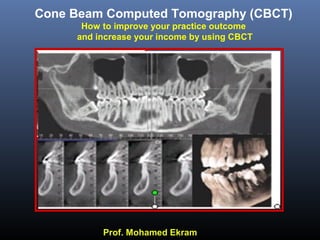
- 1. Prof. Mohamed Ekram Cone Beam Computed Tomography (CBCT) How to improve your practice outcome and increase your income by using CBCT
- 2. M.Ekram Cone Beam Computed Tomography (CBCT) is the new frontier in dental radiology. It is probably the fastest growing area in our discipline. The advanced technology in computer science made it necessary to make use of it in dental radiography.
- 3. Objectives of this presentationObjectives of this presentation Introduce Cone Beam principles Discuss applications of CBCT Demonstrate some interesting & unexpected lesions. Answer your questions M.Ekram
- 4. Why take a 3D image? 2D 3D When viewingWhen viewing two - dimensionaltwo - dimensional images , theimages , the three - dimensionalthree - dimensional anatomy responsible foranatomy responsible for the image must be considered.the image must be considered.
- 6. 2 D representation of the implant area3D reconstruction of the implant area
- 10. M.Ekram Principles of Computed Tomography in General SCANORA 3D
- 11. A Axial 3D 3DimentionalSagittal C Coronal Sagittal Coronal Axial Planes of the head (cuts)
- 12. Production of a single axial cut. Each rotation produces another slice roduction of Conventional CT Image The default is a slice M.Ekram Fan shaped Beam
- 14. Generation of views in Conventional Medical CT 3 - D Coronal Saggittal 3. Reconstruction 1. Slice is the Default M.Ekram
- 15. How the CBCT Images (CBCT) are Generated ? detector Cone-shaped x-ray beam X-ray source M.Ekram
- 16. 1. 3 – D Default 3. Reconsruction Axial Coronal Sagittal M.Ekram Generation of views in CBCT SCANORA 3D
- 17. Complete data can be reformatted to produce images in other planes Generation of CBCT Images Axial Sagittal Coronal M.Ekram
- 18. 2-D images can, then, be obtained in any plane, including the M.Ekram Reformatted panoramic cross-sectional cuts of the jaws.
- 19. X-ray source object Line detector Movement of translation and axis of rotation From Multislice CT... M.Ekram Fan shape beam X-ray source object axis of rotation Flat panel detector ...to real 3D CBCT Cone or Rectangle What is the difference between conventional CT and CBCT ?
- 20. M.Ekram Advantages of CBCT over Conventional CT What is the difference between conventional CT and CBVT ?
- 21. Smaller in size & less space ccupyingSmaller in size & less space ccupying M.Ekram
- 22. Time saving.Time saving. The decrease scanning time 20 – 40 seconds minimizes the risk of motion artifacts.
- 23. Safer withSafer with SignificantSignificant exposure doseexposure dose reductionreduction Exposure dose is 78 % to 96 % less than conventional CT A s L ow A s R easonably A chievable M.Ekram
- 24. Conventional medical CT Cone Beam CT
- 25. This is not exactly applicable to the first generations of CBCT units.
- 26. The CBCT machine should possess different Fields of View (FOV).
- 27. When the large FOV is the only available FOV the following results: Less safety and more radiation exposure for the patient. false bone density results due to huge amount of scattered radiation. When the Small FOV is the only available FOV the following results: Limited coverage of the cranio-facial region with few amount of information.
- 28. Dentally more specific than Conventional CTDentally more specific than Conventional CT M.Ekram Advantages of CBCT over Conventional (medical) CT
- 29. Supplied with more specific softwareSupplied with more specific software M.Ekram
- 30. Easier orientation of theEasier orientation of the occlusal planeocclusal plane M.Ekram This is essential for correct slice direction Face bow + Chair movement
- 31. Bone window Soft tissue modes Soft tissue and hard tissue filters. M.Ekram
- 32. Color coding of structures of different CT numbers. M.Ekram
- 33. Applications of CBCT Implant site evaluation. Assessment of impacted teeth. 3D & 2D Orthodontic/ orthognathic evaluation. Maxillofacial trauma & fractures. Maxillofacial lesions. TMJ assessment. Maxillofacial deformities & alveolar Clefts. Examination of the Paranasal sinuses Air way examination. Other dental applications as endodontics & Peridontal assessment. M.Ekram
- 35. Bone quantity With 1 :1 Correspondence (in all 3 dimensions, vertical, B-L & M-D) Bone quality (only gives an idea) Bone anatomy Location of the vital structures Presence of any minute bone pathology or small remaining root fragments which cannot be always detected by 2D plain radiographs Useful information obtained from the CBCT for the dental implantologist: M.Ekram
- 36. Mesio-distal dimension: to determine the number & diameter of the implants to be placed 1.5- 2mm between an implant & a natural tooth & 3mm between 2 implants Bone Quantity Vertical dimension: to determine the implant length taking into consideration 2mm safety margin from the IAC & 1 mm from the maxillary sinus & nasal floor.ucco-lingual dimension: to determine the implant diameter mm of bone should be present all around the implant M.Ekram
- 37. Only gives an idea about estimated bone t Bone quality is determined by obtaining the CT. number (Bone density) in HU from the CBCT software. Mainly Cortical Symphysis Mainly Spongy Post Mandible Thick Cortical & Dense Spongy Post Mandible Thin Cortical & Less Dense Spongy Ant Maxilla M.Ekram D5
- 38. D1 1250 or more D2 850 -1250 D3 350 - 850 D4 150 - 350 D5 < 150 Quality in Hounsfield Units (in CT) D5
- 39. Location of the Inferior alveolar canal from the crest of the alveolus leaving a 2mm safety margin Mental foramen. Inferior border of the mandible. Maxillary sinus. Nasal floor. Location of the vital structures Nasal floor Cross section In the IAC M.Ekram
- 40. Radiographic tracing is achieved by delineating the inferior alveolar canal on he radiograph for easier measurement recording. Radiographic Tracing : M.Ekram
- 41. Radiographic Tracing ( Cross sections ) M.Ekram
- 42. Bone measurements (Height & B-L width) M.Ekram
- 43. Bone Undercuts M.Ekram Lingual perforation & injury to the adjacent vessels due to improper drilling direction.
- 45. Compuer guided implant surgery and Surgical Guides M.Ekram Precise preoperative planning software can be used to accurately plan the placement of dental implants using integrated data from a CBCT scan.
- 46. Disadvantages of Implant site analysis Programs based on medical CT Systems. Very high patient radiation dose. No notable updating (e.g.DentaScan 2+). More expensive than CBCT. Time consuming. No limited area examination is always possible. Most of the cross sectional cuts in a single examination are non-corrected (cannot be customized).
- 49. 3D printing derived from CBCT Data
- 51. Impacted Teeth. M.Ekram Visualization of the impacted teeth in the 3 dimensions. The relation of the impacted tooth to the vital structures The effect of the impacted tooth on adjacent teeth.
- 52. Interpretation of 3D images M.Ekram Surface mode & transparent modes 3D Endoscopy
- 53. Reported Case
- 55. CBCT In Periodontal evaluation
- 56. M.Ekram Facial and lingual aspects
- 57. 3D Lingual panoramic view 3D facial panoramic view
- 60. Multiple 2D images can be reformatted 3 D image (surface mode)Multiple 2D images can be reformatted M.Ekram Orthodontics & Orthognathic surgery
- 66. Exact extent of the lesion in 3 dimensional prospective Relation of the lesion to vital structures. invasion to adjacent structures or not. CBCT In Maxillofacial lesions
- 67. Reported case
- 71. M.Ekram Examination of Sailvary Glands
- 72. Reported case
- 73. Salivary Stone In The Duct
- 74. Segmentation Submandibular S.G duct Stone
- 75. M.Ekram 3D reconstructed imageSagittal View Duct Stone Examination of Sailvary Glands
- 76. M.Ekram Sagittal View Axial view Cross section view Sailvary Glands Duct Stone
- 78. M.Ekram 3D reconstructed imageSagittal View Duct Stone Examination of Sailvary Glands
- 79. Reported Case
- 80. Deep lobeSuperficial lobe Coronal section of the skull Showing pooling of the contrast material in the superficial and deep lobes of the parotid gland. RT
- 81. 3-D view of skull Showing pooling of the contrast solution in the superficial lobe of the parotid gland. Pooling of contrast material RT Sialographic appearance compatible with Sjogren’s Syndrome.
- 83. It assess the 3D extension and dimension of the defects to evaluate the amount & Orientation of the graft material M.Ekram
- 84. M.Ekram Extent of the defect in The sagittal plane
- 86. Inferior & medial displacement of the fractured segment Maxillofacial Trauma. M.Ekram Mandibular body fracture
- 87. Gun shot injury
- 88. Reported case
- 89. A 14 years old boy with history of a gunshot. Clinically presented with an anterior open bite with facial lacerations. CBCT examination revealed bilateral comminuted complex fracture.
- 90. 3D visualization
- 91. Treatment was performed by simple MMF
- 93. CBCT of the TMJ CoronalSagittal Axial 3D 3Dimentional
- 94. M.Ekram
- 95. Endodontics Atypical anatomy Internal resorption
- 97. Airway measurements & color coding Measurements color coding M.Ekram
- 100. Server and PACS survices Radiology Center Access with all images loaded. Referring doctor Access to the server site (Address). Referring doctor Access to his own sector ImageTransfer.
- 101. Serial Unexpected finding No of Cases 1 Caries 2 Periodontal disease 3 Dental anomalies 4 iInfections 5 Odontogenic & allied lesions 6 Forein bodies 7 Total No of cases The Unexpected Findings
- 102. Reported Case
- 103. Aim of examination: Implant planning upper R #4 & #5
- 104. Unexpected finding: Periapical radiolucency related to Upper left #7 The roots are in very close proximity to the maxillary sinus
- 105. Reported Case
- 106. Aim of examination: Implant planning upper anterior region (missing teeth and others indicated for extraction).
- 108. Unexpected finding: Carious lesion in the lower right t# 4 & Lower left # 3
- 110. ? ? ? ?
- 112. Now you can restart your practice on these new basis safely, quickly, and with greater diagnostic information and knowing all the details about your patient.
- 113. Thank You for Your attention