1. Fredrick Kendrick Electronic Engineering Dept. ET1220
AND-NAND-OR-NOR-GATES
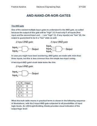
The AND gate
One of the easiest multiple-input gates to understand is the AND gate, so-called
because the output of this gate will be "high" (1) if and only if all inputs (first
input and the second input and . . .) are "high" (1). If any input(s) are "low" (0), the
output is guaranteed to be in a "low" state as well.
In case you might have been wondering, AND gates are made with more than
three inputs, but this is less common than the simple two-input variety.
A two-input AND gate's truth table looks like this:
What this truth table means in practical terms is shown in the following sequence
of illustrations, with the 2-input AND gate subjected to all possibilities of input
logic levels. An LED (Light-Emitting Diode) provides visual indication of the
output logic level:
3. Fredrick Kendrick Electronic Engineering Dept. ET1220
It is only with all inputs raised to "high" logic levels that the AND gate's output
goes "high," thus energizing the LED for only one out of the four input
combination states.
The NAND gate
A variation on the idea of the AND gate is called the NAND gate. The word
"NAND" is a verbal contraction of the words NOT and AND. Essentially, a NAND
gate behaves the same as an AND gate with a NOT (inverter) gate connected to
the output terminal. To symbolize this output signal inversion, the NAND gate
symbol has a bubble on the output line. The truth table for a NAND gate is as one
might expect, exactly opposite as that of an AND gate:
4. Fredrick Kendrick Electronic Engineering Dept. ET1220
As with AND gates, NAND gates are made with more than two inputs. In such
cases, the same general principle applies: the output will be "low" (0) if and only
if all inputs are "high" (1). If any input is "low" (0), the output will go "high" (1).
The OR gate
Our next gate to investigate is the OR gate, so-called because the output of this
gate will be "high" (1) if any of the inputs (first input or the second input or . . .)
are "high" (1). The output of an OR gate goes "low" (0) if and only if all inputs are
"low" (0).
A two-input OR gate's truth table looks like this:
5. Fredrick Kendrick Electronic Engineering Dept. ET1220
The following sequence of illustrations demonstrates the OR gate's function, with
the 2-inputs experiencing all possible logic levels. An LED (Light-Emitting Diode)
provides visual indication of the gate's output logic level:
7. Fredrick Kendrick Electronic Engineering Dept. ET1220
A condition of any input being raised to a "high" logic level makes the OR gate's
output go "high," thus energizing the LED for three out of the four input
combination states.
The NOR gate
As you might have suspected, the NOR gate is an OR gate with its output
inverted, just like a NAND gate is an AND gate with an inverted output.
NOR gates, like all the other multiple-input gates seen thus far, can be
manufactured with more than two inputs. Still, the same logical principle applies:
the output goes "low" (0) if any of the inputs are made "high" (1). The output is
"high" (1) only when all inputs are "low" (0).
The Negative-AND gate
A Negative-AND gate functions the same as an AND gate with all its inputs
inverted (connected through NOT gates). In keeping with standard gate symbol
convention, these inverted inputs are signified by bubbles. Contrary to most
peoples' first instinct, the logical behavior of a Negative-AND gate is not the same
as a NAND gate. Its truth table, actually, is identical to a NOR gate:
8. Fredrick Kendrick Electronic Engineering Dept. ET1220
The Negative-OR gate
Following the same pattern, a Negative-OR gate functions the same as an OR
gate with all its inputs inverted. In keeping with standard gate symbol convention,
these inverted inputs are signified by bubbles. The behavior and truth table of a
Negative-OR gate is the same as for a NAND gate:
9. Fredrick Kendrick Electronic Engineering Dept. ET1220
The Exclusive-OR gate
The last six gate types are all fairly direct variations on three basic functions:
AND, OR, and NOT. The Exclusive-OR gate, however, is something quite different.
Exclusive-OR gates output a "high" (1) logic level if the inputs are
at different logic levels, either 0 and 1 or 1 and 0. Conversely, they output a "low"
(0) logic level if the inputs are at the same logic levels. The Exclusive-OR
(sometimes called XOR) gate has both a symbol and a truth table pattern that is
unique:
10. Fredrick Kendrick Electronic Engineering Dept. ET1220
There are equivalent circuits for an Exclusive-OR gate made up of AND, OR, and
NOT gates, just as there were for NAND, NOR, and the negative-input gates. A
rather direct approach to simulating an Exclusive-OR gate is to start with a
regular OR gate, then add additional gates to inhibit the output from going "high"
(1) when both inputs are "high" (1):
In this circuit, the final AND gate acts as a buffer for the output of the OR gate
whenever the NAND gate's output is high, which it is for the first three input state
combinations (00, 01, and 10). However, when both inputs are "high" (1), the
11. Fredrick Kendrick Electronic Engineering Dept. ET1220
NAND gate outputs a "low" (0) logic level, which forces the final AND gate to
produce a "low" (0) output.
Another equivalent circuit for the Exclusive-OR gate uses a strategy of two AND
gates with inverters, set up to generate "high" (1) outputs for input conditions 01
and 10. A final OR gate then allows either of the AND gates' "high" outputs to
create a final "high" output:
Exclusive-OR gates are very useful for circuits where two or more binary
numbers are to be compared bit-for-bit, and also for error detection (parity check)
and code conversion (binary to Grey and vice versa).
The Exclusive-NOR gate
Finally, our last gate for analysis is the Exclusive-NOR gate, otherwise known as
the XNOR gate. It is equivalent to an Exclusive-OR gate with an inverted output.
The truth table for this gate is exactly opposite as for the Exclusive-OR gate: