More Related Content
Similar to Digital Decimal Counter
Similar to Digital Decimal Counter (20)
More from Fredrick Kendrick
More from Fredrick Kendrick (20)
Digital Decimal Counter
- 1. Fredrick Kendrick ® © Heller Cook Book ET1220 / ET1410
Digital Decimal Counter
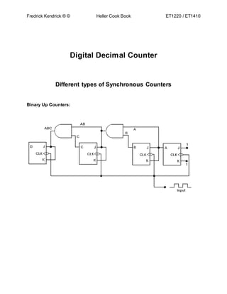
Different types of Synchronous Counters
Binary Up Counters:
- 3. Fredrick Kendrick ® © Heller Cook Book ET1220 / ET1410
Binary Up/Down Counters:
General Structure of a Synchronous Binary Counter:
There are two common ways in which a synchronous binary counter is structured.
These are, namely, the series carry synchronous counter and the parallel carry
synchronous counter. These two counters are illustrated
as follows:
- 5. Fredrick Kendrick ® © Heller Cook Book ET1220 / ET1410
Parallel Carry Synchronous Counter
Both counters depicted above are binary-up counters.
The T implies a T flip-flop. The flip-flop complements/toggles its output on the
rising edge of a clock pulse provided its enable (EN) input is high.
From the diagrams, it can be seen that the least significant bit Q0 toggles on
every clock pulse, and subsequent bits toggle when preceding bits are high. The
important distinction between the two counters is the way the EN signals
propagate from Q0 to Q3. This is illustrated by the highlighted paths. The signals
are propagated serially and in parallel (to each AND gate) in the first and second
case respectively.
The parallel carry scheme results in a much faster counter. This difference in
speed is accounted for by the delay encountered during the propagation of the
EN signals. To illustrate the worst case delay in both cases, we consider a
change in Q0 from 0 to 1. (see diagrams above)
- 6. Fredrick Kendrick ® © Heller Cook Book ET1220 / ET1410
In the series carry scheme, the time to propagate the change in Q0 must take into
account the propagation delays of the 3 AND gates (A, B, C). In the parallel carry
scheme, only the propagation delay of 1 AND gate has to be considered.
Therefore, the minimum clock period of the parallel scheme is shorter. Thus, the
parallel synchronous c arry counter operates at a greater maximum frequency.
This structure is believed to be the fastest synchronous binary counter structure.
In applications that require speed, this scheme is commonly used.
This structure does have limitations. From the diagrams, it can be seen that a
single flip-flop output(consider Q0) has to drive a number of subsequent AND
gates. The output current of a flip-flop may not be large enough to drive that
many gates. It becomes a problem when the counter gets bigger. To overcome
this, a tree of AND gates is usually used. How exactly this tree will look like is an
engineering choice. This choice will reflect the trade-off between speed
requirements and the constraint mentioned above.
Although the series carry scheme is slower, it does not suffer the same drawback
as the parallel carry scheme. This makes it a suitable basis for making big
counters. Its speed can be improved by using some form of Prescaling. This
technique will be considered in subsequent sections.
Reference:
Digital Fundamentals. By: Thomas L. Floyd. 3rd Edition. Pg. 432 – 435.
ISBN: 13: 978-0-13-235923-8. (LCCN: 2008920736). Pearson.
http://www.talkingelectronics.com/pay/PIC/PIC-Page27.html
http://picprojects.org.uk/projects/counter/counter.htm
http://www.talkingelectronics.com/projects/2DigitUpDwnCounter/2DigitUpDwnCo
unter-1.html
FredrickKendrick
December– 2014toMarch- 2015