
Recommended
More Related Content
What's hot
What's hot (20)
Similar to Introduction to communication systems
Similar to Introduction to communication systems (20)
More from HAmindavarLectures
More from HAmindavarLectures (13)
Recently uploaded
Recently uploaded (20)
Introduction to communication systems
- 1. Advanced Communication’s Theory Session 1 H.Amindavar February 2021 Analog vs. Digital Communications: 1. In Analog communication analog signal is used for information transmission. In Digital communication digital signal is used for information transmission. 2. Analog communication uses analog signal whose amplitude varies continuously with time for example from 0 to 100. Digital communication uses digital signal whose amplitude is of two levels either Low i.e., 0 or either High i.e., 1. 3. In Analog communication , signal gets affected by noise highly during transmission through communication channel. In Digital communication signal gets affected by noise less during transmission through communication channel. 4. In Analog communication only limited number of channels can be broadcasted simultaneously. Digital communication can broadcast large number of channels simultaneously. 5. In Analog communication error Probability is high. In Digital communication error Probability is low. 6. In Analog communication noise immunity is poor. In Digital communication noise immunity is good. 7. In Analog communication coding is not possible. In Digital communication coding is possible. Different coding techniques can be used to detect and correct errors. 8. Separating out noise and signal in Analog communication is not possible. Separating out noise and signal in Digital communication is possible. 9. Analog communication system is having complex hardware and is less flexible. Digital communication system is having less complex hardware and is more flexible. 1
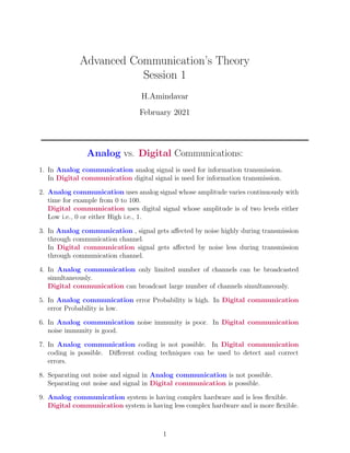
- 2. 10. In Analog communication for multiplexing Frequency Division Multiplexing (FDM) is used. In Digital communication for multiplexing Time Division Multiplexing (TDM) is used. 11. Analog communication system is low cost. Digital communication system is high getting cheaper by day. 12. Analog communication requires low bandwidth. Digital communication requires high bandwidth. 13. In Analog communication Power consumption is high. In Digital communication Power consumption is low. 14. In Analog communication is less portable.In Digital communication Portability is high. 15. In Analog communication there is no privacy or privacy is less so it’s not highly secured. In Digital communication Privacy is high so it is highly secured. 16. Analog communication does not assure an accurate data transmission. Digital communication assures a more accurate data transmission. 17. Synchronization problem: Digital communication Synchronization problem is eas- ier. A Digital communication system consists of : Formatting Source Encoding Channel Encoding Encryption Multiplexing Modulation Frequency Spreading Multiple Access Channel Source of Information Demultiple Access Frequency Despreading Demodulation Demultiplexing Channel Decoding Decryption Source Decoding deformatting Sink of Information Synchronization Figure 1: block diagram of a digital communication system • Digital Signal Formatting is the process of transforming information from one format into another. This is often used in many digital devices and for communication processes. A digital 2
- 3. system is a data technology that uses discrete (discontinuous) values. By contrast, non- digital (or analog) systems use a continuous range of values to represent information. Although digital representations are discrete, the information represented can be either discrete, such as numbers, letters or icons, or continuous, such as sounds, images, and other measurements of continuous systems. Formatting Lowpass Filterring Clipping Sampling Quantization Digitization Figure 2: Formatting • Encoding is the process of converting the data or a given sequence of characters, symbols, alphabets etc., into a specified format, for the secured transmission of data. • Decoding is the reverse process of encoding which is to extract the information from the converted format. • Encryption uses an algorithm to scramble, or encrypt data and then uses a key for the receiving party to unscramble, or decrypt, the information. The message contained in an encrypted message is referred to as plain-text. In its encrypted, unreadable form it is referred to as cipher-text. • The purpose of Channel Coding theory is to find codes which transmit quickly, contain many valid code words and can correct or at least detect many errors. While not mutually exclusive, performance in these areas is a trade off. So, different codes are optimal for different applications. The needed properties of this code mainly depend on the probability of errors happening during transmission. In a typical Compact Disc (CD), the impairment is mainly dust or scratches. • Modulation is a process of mixing a signal with a sinusoid to produce a new signal. ... The signal that is used in modulating the carrier signal(or sinusoidal signal) is known as the ”data signal” or the ”message signal”. It is important to notice that a simple sinusoidal carrier contains no information of its own. The most fundamental modulation schemes are: F Amplitude modulation (AM) is a modulation technique used in electronic communication, most commonly for transmitting messages with a radio carrier wave. In amplitude modulation, the amplitude (signal strength) of the carrier wave is varied in proportion to that of the message signal, such as an audio signal. 3
- 4. Modulation Analog Digital Amplitude Modulation(AM) Angle modulation frequency modulation(FM) phase modulation(PM) Constant Envelope Non constant Envelope FSK PSK ASK QAM Figure 3: Analog and Digital modulation schemes F Frequency modulation (FM) is the encoding of information in a carrier wave by varying the instantaneous frequency of the wave. The technology is used in telecommunications, radio broadcasting, signal processing, and computing. F Phase modulation (PM) is a modulation pattern for conditioning commu- nication signals for transmission. It encodes a message signal as variations in the instantaneous phase of a carrier wave. Phase modulation is one of the two principal forms of angle modulation, together with frequency modulation. F Quadrature amplitude modulation (QAM) is the name of a family of digital modulation methods and a related family of analog modulation methods widely used in modern telecommunications to transmit information. It conveys two analog message signals, or two digital bit streams, by changing (modulating) the amplitudes of two carrier waves, using the amplitude-shift key- ing (ASK) digital modulation scheme or amplitude modulation (AM) analog mod- ulation scheme. The two carrier waves of the same frequency are out of phase with each other by 90o , a condition known as orthogonality or quadrature. The transmitted signal is created by adding the two carrier waves together. At the receiver, the two waves can be coherently separated (demodulated) because of their orthogonality property. Another key property is that the modulations are low-frequency/low-bandwidth waveforms compared to the carrier frequency, which is known as the narrowband assumption. F In radio communications, single-sideband modulation (SSB) or single-sideband suppressed-carrier modulation (SSB-SC) is a type of modulation used to transmit information, such as an audio signal, by radio waves. by a refinement of amplitude modulation, it uses transmitter power and band- width more efficiently. Amplitude modulation produces an output signal the bandwidth of which is twice the maximum frequency of the original baseband signal. Single-sideband modulation avoids this bandwidth increase, and the power wasted on a carrier, at the cost of increased device complexity and more difficult tuning at the receiver. 4
- 5. • The Multiplexing divides the capacity of the communication channel into several logical channels, one for each message signal or data stream to be transferred. generally multiplexing combines several low-speed signals for transmission over a single high-speed connection. S1 S2 S3 R1 R2 R3 7 6 5 7 6 5 7 6 5 4 4 4 3 2 1 3 3 2 2 1 1 7 7 7 6 6 6 5 5 5 4 4 4 3 2 1 3 2 1 3 2 1 Channel Figure 4: Comprehensive scheme of multiplexing and demultiplexing A device that performs the multiplexing is called a multiplexer (MUX), and a device that performs the reverse process is called a demultiplexer (DEMUX or DMX). some multiplexing techniques are : F Time-division multiplexing (TDM) is a method of transmitting and receiving independent signals over a common signal path by means of synchronized switches at each end of the transmission line so that each signal appears on the line only a fraction of time in an alternating pattern. F In telecommunications, Frequency-Division Multiplexing (FDM) is a tech- nique by which the total bandwidth available in a communication medium is divided into a series of non-overlapping frequency bands, each of which is used to carry a separate signal. F Space Division Multiplexing (SDM) transmits different information in dif- ferent physical areas F In fiber-optic communications, Wavelength-Division Multiplexing (WDM) is a technology which multiplexes a number of optical carrier signals onto a single optical fiber by using different wavelengths of laser light. F Polarization-Division Multiplexing (PDM) is a physical layer method for multiplexing signals carried on electromagnetic waves, allowing two channels of information to be transmitted on the same carrier frequency by using waves of two orthogonal polarization states. F Orbital Angular Momentum multiplexing (OAM) is a physical layer method for multiplexing signals carried on electromagnetic waves using the orbital angu- 5
- 6. lar momentum of the electromagnetic waves to distinguish between the different orthogonal signals. Multiplexing Analog Digital Frequency division Multiplexing Wavelength division Multiplexing Time division Multiplexing Figure 5: Multiplexing techniques • Multiple access just means many can access at one time. Ethernet(Ethernet is a way of connecting computers and other network devices in a physical space. This is often referred to as a local area network or LAN. The idea of an Ethernet network is that computers and other devices can share files, information and data between each other efficiently. Ethernet was released in 1980) is multiple access, token ring(Token Ring is a computer networking technology used to build local area networks. It was introduced by IBM in 1984, and standardized in 1989 as IEEE 802.5. It uses a special three-byte frame called a token that travels around a logical ring of workstations or servers) is not. F The frequency-division multiple access (FDMA) channel-access scheme is the most standard analog system, based on the frequency-division multiplex- ing (FDM) scheme, which provides different frequency bands to different data streams. In the FDMA case, the frequency bands are allocated to different nodes or devices. An example of FDMA systems were the first-generation 1G cell-phone systems, where each phone call was assigned to a specific uplink frequency chan- nel, and another downlink frequency channel. Each message signal (each phone call) is modulated on a specific carrier frequency. F The time-division multiple access (TDMA) channel access scheme is based on the time-division multiplexing (TDM) scheme. TDMA provides differ- ent time slots to different transmitters in a cyclically repetitive frame structure. For example, node 1 may use time slot 1, node 2 time slot 2, etc. until the last transmitter when it starts over. An advanced form is dynamic TDMA (DTDMA), where an assignment of transmitters to time slots varies on each frame. F The code division multiple access (CDMA) scheme is based on spread spectrum, meaning that a wider radio channel bandwidth is used than the data rate of individual bit streams requires, and several message signals are transferred simultaneously over the same carrier frequency, utilizing different spreading codes. Per the Shannon–Hartley theorem(C = B log2(1 + SNR)), the wide bandwidth makes it possible to send with a signal-to-noise ratio of much less than 1 (less than 0 dB), meaning that the transmission power can be reduced to a level below the 6
- 7. level of the noise and co-channel interference from other message signals sharing the same frequency range. F space-division multiple access (SDMA) is a channel access method based on creating parallel spatial pipes (focused signal beams) using advanced antenna technology next to higher capacity pipes through spatial multiplexing and/or diversity, by which it is able to offer superior performance in radio multiple access communication systems (where multiple users may need to use the communication media simultaneously). • In telecommunication and radio communication, Spread-Spectrum techniques are methods by which a signal (e.g., an electrical, electromagnetic, or acoustic signal) generated with a particular bandwidth is deliberately spread in the frequency domain, resulting in a signal with a wider bandwidth. These techniques are used for a variety of reasons, including the establishment of secure communications, increasing resistance to natural interference, noise, and jamming, to prevent detection, and to enable multiple- access communications. some multiplexing techniques are : F In digital communications, chirp spread spectrum (CSS) is a spread spectrum technique that uses wideband linear frequency modulated chirp pulses to encode information. F In telecommunications, direct-sequence spread spectrum (DSSS) is a spread- spectrum modulation technique primarily used to reduce overall signal interfer- ence. The direct-sequence modulation makes the transmitted signal wider in bandwidth than the information bandwidth. F Frequency-hopping spread spectrum (FHSS) is a method of transmitting radio signals by rapidly changing the carrier frequency among many distinct fre- quencies occupying a large spectral band. The changes are controlled by a code known to both transmitter and receiver. FHSS is used to avoid interference, to prevent eavesdropping, and to enable code-division multiple access (CDMA) communications. • Time-hopping (TH) is a communications signal technique which can be used to achieve anti-jamming (AJ) or low probability of intercept (LPI). It can also refer to pulse-position modulation, which in its sim- plest form employs 2k discrete pulses (referring to the unique positions of the pulse within the transmission window) to transmit k bit(s) per pulse. To achieve LPI, the transmission time is changed randomly by varying the period and duty cycle of the pulse (carrier) using a pseudo-random sequence. The transmitted signal will then have intermittent start and stop times. Although often used to form hybrid spread-spectrum (SS) systems, TH is strictly speaking a non-SS technique. Spreading of the spectrum is caused by other factors associated with TH, such as using 7
- 8. pulses with low duty cycle having a wide frequency response. An exam- ple of hybrid SS is TH-FHSS or hybrid TDMA (time division multiple access). 8