Ch3 Design Considerations (Steel Bridges تصميم الكباري المعدنية & Prof. Dr. Metwally Abu-Hamd)
•
8 likes•1,799 views

This chapter discusses design considerations for steel bridges. It outlines two main design philosophies: working stress design and limit states design. The chapter then focuses on the working stress design method, which is based on the Egyptian Code of Practice for Steel Constructions and Bridges. It provides allowable stress values for various steel grades and loading conditions, including stresses due to axial, shear, bending, compression and tension loads. Design of sections is classified based on compact and slender criteria. The chapter also addresses stresses from repeated, erection and secondary loads.

Recommended
Recommended
More Related Content
What's hot
What's hot (20)
Similar to Ch3 Design Considerations (Steel Bridges تصميم الكباري المعدنية & Prof. Dr. Metwally Abu-Hamd)
Similar to Ch3 Design Considerations (Steel Bridges تصميم الكباري المعدنية & Prof. Dr. Metwally Abu-Hamd) (20)
More from Hossam Shafiq II
More from Hossam Shafiq II (20)
Recently uploaded
Recently uploaded (20)
Ch3 Design Considerations (Steel Bridges تصميم الكباري المعدنية & Prof. Dr. Metwally Abu-Hamd)
- 1. Chapter 3: Design Considerations CHAPTER 3 DESIGN CONSIDERATIONS
- 2. Steel Bridges CHAPTER 3 DESIGN CONSIDERATIONS 3.1 DESIGN PHILOSOPHIES The aim of design is that the bridge should sustain all loads and deformations liable to occur during its construction and use. A bridge design should satisfactorily accomplish the objectives of constructability, safety, and serviceability. Simply stated, a bridge design should permit safe structural erection as planned and be able to safely perform its intended function during its design life. The basis for structural design philosophies is the known stress-strain relationship of the material. It is usually assumed that the material is (a) homogeneous, i.e., has the same physical properties at all points, (b) obeys Hook's low, i.e., the material is linearly elastic, and (c) isotropic, i.e., has the same elastic properties in all directions. Two philosophies of design are in current use. The working stress design philosophy has been the principal one used during the past 100 years. According to this philosophy, a structural element is designed so that stresses computed under the action of working, or service, loads do not exceed predesignated allowable values. These allowable stresses are predescribed by a building code or specification to provide a factor of safety against attainment of some limiting stresses, such as the minimum specified yield stress or the stress at which buckling occurs. The computed stresses are well within the elastic range; i.e., stresses are proportional to strains. The other design philosophy is generally referred to as limit states design. This relatively recent term includes the methods commonly referred to as "ultimate strength design", "strength design", "plastic design", "load factor design", "limit design", and more recently, "load and resistance factor design (LRFD)". Limit states is a general term meaning "those conditions of a
- 3. Chapter 3: Design Considerations structure in which the structure ceases to fulfill the function for which it was designed". Those states can be divided into the categories of strength and serviceability. Strength (i.e., safety) limit states are plastic strength, buckling, fatigue, fracture, overturning and sliding. Serviceability limit states are those concerned with the use of the structure, such as deflection, vibration, permanent deformation and cracking. In limit states design, the strength limit states are dealt with by applying factors to the loadings, focusing attention on the failure modes (limit states) by making comparisons for safety at the limit state condition, rather than in the service load range as is done for working stress design. The design philosophy followed throughout this book is based on the latest edition (2001) of the Egyptian Code of Practice for Steel Constructions and Bridges (ECP). This code follows the allowable stress design method in which the bridge elements (members and connections) are proportioned on the basis of design loads and allowable stresses for the materials under service conditions. Values of the basic allowable stresses for different cases are given in Egyptian Building Code for the Design of Steel Structures and Bridges (ECP 2001) chapter 2 for members, chapter 3 for fatigue, and chapters 5, 6 for welded and bolted connections. The main sections of the code are summarized in this Chapter. 3.2 ALLOWABLE STRESSES FOR STRUCTURAL STEEL 3.2.1 GENERAL APPLICATION The following prescriptions, together with any other provisions stipulated in the special specifications, are intended to apply to the design and construction of steel bridges and buildings. The structural safety shall be established by computing the stresses produced in all parts and ascertaining that they do not exceed the allowable (working) stresses specified herein, when these parts are subjected to the most unfavourable conditions or combinations of the loads and forces according to the current Egyptian Code of Practice for Loads and Forces for Structural Elements. In applying the said prescriptions, approved scientific methods of design shall be used. Deflections shall be computed and they shall in no case exceed the limits herein after specified. 3.2.2 PRIMARY AND ADDITIONAL STRESSES 3.2.2.1 For the purpose of computing the maximum stress in a structure, the straining actions shall be calculated for two cases:
- 4. Steel Bridges Case I: Primary Stresses due to: Dead Loads + Live Loads or Superimposed Loads + Dynamic Effects + Centrifugal Forces. Case II: Primary and Additional Stresses due to: Case I + [(Wind Loads or Earthquake Loads), Braking Forces, Lateral Shock Effect, Change of Temperature, Frictional Resistance of Bearings, Settlement of Supports in addition to the Effect of Shrinkage and Creep of Concrete] 3.2.2.2 Stresses due to Wind Loads shall be considered as primary for such structures as towers, transmission poles, wind bracing systems, etc... 3.2.2.3 In designing a structure, members shall, in the first instance, be so designed that in no case the stresses due to case I exceed the allowable stresses specified in the present code. The design should then be checked for case II (primary + additional stresses), and the stresses shall in no case exceed the aforesaid allowable stresses by more than 20 %. 3.2.3 SECONDARY STRESSES Structures should be so designed, fabricated and erected as to minimize, as far as possible, secondary stresses and eccentricities. Secondary stresses are usually defined as bending stresses upon which the stability of the structure does not depend and which are induced by rigidity in the connections of the structure already calculated on the assumption of frictionless or pin-jointed connections. In ordinary welded, bolted or riveted trusses without sub-panelling, no account usually needs to be taken of secondary stresses in any member whose depth (measured in the plane of the truss) is less than 1/10 of its length for upper and lower chord members, and 1/15 for web members. Where this ratio is exceeded or where sub-panelling is used, secondary stresses due to truss distortion shall be computed, or a decrease of 15% in the allowable stresses prescribed in this code shall be considered. Bending stresses in the verticals of trusses due to eccentric connections of cross-girders shall be considered as secondary.
- 5. Chapter 3: Design Considerations The induced stresses in the floor members and in the wind bracing of a structure resulting from changes of length due to the stresses in the adjacent chords shall be taken into consideration and shall be considered as secondary. Stresses which are the result of eccentricity of connections and which are caused by direct loading shall be considered as primary stresses. For bracing members in bridges, the maximum allowable stresses shall not exceed 0.85 of the allowable stresses specified in this code if the bridge has not been considered as a space structure. 3.2.4 STRESSES DUE TO REPEATED LOADS Members and connections subject to repeated stresses (whether axial, bending or shearing) during the passage of the moving load shall be proportioned according to Chapter 3 of ECP 2001 which is summarized in section 3.3 of this Chapter. 3.2.5 ERECTION STRESSES Where erection stresses, including those produced by the weight of cranes, together with the wind pressure, would produce a stress in any part of structure in excess of 25 % above the allowable stresses specified in this code, such additional material shall be added to the section or other provision made, as is necessary, to bring the erection stresses within that limit. 3.2.6 ALLOWABLE STRESSES FOR STRUCTURAL STEEL 3.2.6.1 General Allowable stresses for structural steel shall be determined according to the grade of steel used. Structural sections shall be classified (depending on the maximum width-thickness ratios of their elements subject to compression) as follows: 1- Class 1. (compact sections): Are those which can achieve the plastic moment capacity without local buckling of any of its compression elements. 2- Class 2. (non- compact sections): Are those which can achieve the yield moment capacity without local buckling of any of its compression elements. The limiting width to thickness ratios of class 1 and 2 compression elements are given in Table 3.1.
- 6. Steel Bridges Table (3.1a) Maximum Width to Thickness Ratios for Stiffened Compression Elements =t t d=h-3t (t=t, f w d )w h wt dd twwt d 13 d wt
- 7. Chapter 3: Design Considerations Table (3.1b) Maximum Width to Thickness Ratios for Stiffened Compression Elements F in t/cmy 2
- 8. Steel Bridges Table (3.1c) Maximum Width to Thickness Ratios for Unstiffened Compression Elements Stress distribution in element Stress distribution in element c y
- 9. Chapter 3: Design Considerations Table (3.1d) Maximum Width to Thickness Ratios for Compression Elements 1. Compact 2. Non-Compact Refer also to "Outstand flanges" (Table 2.1c) 1. Compact 2. Non-Compact
- 10. Steel Bridges 3- Class 3. (slender sections): Are those which cannot achieve yield moment capacity without local buckling of any of its compression elements. When any of the compression elements of a cross-section is classified as class-3, the whole cross section shall be designed as class-3 cross section. 3.2.6.2 Allowable Stress in Axial Tension FR t On effective net area: FR tR = 0.58 FR y R………………………… 3.1 Grade of Steel FR t R(t/cmP 2 P) t 40 40 mm < t 100 mm St 37 1.4 1.3 St 44 1.6 1.5 St 52 2.1 2.0 3.2.6.3 Allowable Stress in Shear qR all 3.2.6.3.1 The allowable shear stress on the gross effective area in resisting shear is: qR allR = 0.35 FR yR………. 3.2 Grade of Steel qR allR (t/cmP 2 P) t 40 mm 40 mm < t 100 St 37 0.84 0.75 St 44 0.98 0.89 St 52 1.26 1.17 The effective area in resisting shear of rolled shapes shall be taken as the full height of the section times the web thickness while for fabricated shapes it shall be taken as the web height times the web thickness. In addition, the shear buckling resistance shall also be checked as specified in Clause 3.2.6.3.2 when:
- 11. Chapter 3: Design Considerations -For unstiffened webs: yw F 105 t d > ………………….…… 3.3 - For stiffened webs: y q w F K 45 t d > ………………….…… 3.4 Where KR qR =buckling factor for shear kR q R= 4.00 + 5.34 / αP 2 P α < 1 …… 3.5 kR q R= 5.34 + 4.00 / αP 2 P α > 1 …… 3.6 Where α = dR 1R / d & dR 1R = spacing of transversal stiffeners 3.2.6.3.2 Allowable Buckling Stress in Shear qR b Depending on the web slenderness parameter : λR q R = q yw K F 57 t/d ………………………………… 3.7 The buckling shear stress is : For λR q R≤R R0.8 qR bR = 0.35 FR y R……….………………… 3.8 0.8 < λR q R< 1.2 qR bR = (1.5 – 0.625 λR qR)R R( 0.35 FR y R) ……. 3.9 λR q R≥ 1.2 qR bR = qλ 0.9 (0.35 FR y R) …………………. 3.10
- 12. Steel Bridges 3.2.6.4 Allowable Stress in Axial Compression FR cR On gross section of axially loaded symmetric (having compact, non- compact or slender section) compression members in which the shear center coincides with the center of gravity of the section and meeting all the width- thickness ratio requirements of Clause 3.2.6.1: For λ = slenderness ratio = k l/ r < 100 : 2 c 4 y y 10 75.0F58.0 F58.0F )( λ − −= ….. 3.11 Grade of Steel FR cR (t/cmP 2 P) t 40 mm 40 mm < t100 mm St 37 FR cR = (1.4 – 0.000065λP 2 P) FR cR = (1.3– 0.000055λP 2 P) ….….3.12 St 44 FR cR = (1.6 – 0.000085λP 2 P) FR cR =(1.5– 0.000075λP 2 P) ……..3.13 St 52 FR cR = (2.1 – 0.000135λP 2 P) FR cR = (2.0– 0.000125λP 2 P) ……3.14 For all grades of steel For λ = kl/r ≥ 100 : FR cR = 7500/λP 2 P …………………….. 3.15 For compact and non-compact sections, the full area of the section shall be used, while for slender sections, the effective area shall be used. In case of sections eccentrically connected to gusset plates (e.g. one angle), unless a more accurate analysis is used, the allowable compressive stresses shall be reduced by 40% from Fc in case the additional bending stresses due to eccentricity are not calculated. 3.2.6.5 Allowable Stress in Bending FR b 2.6.5.1 Tension and compression due to bending on extreme fibers of “compact” sections symmetric about the plane of their minor axis: FR bR = 0.64 FR y R……….……………………….R 3.16
- 13. Chapter 3: Design Considerations Grade of Steel FR bR (t/cmP 2 P) t 40 mm 40 mm < t 100 mm St 37 1.54 1.38 St 44 1.76 1.63 St 52 2.30 2.14 In order to qualify under this section: 1- The member must meet the compact section requirements of Table 3.1. 2- The laterally unsupported length (LR uR) of the compression flange is limited by i- For box sections: fu bF 84 y L < 3.17 y 2 1 F/b)M M 84(137 fu L +≤ ii- For other sections y f u F 20b L ≤ 2.18 b C Fd L y f u 1380A ≤ Where bR fR is the compression flange width, MR 1R/MR 2R is the algebraic ratio of the smaller to the larger end moments taken as positive for reverse curvature bending, d is the web depth and CR bR is given in Equation 3.27. 3.2.6.5.2 Tension and compression due to bending on extreme fibers of doubly symmetrical I-shape members meeting the compact section requirements of
- 14. Steel Bridges Table 2.1(c), and bent about their minor axis; solid round and square bars; solid rectangular sections bent about their minor axis: FR bR = 0.72 FR yR ………………………… 3.19 3.2.6.5.3 Tension and compression on extreme fibers of rectangular tubular sections meeting the compact section requirements of Table 3.1(b), and bent about their minor axis: FR bR = 0.64 FR yR ……………………….… 3.20 3.2.6.5.4 Tension and compression on extreme fibers of box-type flexural members meeting the “non-compact” section requirements of Table 3.1(b): FR bR = 0.58 FR y R ……………………….……. 3.21 3.2.6.5.5 On extreme fibers of flexural members not covered by Clauses 3.2.6.5.1 – 3.2.6.5.4 : 1- Tension FR bt FR btR = 0.58 FR y R……………………………... 3.22 Hence, FR btR is taken as follows: 2- Compression FR bc I. When the compression flange is braced laterally at intervals exceeding LR uR as defined by Equations 3.17 or 3.18, the allowable bending stress in compression FR bcR will be taken as the larger value from Equations 3.23 and 3.24 or 3.25) with a maximum value of 0.58 FR y R: Grade of Steel FR bt R(t/cmP 2 P) t 40 mm 40 mm < t St 37 1.4 1.3 St 44 1.6 1.5 St 52 2.1 2.0
- 15. Chapter 3: Design Considerations i- For shallow thick flanged sections, for any value of L/rR TR, the lateral torsional buckling stress is governed by the torsional strength given by: yb fu 1ltb F58.0C A/d.L 800 F ≤= ………..…….3.23 ii- For deep thin flanged sections, the lateral torsional buckling stress is governed by the buckling strength given by: a- When y Tu y F C 188r/L F C 84 bb ≤≤ ,then : yy b 5 y 2 Tu F58.0F) C10x176.1 F)r/L( 64.0(2ltbF ≤−= …….……..3.24 b- When y Tu F C 188r/L b > , then: yb2 Tu F58.0C )r/L( 12000 2ltbF ≤= …………...……3.25 Alternatively, the lateral torsional buckling stress can be computed more accurately as the resultant of the above mentioned two components as: y 2 ltb 2 ltbtbl F58.0FFF 21 ≤+= ……….……………3.26 In the above Equations: Lu = Effective laterally unsupported length of compression flange = K. (distance between cross sections braced against twist, or lateral displacement of the compression flange in cm). K = Effective length factor (as given in Chapter 4 of Code) rR T = Radius of gyration about minor axis of a section comprising the compression flange plus one third of compression web area (in cms) AR f = (bR f R* tR fR) Area of compression flange (in cm2)
- 16. Steel Bridges D = Depth of web (in cm) Fy = Yield stress (t/cmP 2 P ) t R f = Compression flange thickness (in cm) CR b = Coefficient depending on the type of load and support conditions as given in Table 3.2. For cases of unequal end moments without transverse loads, (CR bR) can be computed from the expression : CR bR = 1.75 + 1.05 (MR 1R/MR 2R) + 0.3 (MR 1R/MR 2R)2 ≤ 2.3 ………………... 3.27 Where: (MR 1R/MR 2R) is the algebraic ratio of the smaller to the larger end moments taken as positive for reverse curvature bending. When the bending moment at any point within the un-braced length is larger than the values at both ends of this length, the value of (CR bR) shall be taken as unity. II- Compression on extreme fibres of channels bent about their major axis and meeting the requirements of Table 3.1. y fu ltb F58.0C )A/d.L( F b 800 ≤= .… 3.28 III. Slender sections which do not meet the non-compact section requirements of Table 3.1 shall be designed using the same allowable stresses used for non- compact sections except that the section properties used in the design shall be based on the effective widths bR eR of compression elements as specified in Table 3.3 for stiffened elements and Table 3.4 for unstiffened elements. The effective width is calculated using a reduction factor ρ as bR e R= ρ b Where: ρ = 1 2 /)05.015.0 p p ( ≤λψ−−λ ……………...……3.29 and p λ = normalized plate slenderness given by σ =λ K F 44 /tb y p ……………………… 3.30 M1 M2
- 17. Chapter 3: Design Considerations KR σ = Plate buckling factor which depends on the stress ratio ψ as shown in Tables 3.3 and 3.4. b = Appropriate width, (see Table 3.1) as follows : b = d for webs b = b for internal flange elements (except rectangle hollow sections) b = b-3t for flanges of rectangle hollow sections. b = c for outstand flanges b = b for equal leg angles b = b or (b+h)/2 for unequal leg angles t = relevant thickness. Table (3.2) Values of Coefficients K and CR b
- 18. Steel Bridges Simple Simple Fixed Fixed Fixed Simple Simple Fixed Fixed Warping Restrained Restrained Bending Moment End Restraint About Y-axis Loading Daigram 1.0 1.0 1.50 2.10 0.5 1.0 0.5 1.0 0.5 Simple Simple Fixed 1.70 1.04 0.90 1.35 1.07 1.0 1.0 0.5 1.0 0.5 0.5 1.0 2.30 1.13 1.00 1.30 1.00 1.00 2.30 Effective Length Factor K Cb
- 19. Chapter 3: Design Considerations Table (3.3) Effective Width and Buckling Factor for Stiffened Compression Elements be1 b e2b be1 b be2 e e = /(1- ) b = 2 b /(5- ) b = 0.4 b b b e1 = 0.6 be2 = be c b b = be2 e = b e1 e b be1 Stress Distribution bbe1 e2 b 1 Effective Width b for e e= b0.5e1b b = b e2 0.5 b = be e p f f 2 f 1 f 2 1f f 2 bc tb < 1p 2 2 1ff Buckling Factor k 01 1> >0 8.2 1.05+4.0 7.81 -1 23.9 0 > > -1 7.81-6.29 +9.78 2 -1> >-2 5.98(1- )2 [(1+ ) + 0.112(1- ) ] +(1+ ) For 1 > > -1: k 16 2 2 0.5 + = ( -0.15 - 0.05 )/
- 20. Steel Bridges Table (3.4) Effective Width and Buckling Factor For Unstiffened Compression Elements 0.43 tb Buckling factor k c 0.57-0.210.57 0.85 1 > +0.07 > 0: be be bc eb >0 + 0.34 Buckling factor 0.43k 1 0.578 1> +17.11.70 0 1.7-5 0 > 23.8 >-1 -1 c Stress Distribution = ( -0.15 -0.05 ) / < 1 Effective Width b for p e 2 p be c be cb c 1 > > 0: eb 3.2.6.6 Allowable Crippling Stress in Web Fcrp Web crippling is a localised yielding that arises from high compressive stresses occurring in the vicinity of heavy concentrated loads. On the web of rolled shapes or built-up I-sections, at the toe of the fillet, the allowable crippling stress shall not exceed:
- 21. Chapter 3: Design Considerations R n n+2k n+k t k R k w Fcrp = 0.75 Fy …………………………………….. 3.31 The crippling stress (fcrp) at the web toes of the fillets resulting from concentrated loads (R) not supported by stiffeners shall be calculated from the following Equations: for interior loads )k2n(t R f w crp + = ………………… 3.32 for edge loads )kn(t R f w crp + = …………………… 3.33 3.2.6.7 Combined Stresses 3.2.6.7.1 Axial Compression and Bending Members subjected to combined axial compression (N) and simple bending moment (M) about the major axis shall be proportioned to satisfy the following interaction Equation: 0.1A F f A F f F f 2 bcy by 1 bcx bx c ca ≤++ ……….. 3.34 Grade of Steel Fcrp (t/cmP 2 P) t 40 mm 40 mm < t St 37 1.8 1.6 St 44 2.1 1.9 St 52 2.7 2.5
- 22. Steel Bridges For cases when fca/ Fc < 0.15, A1 = A2 = 1.0. otherwise: ) F f 1( C A Ex ca mx 1 − = , ) F f 1( C A Ey ca my 2 − = fca = Actual compressive stress due to axial compression. Fc = The allowable compressive stress, as-appropriate, prescribed in Clause 3.2.6.4. fbx, fby = The actual bending stresses based on moments about the x and y axes respectively. Fbcx,Fbcy = The allowable compressive bending stresses for the x and y axes respectively, considering the member loaded in bending only as prescribed in Clause 3.2.6.5. FEx, FEy = The Euler stress divided by the factor of safety for buckling in the x and y directions respectively (t/cmP 2 P). λ = 2 x Ex 7500 F , λ = 2 y 7500 FEy ………………………..3.35 Cm = Moment modification factor, and to be taken according to the following: a- For frames prevented from sway without transverse loading between supports Cm = 0.6 - 0.4 (M1/ M2) > 0.4 where the end moments M1 and M2 carry a sign in accordance with end rotational direction; i.e. positive moment ratio for reverse curvature and negative moment ratio for single curvature (M2 > M1). b- For frames, prevented from sway, with transverse lateral loading between supports, Cm may be taken: i- For members with moment restraint at the ends Cm = 0.85. ii- For members with simply supported end Cm = 1.0. c- For frames permitted to sway, Cm= 0.85.
- 23. Chapter 3: Design Considerations d- In addition, sections at critical locations, e.g. at member ends, shall satisfy the following Equation: 01. bcy F by f bcx F bx f c F ca f ≤++ …………………...………… 3.36 3.2.6.7.2 Axial Tension and Bending Members subjected to combined axial tension "N" and bending moment "M" shall be proportioned to satisfy the following conditions: fN + fM ≤ 0.58 Fy ……………………………………. 3.37 Where: fN = the tensile stress due to the axial tensile force (N)=N/Anet fM = the maximum tensile stress due to the bending moment (M). In addition, the compressive bending stress alone shall be checked against the lateral torsional buckling stress. 3.2.6.8 Equivalent Stress fe Whenever the material is subjected to axial and shear stresses, the equivalent stress (fe) must not exceed the permitted stresses given in this code plus 10%, and the equivalent stress shall be calculated as follows: all 22 e F1.1q3ff ≤+= ……………………………… 3.38 3.2.7 ALLOWABLE STRESSES IN BEARINGS AND HINGES 3.2.7.1 Table 3.5 gives the allowable stresses in (t/cmP 2 P) in the parts of bearings and hinges made of cast iron, cast steel, and forged steel subject to bending or compression. These allowable stresses may be exceeded by 20% when the maximum combination of primary and additional stresses is taken into account.
- 24. Steel Bridges Table (3.5) Allowable Stresses in Parts of Bearings and Hinges Material Primary Stresses (t/cmP 2 P) 2BBending 4BCompression Cast steel CST 55 1.80 1.80 Forged steel FST 56 2.00 2.00 Cast Iron CI 14: Tension Compression 0.30 0.60 0.90 0.90 3.2.7.2 According to Hertz formula, the bearing pressure between a cylinder and a plane surface is calculated as follows: VE 0.423 max f = …………. 3.39 Where: fmax = Maximum actual bearing pressure at the surface of contact (t/cmP 2 P). r = Radius of cylinder or sphere (cm). E = Young's modulus (t/cmP 2 P). V = Maximum load on bearing (ton). ℓ = Bearing length (cm). For fixed, sliding, and movable bearings with one or two rollers, the allowable bearing stresses (t/cmP 2 P) shall be as given below, when the surface of contact between the different parts of a bearing are lines or points and when their design is carried out according to Hertz formula, assuming these bearings are subjected only to the primary stresses designated in Clause 3.2.2.1. 5BMaterial Allowable Bearing Stress (t/cmP 2 P) For Cast Iron Cl 14 5.00 For Rolled Steel St 44 6.50 For Cast Steel CST 55 8.50 For Forged Steel FST 56 9.50
- 25. Chapter 3: Design Considerations 3.2.7.3 The allowable load V (ton) on a cylindrical expansion roller shall not exceed the following values: Where: d = Diameter of roller (cm). ℓ = Length of roller (cm). In the case of movable bearings with more than two rollers, where the compressive force affecting the said rollers cannot be equally shared by all their parts, the aforesaid allowable reactions shall be increased by 20%. 3.2.7.4 When bearings are provided with cylindrical cast steel knuckle pins, the diameter (d) of the pins shall be given by the formula: V . 3 4 d = ……………………………… 3.40 Where: d = Diameter of pin (cm). V = Vertical load (ton). ℓ = Length of pin (cm). The bearing pressure between pins made of cast or forged steel and the gusset plates shall not exceed 2.40 t/cmP 2 P. Material Allowable Reaction (ton) Rolled steel St 37 0.040 d.ℓ Rolled steel St 44 0.055 d.ℓ Cast steel CST 55 0.095 d.ℓ Forged steel FST 56 0.117 d.ℓ
- 26. Steel Bridges 3.3 FATIGUE 3.3.1 General A bridge member may respond to applied loads in one of the following three ways, see Fig 3.1: (a) deform elastically, or (b) deform plastically, or (c) break. Since steel is a ductile material, failure of steel members is normally preceded by a considerable amount of elastic or plastic deformations. This amount depends on the magnitude of applied loads (below or above the yield level) and on the repetitive and cyclic nature of the load. Elastic Yield Failure Fig. 3.1 Behaviour Stages: (a) Elastic, (b) Plastic, (c) Failure Sometimes, however, certain types of steel members may fail suddenly in the form of brittle fracture. It was found that this failure mode starts from the presence of very small defect and cracks in the member during fabrication due to rolling, cutting, drilling, and or welding, see Fig. 3.2. The presence of these defects causes stress concentration around them as shown in Fig. 3.3a for a plate with a hole and in Fig. 3.3b at a fillet weld toe. The stress concentration around the defects causes them, although initially undetected, to increase in size and eventually propagate to failure when the member is subjected to a large number of stress cycles, see Fig 3.4. In order to determine the design parameters that can prevent the occurrence of this brittle failure, Fracture Mechanics concepts can be applied to arrive at the fatigue strength of different bridge components; e.g., members and connections. Control of fatigue failure is then achieved through efficient design and detailing.
- 27. Chapter 3: Design Considerations a) Porosity / Slag Inclusion b) Lack of Fusion c) Weld Cracks Fig 3.2 Possible Defects Causing Fatigue Failure
- 28. Steel Bridges Fig 3.3a Stress Concentration in a Plate with Hole Fig 3.3b Stress Concentration at Fillet Weld Toe Fig 3.3c Crack Initiation and Propagation
- 29. Chapter 3: Design Considerations Fig 3.4 Cracks Causing Fatigue Failure due to Weld Defects This section presents a general method for the fatigue assessment of structures and structural elements that are subjected to repeated fluctuations of stresses. Members subjected to stresses resulting from fatigue loads shall be designed so that the maximum stresses do not exceed the basic allowable stresses under static load conditions and that the stress range, see definition below, does not exceed the allowable fatigue stress range given in this section.
- 30. Steel Bridges 3.3.2 DEFINITIONS Fatigue: Damage in a structural member through gradual crack propagation caused by repeated stress fluctuations. Design Life: The period in which a structure is required to perform safely with an acceptable probability that it will not fail or require repair. Stress Range: The algebraic difference between two extreme values or nominal stresses due to fatigue loads, see Fig. 3.5. This may be determined through standard elastic analysis. Fatigue Strength: The stress range determined form test data for a given number of stress cycles. Fatigue Limit: The maximum stress range for constant amplitude cycles that will not form fatigue cracks. Detail Category: The designation given to a particular joint or welded detail to indicate its fatigue strength. The category takes into consideration the local stress concentration at the detail, the size and shape of the maximum acceptable discontinuity, the loading condition, metallurgical effects, residual stresses, fatigue crack shapes, the welding procedure, and any post-welding improvement. Fig. 3.5a) Stress Definitions Related to Fatigue, Constant Stress Cycles
- 31. Chapter 3: Design Considerations Fig. 3.5b) Variable Amplitude Stress History Fig. 3.5c) Various Patterns of Stress Variation 3.3.3 BASIC PRINCIPLES RELATED TO FATIGUE 1- The differences in fatigue strength between grades of steel are small and may be neglected. 2- The differences in fatigue damage between stress cycles having different values of mean stress but the same value of stress range may be neglected. 3- Cracks generally occur at welds or at stress concentration due to sudden changes of cross-sections. Very significant improvements in fatigue strength can be achieved by reducing the severity of stress concentrations at such points.
- 32. Steel Bridges 4- Members subjected to stresses resulting from wind forces only, shall be designed so that the maximum unit stress does not exceed the basic allowable unit stress given in the Code. 5- Cracks that may form in fluctuating compression regions are self- arresting. Therefore, these compression regions are not subjected to fatigue failure. 6- When fatigue influences the design of a structure, details should be precisely defined by the designer and should not be amended in any way without the designer’s prior approval. Similarly, no attachments or cutouts should be added to any part of the structure without notifying the designer. 7- Structures in which the failure of a single element could result in a collapse or catastrophic failure should receive special attention when fatigue cracks are a possibility. In such cases, the allowable stress ranges shall be limited to 0.8 times the values given in Table 3.2 or in Figure 3.1. 8- Slotted holes shall not be used in bolted connections for members subjected to fatigue. 3.3.4 Factors Affecting Fatigue Strength The fatigue strength of the structural elements depends upon: 1- The applied stress range resulting from the applied fatigue loads. 2- The number of stress cycles. 3- The detail category of the particular structural component or joint design. 3.3.5 Fatigue Loads 1- Roadway Bridges: The fatigue loads used to calculate the stress range are 50% of the standard design live loads including the corresponding dynamic effect. 2- Railway Bridges: The fatigue loads used to calculate the stress range are the full standard design live loads. For bridges carrying both trucks and trains, the fatigue load is the combined effect of the full railway live load and 60% of the traffic live loads.
- 33. Chapter 3: Design Considerations 3.3.6 Fatigue Assessment Procedure 1- The fatigue assessment procedure should verify that the effect of the applied stress cycles expected in the design life of the structure is less than its fatigue strength. 2- The effect of applied stress cycles is characterized by the maximum stress range (fsra). The maximum stress range can be computed from the applied fatigue loads using an elastic method of analysis. The fatigue loads should be positioned to give the maximum straining actions at the studied detail. In some structures such as bridges and cranes, consideration should be given to possible changes in usage such as the growth of traffic, changes in the most severe loading, etc. 3- In non-welded details or stress relieved welded details subjected to stress reversals, the effective stress range to be used in the fatigue assessment shall be determined by adding the tensile portion of the stress range and 60% of the compressive portion of the stress range. In welded details subjected to stress reversals, the stress range to be used in the fatigue assessment is the greatest algebraic difference between maximum stresses. 4- The fatigue strength of a structural part is characterized by the allowable stress range (Fsr) which is obtained from Table 3.2 for the specified number of constant cycles and the particular detail category. 5- The number of constant stress cycles to be endured by the structure during its design life is given in Table 3.6a for roadway bridges and Table 3.6b for railway bridges. The number of cycles given in Tables 3.6a and 3.6b is subject to modifications according to the competent authority requirements. Table (3.6a) Number of Loading Cycles – Roadway Bridges Type of Road ADTT P * Number of Constant Stress Cycles (N) Longitudinal Members Transverse Members Major Highways and Heavily Traveled Main Roads ≥ 2500 2,000,000 Over 2,000,000 < 2500 500,000 2,000,000 Local Roads and Streets 100,000 500,000 P * P ADTT = Average Daily Truck Traffic for 50 years design life
- 34. Steel Bridges Table (3.6b) Number of Loading Cycles – Railway Bridges Member Description Span Length (L) (m) Number of Constant Stress Cycles (N) Class I Longitudinal flexural members and their connections, or truss chord members including end posts and their connections. L > 30 500,000 30 ≥ L ≥ 10 2,000,000 L < 10 Over 2,000,000 Class II Truss web members and their connections except as listed in class III Two tracks loaded 200,000 One track loaded 500,000 Class III Transverse floor beams and their connections or truss verticals and sub- diagonals which carry floor beam reactions only and their connections Two tracks loaded 500,000 One track loaded over 2,000,000 6- In detailing highway bridges for design lives greater than 50 years, the fatigue loads should be increased by a magnification factor, M, given by the following Table: No. of Years 50 80 100 120 Magnification Factor, M 1.00 1.10 1.15 1.20 7- Each structural element has a particular detail category as shown in Table 7.3 The classification is divided into four parts which correspond to the following four basic groups: Group 1: non-welded details, plain materials, and bolted plates. Group 2: welded structural elements, with or without attachments. Group 3: fasteners (welds and bolts). Group 4: Orthotropic Deck Bridges. 8- When subjected to tensile fatigue loading, the allowable stress range for High Strength Bolts friction type shall not exceed the following values: Number of Cycles Allowable Stress Range Fsr (t/cmP 2 P) Bolts Grade 8.8 Bolts Grade 10.9 N ≤ 20,000 2.9 3.6 20,000 < N ≤ 500,000 2.6 3.2 500,000 < N 2.0 2.5
- 35. Chapter 3: Design Considerations Table (3.7) Allowable Stress Range (Fsr) for Number of Constant Stress Cycles (N) Fsr (t/cmP 2 P) 100,000 500,000 2,000,000 Over 2,000,000 3BA 4.30 2.52 1.68 1.68 B 3.42 2.00 1.26 1.12 B’ 2.77 1.52 1.02 0.85 C 2.48 1.45 0.91 0.70 D 1.92 1.12 0.71 0.49 E 1.53 0.89 0.56 0.32 E’ 1.11 0.65 0.41 0.18 F 0.72 0.52 0.40 0.36 0.1 1 10 10,000 100,000 1,000,000 10,000,000 100,000,000 Number of Constant Stress Cycles StressRange 2 ) A B B' C D E E' F Fig. 3.1. Stress Range Versus Number of Constant Stress Cycles
- 36. Steel Bridges Table (3.8) Classification of Details Group 1: Non-Welded Details 1.1. Base metal with rolled or cleaned surfaces; flame cut edges with a surface roughness less than 25 Description Illustration Class 1.2. Base metal with sheared or flame cut edges with a surface roughness less than 50 2.1. Base metal at gross section of high strength bolted slip resistant (friction) connections, except axially loaded joints which induce out of plane bending in connected material. 2.2. Base metal at net section of fully tensioned high strength bolted bearing type connections 2.3. Base metal at net section of other mechanically fastened joints (ordinary bolts & rivets). 3. Base metal at net section of eye-bar head or pin plate. net section area net section area
- 37. Chapter 3: Design Considerations Group 2: Welded Structural Elements 4.1. Base metal in members without attachments, built up plates or shapes connected by continuous full penetration groove welds or by continuous fillet welds carried out from both sides without start stop positions parallel to the direction of applied stress. Description Illustration Class 4.2. Same as (4.1.) with welds having stop - start positions. 4.3. Base metal in members without attachments, built-up plates or shapes connected by continuous full penetration groove welds with backing bars not removed, or by partial penetration groove welds parellel to the direction of applied stress. 5. Base metal at continuous manual longitudinal fillet or full penetration groove welds carried out from one side only. A good fit between flange and web plates is essential and a weld preparation at the web edge such that the root face is adequate for the achievement of regular root penetration. 6. Base metal at zones of intermittent longitudinal welds with gap ratio g/h < 2.5 B B C D B 7. Base metal at zones containing copes in longitudinally welded T- joints. D 8. Base metal at toe of welds on girder webs or flanges adjacent to welded transverse stiffeners. C
- 38. Steel Bridges 9.1. Base metal and weld metal at full penetration groove welded splices ( weld made from both sides ) of parts of similar cross sections ground flush, with grinding in the direction of applied stress and weld soundness established by radiographic or ultrasonic inspection. Description Illustration Class 9.2. Same as (9.1.) but with reinforcement not removed and less than 0.10 of weld width. 9.3. Same as (9.2.) with reinforcement more than 0.10 of weld width. 10.1. Base metal and weld metal at full penetration groove welded splices (weld made from both sides) at transitions in width or thickness, with welds ground to provide slopes no steeper than 1 to 2.5 with grinding in the direction of applied stress, and with weld soundness established by radiographic or ultrasonic inspection. 10.2. Same as (10.1.) but with reinforcement not removed and less than 0.10 of weld width. B C C D 10.3. Same as (10.2.) with slopes more than 1 to 2.5 D 10.4. Same as (10.1.) to (10.3.) but with welds made from one side only. E B
- 39. Chapter 3: Design Considerations 11.1. Base metal and weld metal at transverse full penetration groove welded splices on a backing bar. The end of the fillet weld of the backing strip is more than 10 mm from the edges of the stressed plate Description Illustration Class 12.2 Base metal at ends of partial length welded cover plates wider than the flange without end welds. 15.1. Base metal at full penetration weld in cruciform joints made of a special quality weld. D 15.2. Same as (15.1) with partial penetration or fillet welds of normal quality. 11.2. Same as (11.1) with the fillet weld less than 10 mm from the edges of the stressed plate. E t= thickness t= thickness E E 14. Base metal at members connected with transverse fillet welds. D 12.1. Base metal at ends of partial length welded cover plates narrower than the flange having square or tapered ends, with or without welds across the ends or wider than the flange with welds at the ends. Flange thickness < 20 mm 13. Base metal at axially loaded members with fillet welded connections. t < 25 mm t > 25 mm Category E or E E , E C E Flange thickness > 20 mm E ,
- 40. Steel Bridges 16. Base metal at plug or slot welds. Description Illustration Class 17. Base metal and attachment at fillet welds or partial penetration groove welds with main material subjected to longitudinal loading and weld termination ground smooth R > 50 mm R < 50 mm 18. Base metal at stud- type shear connector attached by fillet weld or automatic end weld. 19.1. Base metal at details attached by full penetration groove welds subject to longitudinal loading with weld termination ground smooth. Weld soundness established by radiographic or ultrasonic inspection R > 610 mm 610 mm > R > 150 mm 150 mm > R > 50 mm R < 50 mm D C 19.2. Same as (19.1.) with transverse loading, equal thickness, and reinforcement removed. R > 610 mm 610 mm > R > 150 mm 150 mm > R > 50 mm R < 50 mm E B C D E C E D B
- 41. Chapter 3: Design Considerations Description Illustration Class 19.3. Same as (19.2.) but reinforcement not removed R > 610 mm 19.4. Same as (19.2.) but with unequal thickness R > 50 mm R < 50 mm C D D D E C E D 19.5. Same as (19.4.) but with reinforcement not removed and for all R 21. Base metal at detail attached by fillet welds or partial penetration groove welds subject to longitudinal loading a < 50 mm 50 mm< a <12t or 100 mm a >12t or 100 mm (t<25 mm) a >12t or 100 mm (t>25 mm) E E E C E , 20. Base metal at detail attached by full penetration groove welds subject to longitudinal loading 50-mm< a <12t or 100 mm a >12t or 100 mm (t<25 mm) 610 mm > R > 50 mm 150 mm > R > 50 mm R > 50 mm a >12t or 100 mm (t>25 mm)
- 42. Steel Bridges Group 3: Fasteners (Welds and Bolts) 22.1. Weld metal of full penetration groove welds parallel to the direction of applied stress ( weld from both sides) Description Illustration Class 22.2. Same as (22.1.) but with weld from one side only. 23.1 Weld metal of continuous manual or automatic longitudinal fillet welds transmitting continuous shear flow. 26. Shear stress on nominal area of stud-type shear connectors.(Failure in the weld or heat affected zone.) B C C 28. Bolts and threaded rods in tension (on net area) F 22.3. Weld metal of partial penetration transverse groove weld based on the effective throat area of the weld. F F 23.2 Weld metal of intermittent longitudinal fillet welds transmitting a continuous shear flow. E , E , 24. Transversally loaded fillet welds. 25. Shear on plug or slot welds. F F 27.2. Rivets and ordinary bolts in shear. D 23.3 Weld metal at fillet welded lap joints. D 27.1. High strength bolts in single or double shear (fitted bolt of bearing type).
- 43. Chapter 3: Design Considerations Group 4: Orthotropic Deck Bridges Description Illustration Class 29.1. Base metal at continuous longitudinal rib with or without additional cutout in cross girder. ( Bending stress range in the rib) t < 12mm 29.2. Same as (29.1.) t > 12mm 32.1. Base metal at rib joints made of full penetration weld without backing plate. All welds ground flush to plate surface in the direction of stress. Slope of thickness transition < 1:4. (Bending stress range in the rib) B D 31. Base metal at rib joints made of full penetration weld with backing plate.( Bending stress range in the rib) D C E 30. Base metal at separate longitudinal ribs on each side of the cross girder. (Bending stress range in the rib) D 32.2. Same as (32.1.) with weld reinforcement < 0.2 C 33. Base metal at connection of continuous longitudinal rib to cross girder. (Equivalent stress range in the cross girder web). 34.1. Weld metal at full penetration weld connecting deck plate to rib section. 34.2. Weld metal at fillet weld connecting deck plate to rib section. E E
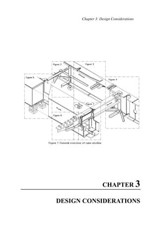
- 44. Steel Bridges 3.3.7 Examples of weld detail classifications In order to assist a designer in selecting the correct detail category, this section presents a case study of a particular civil engineering structure, and shows how the details can be classified. The case study comprises an imaginary steel bridge, as shown in an exploded isometric view in Figure 1. In order to illustrate as many different details as possible, two forms of construction are shown with a box girder on the left hand side and a braced plate girder on the right hand side. Furthermore, there are differences between the two sides in bearing arrangement, connection of cross girders, etc. It is not suggested that these arrangements, nor even some of the details, are necessarily representative of good design practice; they are presented for the purpose of illustrating a point of discussion. This imaginary structure is then subdivided as shown in Figure 1 into several close-up details in Figures 2 - 7, which in some cases are further subdivided where necessary for clarity. The detailed figures indicate the direction of principal stress, and the potential crack location and direction; the category into which the detail should be classified according to European Code is shown as a number in a circle beside the detail. Examples of Weld Detail Group Classifications
- 45. Chapter 3: Design Considerations Notes on Fig. 2: a. This detail should generally be avoided (it is usually better, and probably easier, to detail the longitudinal stiffeners passing through "mouseholes" in the transverse stiffeners). b. The category of 112 shown is the "standard" one for automatic fillet welding carried out from both sides, but containing stop-start positions. If it contained no stop-start positions it could be upgraded to category 125, or even 140 if a specialist inspection shows that the welds are free from significant flaws; conversely, if the fillet were placed manually, it would be downgraded to category 100. c. Stresses should be calculated using the gross section for slip resistant connections, or the net section for all other connections. The effects of eccentricity in the connection should be taken into account when calculating the stresses in a single-sided connection. d. This detail (at the termination of a longitudinal stiffener) may be treated for cracking in the main plate as a long (>100m) longitudinal attachment within the width of a plate with a non-load carrying weld. Note that the weld may also require checking in shear, with the stress range calculated from the weld throat area. e. The gusset plate attached as shown to the leg of the angle may be treated as a cover plate wider than the flange (with the leg of the angle representing the flange). Provided all plate thicknesses are 20mm or less, this is category 50* for cracking in the angle; this reduces to 36* if thicknesses exceed 20mm. The weld should be continued down the leg of the angle, and ground to remove undercut if necessary
- 46. Steel Bridges
- 47. Chapter 3: Design Considerations Notes on Fig. 2a: a & b These details show how cracks may grow in different directions in an area of complex geometry and stress distribution. Considerations are similar to Figure 2, note e, but the bearing plate > 20mm thick and so the category for plate cracking is reduced to 36*. c. See Figure 2, note b; as the weld to the bearing plate will almost certainly be placed manually, the lower category of 100 is used. d. The category of the plate edge depends on the method of production; if it is a rolled flat the category could be increased to 160, or if machine flame cut with subsequent machining to 140. The indicated category of 125 is for a machine flame cut edge without subsequent machining. It should contain no repairs by weld infill. e. As for Figure 2, note b. f. As for Figure 2, note c. g. The category of this weld has been reduced from the 71 or 80 shown for web stiffeners since the stiffener is shown flush with the edge of the plate
- 48. Steel Bridges
- 49. Chapter 3: Design Considerations Notes on Fig. 3: a. This is a rather poor detail, since because of the taper in the flange a good fit cannot be guaranteed above the backing flat; hence the low category of 50. b. At the top of the butt weld, provided the "reinforcement" does not exceed 0.1 times the width of the weld bead, the category is 90; up to 0.2 it would be 80. Run off pieces should also be used. (If the weld is ground flush the category could be 125 or higher). Normally there would be little point in making the category of the top surface much higher than that of the bottom, unless the eccentricity arising from the change of plate thickness results in a higher stress range at the top. c. The comparatively high category of this weld is only true for a gusset plate with a generous radius as drawn ( > 150mm, and also > (width of main plate)/3). The radius has to be formed by initial machining or gas cutting, with subsequent grinding of the weld area parallel to the direction of stress. If the radius < (width of main plate)/6 the category falls to 45*, and between the two limits above to 71. d. It should be noted that the weld should be held back 10mm from the end of the gusset. As it is a single sided connection, the effects of eccentricity should be considered. e. The calculation of the stress in the main plate requires care, and in a single sided application as shown may have to allow for eccentricity. f. This is a standard "bad" detail for increasing the area of a plate. The plates in the example are not thicker than 20mm so the category is 50*; above this thickness the category is reduced to 36*. Contrary to what may be thought, tapering the cover plate as shown, or rounding its end, does not, in itself, improve the detail; however, a special detail with tapering welds and chamfered cover plates, being developed by German Railways, may raise the category to 80. g. This is a two sided butt weld, with the surface ground flush. Significant quality control and inspection is required to permit the use of this high category. h. As for Figure 2, note d.
- 50. Steel Bridges
- 51. Chapter 3: Design Considerations Notes on Fig. 4: a. This is a butt weld, without backing flat and ground flush, between plates of different thickness. Provided the difference in thickness is taken up by tapering the thicker member with a slope of not greater than 1:4, this still qualifies as a category 112 weld. b. As Figure 3, note g. c. As Figure 3, note g, but it is a single sided weld without backing flat and because very high quality of execution and inspection is specified, the category can be raised to 125. d. As for Figure 2, note c, but as the connection is double sided no eccentricity occurs.
- 52. Steel Bridges Notes on Fig. 4a: a. This is the standard detail for fillet welds in shear. The stress range should be calculated from the weld throat area. b. As for Figure 2, note c, but as the connection is double sided no eccentricity occurs. Note that crack begins from edge of washer. c. As for Figure 2, note c, but as the connection is double sided no eccentricity occurs. Note carefully that direction of crack is related to direction of stress.
- 53. Chapter 3: Design Considerations Notes on Fig. 4b: a & b Are both as for Figure 2, note c, but note that the direction of stress, and hence the direction of cracking, may differ from hole to hole. c. As for Figure 4a, note a. d. Note that the stiffener should terminate at least 10mm above the flange, and the weld should be returned round the bottom of the stiffener. Some recent evidence suggests that out-of-plane flexure of the web plate at the termination of the stiffener could degrade this detail, but research continues on it.
- 54. Steel Bridges
- 55. Chapter 3: Design Considerations Notes on Fig. 5: a. As for Figure 4a, note a. Note crack propagating across direction of principal tensile stress. b. This is the standard detail for the welding of diaphragms in box girders to the webs and flanges, where the diaphragm thickness is not greater than 12 mm. If the thickness were greater the category would be reduced to 71. c. This is the standard detail for corner welds of box girders. Note that a good fit between flange and web is essential, so that a one sided weld can be placed without blow through. In certain forms of construction and loading this weld is also prone to bending about its longitudinal axis due either to local traffic loading or distortional effects in the box girder. It is virtually impossible to give a category for such effects, and considerable experience is necessary. d. As for Figure 2a, note d. e. See Figure 2, note b. As the weld will be placed manually, it is category 100.
- 56. Steel Bridges
- 57. Chapter 3: Design Considerations Notes on Fig. 5a: a. This weld is being stressed by flexure of the web plate and is not readily classifiable from the details in Eurocode 3 Part 1. It is similar, however, to the long attachment, and it is probably safe to use that category (50*). b. As for Figure 2, note c. c. See Figure 3, note c. Because the main plate (the flange of the box girder) is wide, the radius of the gusset plate is more severe than it appears and hence the weld falls into the lowest category, for this detail, of 45*. d, e & f These welds are very difficult to categorize and are not covered explicitly in Eurocode 3 Part 1. Furthermore, although the direction of stress is shown by arrows on the detail, the welds may also be subjected to flexural effects in the web and flange. Considerable caution should therefore be used in attempting to classify them. Detail d can be thought of as an incomplete penetration butt weld placed from one side only, and hence classified as category 36*. Details e and f are analogous to the cruciform detail, and so are category 36* as far as cracking from the root is concerned. Cracking in the parent plate from the toe of the weld may be checked at the higher category of 71 in the gusset plate or 90 in the flange, provided the special requirements in the table are met).
- 58. Steel Bridges
- 59. Chapter 3: Design Considerations Notes on Fig. 5b: a. As this will be a machined plate, the high category of 140 may be used. However, as there is a re-entrant corner, stress concentrations will occur and the magnified stresses should be used in making the check. b. This is similar to the category at the end of lengths of intermittent fillet weld where the gap is less than 2.5 times the weld length. Hence the category may be taken as 80. c. As for Figure 5, note b. d. As for Figure 4a, note a. Note crack propagating across direction of principal tensile stress.
- 60. Steel Bridges Notes on Fig. 6: a. This detail is clearly of a very low category and should not be used if the stress range is significant. It would appear appropriate to classify it as the lowest category available, 36*. b. The effect of the shear connectors on the base plate is to cause a category 80 detail. c. The weld connecting the shear studs is classified in Code with the shear stress calculated on the nominal cross section of the stud. d. As for Figure 4a, note a.
- 61. Chapter 3: Design Considerations Notes on Fig. 7: a. This detail represents a butt weld on a permanent backing flat, where the backing flat fillet weld terminates closer than 10mm from the plate edge. b. As for Figure 2, note b. c. As for Figure 2, note c. d. This connection is effectively a welded transverse attachment with a non- load carrying weld. However, the weld terminates at the plate edge, and so the detail is a worse category than in the table. Category 50 appears appropriate. It should be pointed out from this how an apparently minor, non-structural, detail can seriously degrade the fatigue capacity of the structure. If it has to be used, it should be positioned in an area of low stress fluctuation.
- 62. Steel Bridges Notes on Fig. 7a a. These welds are similar to those associated with cracking in the parent plate from the toe of the weld in cruciform joints. b. This detail is effectively a gusset with zero plan radius and so falls into category 45*.
- 63. Chapter 3: Design Considerations Notes on Fig. 7b: a. This is a detail which is not explicitly classified in Eurocode 3 Part 1. It is close to the cruciform detail but probably rather less severe. An appropriate category is 50*. b. These welds are all effectively the worst possible cruciform details. Note that if the welds are made of sufficiently large section to avoid root cracking there are other mechanisms which may govern.
- 64. Steel Bridges Notes on Fig. 7c: a. As for Figure 4a, note a. Note crack propagating across direction of principal tensile stress. b. These welds are similar to those associated with cracking in the parent plate from the toe of the weld in cruciform joints. c. This weld is likely to be placed manually - see comments at note b for Figure 2. d. As for Figure 2a, note d. e. This detail is intended to represent what happens with a bolt in tension through an endplate. The category for the bolt itself is the low one of 36*, and
- 65. Chapter 3: Design Considerations the stress in tension in it should be calculated using its stress area. Account should also be taken of any prying action resulting from flexing of the endplate; it should be noted, however, that the stress range in the bolt may be reduced substantially by appropriate preloading. The crack position in the endplate shown on Figure 7c should also be checked under the flexural stresses resulting from prying action. Notes on Fig. 7d: a. This is a straightforward instance of the detail for the ends of a continuous weld at a cope hole. b. This detail is a straightforward instance of the end of an intermittent fillet weld. Note that where it occurs close to (but not actually at) a cope hole, it permits use of the higher category of 80, compared with detail a above where terminating the weld actually at the cope hole requires use of category 71. c. This detail is not explicitly covered in Eurocode 3 Part 1. The weld is non- load carrying, and hence there are some similarities with the detail shown in Table 9.8.4 (3). However, the "transverse attachment" is a load carrying plate, hence the detail is not fully appropriate. Tests have indicated a somewhat lower category (50) is reasonable. d. This detail is equivalent to the standard one for cracking in the main plate at the end of a fillet welded lap joint. Note the specified rule for the calculation of the stress in the main plate. e. This detail is equivalent to the standard one for cracking in the lap plates in a fillet welded lap joint. Note that the weld termination should be held back at least 10mm from the plate edge, and that shear cracking in the weld should also be checked. f. As for Figure 3, detail g. g. Whilst this detail belongs in the relatively high category of 140 for a machine gas cut edge with all edge discontinuities removed, the stresses should be calculated using the appropriate stress concentration factor for the radius which is used. h. This is the standard category for web stiffeners where the thickness of the stiffener does not exceed 12mm and the welds do not come within 10mm of a plate edge. i. Whilst this detail is not explicitly covered in Eurocode 3 Part 1, it shows a number of similarities to the "wide cover plate" detail. It is clear that a low category is appropriate, and 45* is proposed.
- 66. Steel Bridges
- 67. Chapter 3: Design Considerations 3.4 ALLOWABLE STRESSES FOR WELDED JOINTS 3.4.1 Allowable Stresses for Butt (Groove) Welds The complete joint penetration groove weld is of the same strength on the effective area as the piece being joined. For permissible stresses two values are considered; the first for good welds fulfilling the requirements of the specifications, the second value for excellent welding where all welds are examined to guarantee the efficiency of the joint: i- Permissible Stresses for Static Loading: Table (3.9) Permissible Stresses for Static Loading in Groove (Butt) Welds Type of Joint Kind of Stress Permissible Stress For Good Weld Excellent Weld Butt and K- weld Compression Tension Shear 1.0 Fc 0.7 Ft 1.0 qall 1.1 Fc 1.0 Ft 1.1 qall Where Fc , Ft , and qall are the minimum allowable compression, tension, and shear stresses of the base metals. ii-Permissible stresses for Fatigue loading: See section 3.3. 3.4.2 Allowable Stresses for Fillet Welds The stress in a fillet weld loaded in an arbitrary direction can be resolved into the following components: f ⊥ = the normal stress perpendicular to the axis of the weld. q // = the shear stress along the axis of the weld. q ⊥ = the shear stress perpendicular to the axis of the weld.
- 68. Steel Bridges These stresses shall be related to the size (s) of the legs of the isosceles triangle inscribed in the weld seam if the angle between the two surfaces to be welded is between 60P O P and 90P O P . When this angle is greater than 90P O P the size of the leg of the inscribed rectangular isosceles triangle shall be taken. The permissible stresses Fpw for all kinds of stress for fillet welds must not exceed the following: All kind of stresses Fpw 0.2 F u ……………………………... 3.41 Where Fu is the ultimate strength of the base metal (see section 1.3.1.2). In case where welds are simultaneously subject to normal and shear stresses, they shall be checked for the corresponding principal stresses. For this combination of stresses, an effective stress value feff may be utilized and the corresponding permissible weld stress is to be increased by 10 % as follows: )qq(3ff 2 // 22 eff ++= ⊥⊥ ………………………………………….. 3.42 The effective length of a fillet weld is usually taken as the overall length of the weld minus twice the weld size (s) as deduction for end craters. 3.5 ALLOWABLE STRESSES FOR BOLTED JOINTS 3.5.1 STRENGTH OF NON-PRETENSIONED BOLTED CONNECTIONS OF THE BEARING TYPE In this category ordinary bolts (manufactured from low carbon steel) or high strength bolts, from grade 4.6 up to and including grade 10.9 can be used. No pre- tensioning and special provisions for contact surfaces are required. The design load shall not exceed the shear resistance nor the bearing resistance obtained from Clauses 6.4.1 and 6.4.2. 3.5.1.1 Shear Strength Rsh i- The allowable shear stress qb for bolt grades 4.6, 5.6 and 8.8 shall be taken as follows: qb = 0.25 Fub ……………………………………………….. 3.43
- 69. Chapter 3: Design Considerations ii- For bolt grades 4.8, 5.8 , 6.8, and 10.9, the allowable shear stress qb is reduced to the following:- qb = 0.2 Fub ………………..……………………………… 3.44 iii- For the determination of the design shear strength per bolt (Rsh) , where the shear plane passes through the threaded portion of the bolt:- Rsh = qb . As .n .………………………………….………. 3.45 Where : iv- For bolts where the threads are excluded from the shear planes the gross cross sectional area of bolt (A) is to be utilized. v- The values for the design of shear strength given in Equations 6.43 and 6.44 are to be applied only where the bolts used in holes with nominal clearances not exceeding those for standard holes as specified in Clause 6.2.2 of Code. 3.5.1.2 Bearing Strength Rb i- The bearing strength of a single bolt shall be the effective bearing area of bolt times the allowable bearing stress at bolt holes:- Rb = Fb .d. min ∑ t …………………………………………. 3.46 Where: Fb = Allowable bearing stress. d = Shank diameter of bolt. Min ∑ t = Smallest sum of plate thicknesses in the same direction of the bearing pressure. ii- For distance center- to center of bolts not less than 3d, and for end distance in the line of force greater than or equal to 1.5 d, the allowable bearing stress Fb (t/cmP 2 P): Fb = α Fu …………………...………………………………. 3.47 Where: Fu = The ultimate tensile strength of the connected plates. As = The tensile stress area of bolt. n = Number of shear planes.
- 70. Steel Bridges As the limitation of deformation is the relevant criteria the α-values of Equation 6.5 are given in Table 3.10 Table (3.10) Values of α for Different Values of End Distance End distance in direction of force ≥ 3d ≥ 2.5d ≥ 2.0d ≥ 1.5d α 1.2 1.0 0.8 0.6 3.5.1.3 Tensile Strength Rt When bolts are externally loaded in tension, the tensile strength of a single bolt (Rt) shall be the allowable tensile bolt stress (Ftb) times the bolt stress area (As) Rt = Ftb . As ………………………………………………. 3.48 With Ftb = 0.33 Fub ……………………………………………… 3.49 3.5.1.4 Combined Shear and Tension in Bearing–Type Connections When bolts are subjected to combined shear and tension, the following circular interaction Equation is to be satisfied: …………………………….…… 3.50 Where: R sh.a = The actual shearing force in the fastener due to the applied shearing force. R t.a = The actual tension force in the fastener due to the applied tension force. R sh and R t = The allowable shear and tensile strength of the fastener as previously given in Equations (6.45) and (6.48) respectively. 1 2 t R a.t R 2 sh R a.sh ≤ + R
- 71. Chapter 3: Design Considerations 3.5.2 HIGH STRENGTH PRETENSIONED BOLTED CONNECTIONS OF THE FRICTION TYPE 3.5.2.1 General In this category of connections high strength bolts of grades 8.8 and 10.9 are only to be utilized. The bolts are inserted in clearance holes in the steel components and then pretensioned by tightening the head or the nut in accordance with Clause 6.5.3 where a determined torque is applied. The contact surfaces will be firmly clamped together particularly around the bolt holes. Any applied force across the shank of the bolt is transmitted by friction between the contact surfaces of the connected components, while the bolt shank itself is subjected to axial tensile stress induced by the pretension and shear stress due to the applied torque. 3.5.2.2 Design Principles of High Strength Pretensioned Bolts a) The Pretension Force The axial pretension force T produced in the bolt shank by tightening the nut or the bolt head is given by:- T = (0.7) Fyb AS ………………………………………… 3.51 Where: Fyb = Yield (proof) stress of the bolt material, (see section 1.3.3). As = The bolt stress area. b) The Friction Coefficient or the Slip Factor “µ” i- The friction coefficient between surfaces in contact is that dimensionless value by which the pretension force in the bolt shank is to be multiplied in order to obtain the frictional resistance PS in the direction of the applied force. ii- The design value of the friction coefficient depends on the condition and the preparation of the surfaces to be in contact. Surface treatments are classified into three classes, where the coefficient of friction µ should be taken as follows:- µ = 0.5 for class A surfaces. µ = 0.4 for class B surfaces. µ = 0.3 for class C surfaces.
- 72. Steel Bridges iii- The friction coefficient µ of the different classes is based on the following treatments: In class A: - Surfaces are blasted with shot or grit with any loose rust removed, no painting. - Surfaces are blasted with shot or grit and spray metallized with Aluminum. - Surfaces are blasted with shot or grit and spray metallized with a Zinc based coating. In class B: - Surfaces are blasted with shot or grit and painted with an alkali-zinc silicate painting to produce a coating thickness of 50-80 µm. In class C: - Surfaces are cleaned by wire brushing, or flame cleaning, with any loose rust removed. iv- If the coatings other than specified are utilized, tests are required to determine the friction coefficient. The tests must ensure that the creep deformation of the coating due to both the clamping force of the bolt and the service load joint shear are such that the coating will provide satisfactory performance under sustained loading. c) The Safe Frictional Load (Ps) The design frictional strength for a single bolt of either grade 8.8 or 10.9 with a single friction plane is derived by multiplying the bolt shank pretension T by the friction coefficient µ using an appropriate safety factor γ as follows:- PS = µ T / γ ………………………………………………….. 3.52 Where : 0BT = Axial pretensioning force in the bolt. µ = Friction coefficient. γ = Safety factor with regard to slip . = 1.25 and 1.05 for cases of loading I and II respectively for ordinary steel work. = 1.6 and 1.35 for case of loading I and II respectively for parts of bridges, cranes and crane girders which are subjected mainly to dynamic loads.
- 73. Chapter 3: Design Considerations Table 3.11 gives the pretension force (T) and the permissible frictional load (Ps) per one friction surface for bolts of grade 10.9. 3.5.3 Design Strength In Tension Connections Where the connection is subjected to an external tension force (Text) in the direction of the bolts axis, the induced external tension force per bolt (Text,b) is to be calculated according to the following relation:- T(ext,b) = T(ext) / n ≤ 0.6 T …………………………………... 3.53 Where : 1Bn = The total number of bolts resisting the external tension force T(ext) . Table (3.11) Properties and Strength of High Strength Bolts (Grade 10.9*) BoltDiameter(d)mm BoltArea(A)cmP 2 StressArea(As)cmP 2 PretensionForce(T)tons RequiredTorque(Ma)kg.m Permissible Friction Load of One Bolt Per One Friction Surface (Ps) tons Ordinary Steel Work Bridges and Cranes St.37&42-44 (µ=0.4) St. 50-55 (µ=0.5) St.37&42-44 (µ=0.4) St. 50-55 (µ=0.5) Cases of Loading Cases of Loading I II I II I II I II M12 1.13 0.84 5.29 12 1.69 2.01 2.11 2.52 1.32 1.56 1.65 1.95 M16 2.01 1.57 9.89 31 3.16 3.37 3.95 4.71 2.47 2.92 3.09 3.66 M20 3.14 2.45 15.4 62 4.93 5.90 6.17 7.36 3.85 4.56 4.82 5.71 M22 3.80 3.03 19.1 84 6.10 7.27 7.63 9.10 4.77 5.65 5.96 7.06 M24 4.52 3.53 22.2 107 7.11 8.45 8.89 10.6 5.55 6.58 6.94 8.22 M27 5.73 4.59 28.9 157 9.25 11.0 11.6 13.8 7.22 8.55 9.03 10.7 M30 7.06 5.61 35.3 213 11.3 13.5 14.1 16.8 8.83 10.5 11.1 13.1 M36 10.2 8.17 51.5 372 16.5 19.6 20.6 24.5 12.9 15.2 16.1 19.1 * For HSB grade 8.8 , the above values shall be reduced by 30% In addition to the applied tensile force per bolt T(ext,b), the bolt shall be proportioned to resist the additional induced prying force (P) (Fig. 3.6).
- 74. Steel Bridges T ext,b 0.8TP ext,b T P 0.8T P= Prying forceP= Prying force T ext Figure 3.6 Prying Force The prying force (P) depends on the relative stiffness and the geometrical configuration of the steel element composing the connection. The prying force should be determined according to Clause 6.9 of ECP 2001 and hence the following check is to be satisfied: T(ext,b) + P ≤ 0.8 T …………………………………………… 3.54 3.5.4 Design Strength in Connections Subjected to Combined Shear and Tension In connections subjected to both shear (Q) and tension (Text), the design strength for bolt is given by the following formulae:- µ (T – Text,b) Qb ≤ γ ……………………………………….. T(ext,b) + P ≤ 0.8 T 3.55 3.5.5. Design Strength in Connections Subjected to Combined Shear and Bending Moment In moment connections of the type shown in Fig. 3.7, the loss of clamping forces in region “A” is always coupled with a corresponding increase in contact pressure in region “B”. The clamping force remains unchanged and there is no decrease of the frictional resistance as given by the following :- PS = µ T / γ ……………………………………………………. 3.56
- 75. Chapter 3: Design Considerations The induced maximum tensile force T(ext,b,M) due to the applied moment (M) in addition to the prying force P that may occur, must not exceed the pretension force as follows:- T(ext,b,M) + P ≤ 0.8T ……………………………………………. 3.57 A B Q M Figure 3.7 Connections Subjected to Combined Shear and Bending Moment 3.5.6 Design Strength in Connections Subjected to Combined Shear, Tension, and Bending Moment When the connection is subjected to shearing force (Q), a tension force (Text) and a bending moment (M), the design strength per bolt is to be according to the following formulae:- µ (T – Text,b) Qb ≤ γ ……………………… T(ext,b) + T(ext,b,M) + P ≤ 0.8T 3.58