Simulation of Z-Source Inverter Fed Three Phase Induction Motor Drive

This paper presents performance characteristics of Z-source inverter (ZSI) fed Induction Motor (IM) drives. Z-Source inverter is a single stage converter which performs both buck-boost energy conversions using the LC impedance network. This reduces the voltage range of the capacitors used and also the cost of the proposed topology which is in turn used to control the speed of an induction motor which is used in many valuable industrial applications. The Z Source inverter is a combined inverter with an additional buck-boost feature and the proposed topology increases the efficiency of the circuit by reducing the voltage stress across the capacitors. The z-source inverter is very advantageous over traditional inverters and we can be employed all ac and dc power conversion applications. Z-source inverter can boost dc input voltage with no requirement of dc to dc boost converter or step up transformer hence overcoming output voltage limitation of voltage source inverter as well as lower cost. A comparison among conventional PWM inverter dc to dc boost PWM inverter and control circuit cost which are the main a power electronics system.

Recommended
Recommended
More Related Content
What's hot
What's hot (20)
Viewers also liked
Viewers also liked (8)
Similar to Simulation of Z-Source Inverter Fed Three Phase Induction Motor Drive
Similar to Simulation of Z-Source Inverter Fed Three Phase Induction Motor Drive (20)
More from IJSRD
More from IJSRD (20)
Recently uploaded
Recently uploaded (20)
Simulation of Z-Source Inverter Fed Three Phase Induction Motor Drive
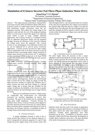
- 1. IJSRD - International Journal for Scientific Research & Development| Vol. 3, Issue 10, 2015 | ISSN (online): 2321-0613 All rights reserved by www.ijsrd.com 267 Simulation of Z-Source Inverter Fed Three Phase Induction Motor Drive Suneel kirar1 C.S. Sharma2 1 PG Scholar 2 Associate Professor 1,2 Department of Electrical Engineering 1,2 Samrat Ashok Technological Institute Vidisha, (M.P.) India Abstract— This paper presents performance characteristics of Z-source inverter (ZSI) fed Induction Motor (IM) drives. Z-Source inverter is a single stage converter which performs both buck-boost energy conversions using the LC impedance network. This reduces the voltage range of the capacitors used and also the cost of the proposed topology which is in turn used to control the speed of an induction motor which is used in many valuable industrial applications. The Z Source inverter is a combined inverter with an additional buck-boost feature and the proposed topology increases the efficiency of the circuit by reducing the voltage stress across the capacitors. The z-source inverter is very advantageous over traditional inverters and we can be employed all ac and dc power conversion applications. Z-source inverter can boost dc input voltage with no requirement of dc to dc boost converter or step up transformer hence overcoming output voltage limitation of voltage source inverter as well as lower cost. A comparison among conventional PWM inverter dc to dc boost PWM inverter and control circuit cost which are the main a power electronics system. Key words: Converter, current-source inverter, inverter, voltage-source inverter, Z-Source inverter, Three phase induction motor. I. INTRODUCTION Z-source inverter can boost dc input voltage with no requirement of dc-dc boost converter or step up transformer, hence overcoming output voltage limitation of traditional voltage source inverter as well as lower its cost. The Z- source inverter advantageously utilizes the shoot-through states to boost the dc bus voltage by gating on both the upper and lower switches of a phase leg. Therefore, the Z- source inverter can buck and boost voltage to a desired output voltage that is greater than the available dc bus voltage. In addition, the reliability of the inverter is greatly improved because the shoot-through can no longer destroy the circuit. There are two traditional converters: voltage-source (or voltage-fed) and current-source (or current-fed) converters (or inverters depending on power flow directions). The gain of the inverter can be controlled by using pulse width modulation. Z-Source Inverter for induction motor drives. Z-Source Inverter can be applied to the entire spectrum of power conversion. It is used as Boost- Buck conversion where a capacitor and inductor are used. In this thesis, the Z-Source Inverter is considered in place of Voltage Source Inverter and Current Source Inverter. II. Z SOURCE INVERTER A unique impedance network is used in the z- source inverter that consists of two identical inductors L1 and L2 alongwith two identical capacitors C1 and C2 that couples the power supply circuit to the inverter circuit. The shoot through period i.e., the time period when two switches of the same leg are gated allows the voltage to be boosted to the required value when the input dc voltage is not upto the required level. Else otherwise, the shoot through state is not used thus enabling the ZSI to operate as both a buck-boost inverter unlike the traditional voltage source and the current source inverters. Fig. 1: Equivalent circuit of z-source inverter The above figure shows the presence of the z source impedance network preceding the inverter main circuit. The diode is used to prevent the reverse flow of current in the circuit. Fig 2a&2b represent the equivalent circuit of the Z source network in shoot through and non shoot through states respectively. The energy is stored in the inductors in the shoot through state when both the switches on the same leg of the inverter are gated. This energy is then transferred in addition to the supply voltage to the load side when normal gating of the inverter switches occur. Fig. 2: Equivalent circuit of Z source inverter in (a).shoot through state and (b) non shoot through state. III. INDUCTION MOTOR Induction motor has been used in the mainly in application requiring a constant speed because conventional method of their speed control has either been expensive or highly inefficient. Variable speed applications have been dominated by dc drive. Availability of thyristors, power transistors, IGBT and GTO has allowed the development of variable speed 1induction motor drive. The main drawback of dc motor is the presence of commutated and brushes
- 2. Simulation of Z-Source Inverter Fed Three Phase Induction Motor Drive (IJSRD/Vol. 3/Issue 10/2015/064) All rights reserved by www.ijsrd.com 268 Three phase induction motors are the most widely used in various industrial applications because of the following properties – 1) Self starting property 2) Elimination of a starting device 3) Robust construction 4) Higher power factor and good speed regulation. IV. CIRCUIT AND SIMULATION Fig: 3- Simulation result of rectification. Simulation is performed using MATLAB/SIMULINK software. Simulink liabrary files include inbuilt models of many electrical and electronic components and devices such as diodes, MOSFETS, capacitors, inductors, motors, power supplies. The circuit components are connected as per design without error, parameters of all components are configuration as per requirement and simulation is perform. Maximum constant boost control with third harmonic injection method is used PWM generation and simulation. The complete simulation diagram is shown in the figure 5.2. The component values of z-source inverter depend on switching frequency only. For this circuit L1 = L2 = 8.5mH and C1 = C2 = 250uF. The purpose of the system is to produce 230V line to line voltage. For PWM generation the carrier frequency is set to 10 kHz and modulation reference signal frequency is set to 50Hz. Fig. 4: Simulation of z-source inverter fed three phase induction motor
- 3. Simulation of Z-Source Inverter Fed Three Phase Induction Motor Drive (IJSRD/Vol. 3/Issue 10/2015/064) All rights reserved by www.ijsrd.com 269 Fig. 5: Input Waveform of Applied Ac Voltage. Fig. 6: Output wave form of DC voltage. Fig. 7: Waveform of stator current.
- 4. Simulation of Z-Source Inverter Fed Three Phase Induction Motor Drive (IJSRD/Vol. 3/Issue 10/2015/064) All rights reserved by www.ijsrd.com 270 Fig. 8: Load voltage waveform Fig. 9: Rotor speed in rpm of induction motor. V. CONCLUSION This paper has proposed a Z – source inverter based induction motor drive. This drive system has the advantages of both PMBDCM and Z-source inverter. The system configuration, operation principle and control method have been analyzed in detail. And based on the equivalent circuits, the mathematical model has been established by state-space averaging method. Simulation results have validated the preferred features as well as the possibility of the proposed drive system. Additionally, the shortcoming of switching loss has been discussed, and a possible improvement method has been presented. A PWM control method was carried out in this paper for z-source Inverter fed induction motor drive. The output voltage obtained from ZSI is not limited and can be boosted beyond the limit imposed by conventional VSI REFERENCES [1] Fang Zheng Peng, “Z- Source Inverter”, IEEE Transaction on Industry Applications. 29. 2003, 2. Wuhan,China. [2] G.Pandian and S. Rama Reddy, “Embedded Controlled Z Source Inverter Fed Induction Motor Drive” IEEE transaction on industrial application, vol.32, no.2, May/June 2010. [3] K. Srinivasan and Dr. S. S. Das, “Performance Analysis of a Reduced Switch Z-Source Inverter fed IM Drives”, Journal of Power Electronics, Vol. 12, No. 2, May/June 2010. [4] K.Niraimathy, S.Krithiga, “A New Adjustable-Speed Drives (ASD) System Based On High-Performance Z- Source Inverter”, 978-1-61284-379- 7/11/2011 IEEE, 2011 1st International Conference on Electrical Energy Systems. [5] Muhammad H. Rashid, “Power Electronics”, Second Edition, Pearson Education. [6] Miaosen Shen, Jin Wang, Alan Joseph, Fang Zheng Peng, Leon M. Tolbert, and Donald J. adams, “Constant Boost Control of the Z-Source Inverter to Minimize Current Ripple and Voltage Stress”, IEEE Transactions on industry application vol. 42, no. 3, May/June 2006. [7] Omar Ellabban, Joeri Van Mierlo and Philippe Lataire, “Comparison between Different PWM Control Methods for Different Z-Source Inverter Topologies” IEEE Transactions on industry application, May/June 2010. [8] S. Rajakaruna, Member, IEEE and Y. R. L. Jayawickrama, “Designing Impedance Network of Z- Source Inverters” IEEE Transactions on industry application. [9] Muhammad H. Rashid, “Power Electronics”, Third Edition, Pearson Education. [10]Dr. P.S. Bimbhra, “Power Electronics”, Fifth Edition, Khanna Publishers. [11]Gopal K. dubey, “Fundamentals Electrical Drives”,Second Edition, Narosa Publishers.