SlideShare a Scribd company logo
1 of 91
Download to read offline
SEISMIC DESIGN GUIDE
FOR LOW-RISE CONFINED MASONRY BUILDINGS
Prepared by
Roberto Meli, Mexico (Co-Chair)
Svetlana Brzev, Canada (Co-Chair)
Maximiliano Astroza, Chile
Teddy Boen, Indonesia
Francisco Crisafulli, Argentina
Junwu Dai, China
Mohammed Farsi, Algeria
Tim Hart, USA
Ahmed Mebarki, France
A.S. Moghadam, Iran
Daniel Quiun, Peru
Miha Tomazevic, Slovenia
Luis Yamin, Colombia
August 2011
Confined Masonry Network
A Project of the World Housing Encyclopedia, EERI & IAEE
With funding support from Risk Management Solutions
© 2011 Earthquake Engineering Research Institute, Oakland, California 94612-1934.
All rights reserved. No part of this book may be reproduced in any form or by any
means without the prior written permission of the publisher, Earthquake Engineering
Research Institute, 499 14th St., Suite 320, Oakland, CA 94612-1934. Telephone:
510/451-0905, Fax: 510/451-5411, E-mail: eeri@eeri.org, Web site: www.eeri.org
This tutorial is published by the Earthquake Engineering Research Institute, a nonprofit
corporation. The objective of the Earthquake Engineering Research Institute is to
reduce earthquake risk by advancing the science and practice of earthquake
engineering by improving understanding of the impact of earthquakes on the physical,
social, economic, political, and cultural environment, and by advocating comprehensive
and realistic measures for reducing the harmful effects of earthquakes.
Production of this tutorial has been supported in part by a generous contribution from
Risk Management Solutions, Inc., Newark, California.
This tutorial was written and reviewed by volunteers, all of whom participate in EERI
and IAEE’s World Housing Encyclopedia project. Any opinions, findings, conclusions, or
recommendations expressed herein are the authors’ and do not necessarily reflect the
views of their organizations.
ISBN: 978-1-932884-56-2
EERI Publication Number WHE-2011-02
Seismic Design Guide for Low-Rise Confined Masonry Buildings
2
Acknowledgments
These guidelines were prepared by a committee of international experts, led by Roberto Meli of
Mexico and Svetlana Brzev of Canada. Other committee members were: Maximiliano Astroza,
Chile; Teddy Boen, Indonesia; Francisco Crisafulli, Argentina; Junwu Dai, China; Mohammed Farsi,
Algeria; Tim Hart, USA; Ahmed Mebarki, France; A.S. Moghadam, Iran; Daniel Quiun, Peru; Miha
Tomazevic, Slovenia; and Luis Yamin, Colombia.
Particular thanks are due to Leonardo Flores and Miguel Angel Pacheco, research engineers at the
National Centre for Disaster Prevention, Mexico City. They were responsible for compiling many of
the codes that were reviewed as part of this project, conducting some of the analyses and
preparing the drawings and figures.
The authors gratefully acknowledge comments and suggestions made by Sergio Alcocer (Mexico),
Richard Klingner (USA), and Durgesh Rai (India), who were external reviewers for this document.
Detailed review comments by Andrew Charleson, Editor-in-Chief of the World Housing
Encyclopedia, contributed to the quality of the document and are gratefully appreciated. The
authors would also like to thank Bill McEwen of the Masonry Institute of British Columbia,
Vancouver, Canada, Arturo Tena Colunga, and Greg Hale, SWBR, Rochester, NY, USA who
reviewed this document and gave very useful comments.
The authors would also like to acknowledge the financial support of Risk Management Solutions in
the early stages of this project, and in particular the enthusiastic support received from Sahar
Safaie. The authors also acknowledge the ongoing support of the Earthquake Engineering
Research Institute and the staff member Marjorie Greene. The authors appreciate assistance by
Michael Germeraad, EERI Graduate Intern, in the editing stage of this publication.
Special thanks are due the National Information Centre of Earthquake Engineering at the Indian
Institute of Technology, Kanpur, India, for allowing us to incorporate part of one of their publications
on confined masonry, authored by co-chair Svetlana Brzev.
If you have comments on this document, please forward them to Marjorie Greene at
mgreene@eeri.org.
Seismic Design Guide for Low-Rise Confined Masonry Buildings
3
Table of Contents
1 INTRODUCTION.........................................................................................................................5
1.1 Scope and Objectives ...........................................................................................................................5
1.2 What is Confined Masonry Construction?..........................................................................................6
1.2.1 Key Components of a Confined Masonry Building..........................................................................6
1.2.2 Confined Masonry and Similar Building Technologies....................................................................7
1.3 Seismic Response of Confined Masonry Buildings ....................................................................... 10
1.3.1 Performance of Confined Masonry Buildings in Past Earthquakes.............................................. 10
1.3.2 General System Behavior............................................................................................................. 11
1.3.3 Seismic Failure Mechanisms........................................................................................................ 17
1.3.4 Seismic Response of Multi-story Confined Masonry Buildings.................................................... 21
1.3.5 Design and Construction Deficiencies Observed in Recent Earthquakes ................................... 24
2 GENERAL REQUIREMENTS...................................................................................................28
2.1 Design and Performance Objectives................................................................................................ 28
2.2 Seismic Hazard................................................................................................................................... 28
2.3 General Planning and Design Aspects ............................................................................................ 29
2.4 Materials .............................................................................................................................................. 32
2.4.1 Units.............................................................................................................................................. 32
2.4.2 Mortar ........................................................................................................................................... 34
2.4.3 Concrete ....................................................................................................................................... 34
2.4.4 Reinforcing Steel .......................................................................................................................... 34
2.4.5 Masonry........................................................................................................................................ 35
2.4.6 Testing of Masonry Materials ....................................................................................................... 36
3 GUIDELINES FOR NON-ENGINEERED CONFINED MASONRY BUILDINGS......................37
3.1 Building Components ........................................................................................................................ 37
3.1.1 Masonry Walls .............................................................................................................................. 37
3.1.2 Confining Elements (Tie-columns and Tie-beams) ...................................................................... 44
3.1.3 Additional Requirements for Buildings with Flexible Diaphragms................................................ 49
3.2 Construction Quality.......................................................................................................................... 51
CONCLUDING REMARKS..............................................................................................................52
REFERENCES.................................................................................................................................53
Seismic Design Guide for Low-Rise Confined Masonry Buildings
4
APPENDICES
A Simplified Method for Wall Density Calculation in Low-Rise Buildings 56
B Guidelines for Inspection of Confined Masonry Construction 70
C Summary of Seismic Design Provisions for Confined Masonry Buildings from Relevant
International Codes and Standards 78
Seismic Design Guide for Low-Rise Confined Masonry Buildings
5
1 Introduction
1.1 Scope and Objectives
The purpose of this document is to:
• Explain the mechanism of seismic response of confined masonry buildings for in- and out-of-
plane seismic effects and other relevant seismic response issues,
• Recommend prescriptive design provisions for low-rise buildings related to the wall layout and
density, and prescribe minimum size requirements for structural components of confined
masonry buildings (tie-columns, tie-beams, walls), reinforcement size and detailing, and
• Provide a summary of the seismic design provisions for confined masonry buildings from
relevant international codes.
This document is divided into three chapters. Chapter 1 provides an overview of confined masonry
construction and its components. It discusses the seismic performance of confined masonry
buildings in past earthquakes, and is based largely on the publication Earthquake-Resistant
Confined Masonry Construction (Brzev, 2008). Chapter 2 presents general requirements related to
confined masonry construction. Chapter 3 outlines a guideline for low-rise non-engineered confined
masonry buildings (up to two stories high). These buildings could be constructed without
engineered design performed by qualified engineers or architects, and thus no design calculations
or procedures are included. Many single-family dwellings are built in this manner.
Although this guide is focused on low-rise confined masonry buildings, medium-rise engineered
buildings of this type (up to five stories high) can be designed and built following the
recommendations of this document and other relevant international codes and standards. However,
note that additional analysis and design procedures and requirements for engineered confined
masonry buildings are outside the scope of this document.
It is expected that this guide will be a useful resource for design engineers and architects,
academics, code development organizations and non-governmental organizations in countries in
which design codes and standards do not contain seismic design provisions for confined masonry
construction. This document may also be a useful reference for design engineers and other
professionals in the countries where code design provisions for confined masonry construction are
currently in place.
This document was developed by a group of international experts in earthquake engineering and
confined masonry construction. The recommendations are based on design and construction
experience and research studies from countries and regions where confined masonry construction
has been practiced for many decades, including Mexico, Peru, Chile, Argentina, Iran, Indonesia,
China, Algeria and Slovenia. References to relevant provisions of various international standards
and codes have been made in the document.
Seismic Design Guide for Low-Rise Confined Masonry Buildings
6
1.2 What is Confined Masonry Construction?
1.2.1 Key Components of a Confined Masonry Building
Confined masonry construction consists of masonry walls and horizontal and vertical reinforced
concrete (RC) confining elements built on all four sides of a masonry wall panel, as shown in Figure
1. Vertical elements, called tie-columns, resemble columns in RC frame construction except that
they tend to be of far smaller cross-sectional dimensions. Most importantly, these RC members are
built after the masonry wall has been completed. Horizontal elements, called tie-beams, resemble
beams in RC frame construction but they are not intended to function as conventional beams since
confined masonry walls are load-bearing. Alternative terms, horizontal ties and vertical ties, are
sometimes used instead of tie-beams and tie-columns.
The key features of structural components of a confined masonry building are discussed below:
• Masonry walls transmit the gravity load from the slab(s) above down to the foundation (along
with the RC tie-columns). This document addresses confined masonry construction consisting
of masonry walls made of solid clay bricks, hollow clay tiles, or concrete blocks. The walls act
as bracing panels, which resist horizontal earthquake forces acting in-plane. The walls must be
confined by RC tie-beams and tie-columns and should not be penetrated by significant
openings to ensure satisfactory earthquake performance.
• Confining elements (RC tie-columns and RC tie-beams) are effective in improving stability and
integrity of masonry walls for in-plane and out-of-plane earthquake effects. These elements
prevent brittle seismic response of masonry walls and protect them from complete
disintegration even in major earthquakes. Confining elements, particularly tie-columns,
contribute to the overall building stability for gravity loads.
• Floor and roof slabs transmit both gravity and lateral loads to the walls. In an earthquake, floor
and roof slabs behave like horizontal beams and are called diaphragms. The roof slabs are
typically made of reinforced concrete (see Figure 1 a), but light-weight roofs made of timber or
light gage steel as shown in Figure 1 b are also used.
• Plinth band transmits the load from the walls down to the foundation. It also protects the ground
floor walls from excessive settlement in soft soil conditions and the moisture penetration into the
building.
• Foundation transmits the loads from the structure to the ground.
It should be noted that the term “confined masonry” is also used in a general sense for different
forms of masonry construction reinforced with additional steel, timber, or concrete elements,
however those construction practices are outside the scope of this document.
Seismic Design Guide for Low-Rise Confined Masonry Buildings
7
a) b)
Figure 1. A typical confined masonry building: a) flat RC roof (Brzev, 2008), and b) pitched timber
roof (Boen, 2009).
1.2.2 Confined Masonry and Similar Building Technologies
Confined masonry building technology is somewhat similar to both reinforced masonry and
reinforced concrete frame construction with infill walls. It should be noted, however, that differences
between these building technologies are significant in terms of construction sequence, complexity,
and seismic performance. Since features of confined masonry construction practice are not well
known on a global scale, a comparison of these building technologies is presented next.
Reinforced Masonry and Confined Masonry: A Comparison
In reinforced masonry, vertical and horizontal reinforcing bars are provided to enhance the strength
and ductility (deformability) of masonry walls. Masonry units are usually hollow and made either of
concrete or clay. Vertical reinforcing bars are placed in the hollow cores, which are subsequently
grouted with a cement-based grout to anchor the reinforcement and protect it from corrosion.
Vertical reinforcement is placed at the wall corners and intersections, around the openings, and at
additional locations depending on expected seismic loads. Horizontal reinforcement is provided in
the form of ladder-shaped wire reinforcement placed in horizontal joints, or deformed reinforcing
bars placed in bond beams, typically located at floor and/or lintel levels.
In confined masonry, the reinforcement is concentrated in vertical and horizontal RC confining
elements whereas the masonry walls are usually free of reinforcement. Figure 2 illustrates the
difference between reinforced and confined masonry construction. Advanced construction skills and
inspection at different stages of construction are necessary to ensure quality of reinforced masonry.
For example, vertical wall reinforcement placed in the hollow cores in masonry blocks must be
continuous from the foundation to the roof level, and must match dowels (vertical bars) extended
from the foundation. Subsequently, hollow cores (cells) in reinforced masonry blocks need to be
filled with cement-based grout with specific mix proportions for placing it into relatively small-sized
cores. Horizontal reinforcement is placed into bond beam blocks which also need to be grouted.
Specialized equipment is used for pumping grout into masonry. Confined masonry is a simpler and
Seismic Design Guide for Low-Rise Confined Masonry Buildings
8
more forgiving building technology, since the use of steel reinforcement and concrete is limited to
confining elements (vertical tie-columns and horizontal tie-beams). The quality of RC confining
elements in terms of reinforcement detailing and concrete construction can be verified with more
confidence compared to similar components of reinforced masonry construction (e.g. placement of
reinforcement and grout in hollow block cores).
a) b)
Figure 2. Masonry building technologies: a) confined masonry construction in Chile (S. Brzev), and
b) reinforced masonry construction in Canada (B. McEwen).
RC Frames with Masonry Infill Walls and Confined Masonry: A Comparison
The appearance of a finished confined masonry construction and a RC frame infilled with masonry
wall panels may look alike, however these two construction systems are substantially different, as
illustrated in Figure 3 (note that Figure 3a shows features of RC frames with infills, while Figure 3b
shows confined masonry construction). The main differences are related to i) the construction
sequence, and ii) the manner in which these structures resist gravity and lateral loads.
The differences related to the construction sequence are as follows:
• In confined masonry construction, masonry walls are constructed first, one story at a time,
followed by the cast in-place RC tie-columns. Finally, RC tie-beams are constructed on top
of the walls, simultaneously with the floor/roof slab construction.
• In RC frame construction infilled with masonry wall panels, the frame is constructed first,
followed by the masonry wall construction.
It is important to explain why seismic response of confined masonry buildings is different from RC
frames with masonry infills. The main reasons are summarized below:
• Due to smaller cross-sectional dimensions, RC tie-columns in confined masonry
construction are slender and cannot provide an effective frame action. Tie-beam-to-tie-
column connections are pinned (similar to post-and-beam timber construction), as opposed
to the moment connections in RC frames. Beams and columns in RC frame construction
are much larger in size, and they have significantly larger stiffness relative to the infill.
• Tie-columns are cast against a rough (toothed and/or doweled) surface, and thus are
integrated into the masonry wall in confined masonry construction. On the contrary, infill
walls are usually not integrated into a RC frame - there is no toothing and there are rarely
any dowels.
• Gravity loads in confined masonry construction are mostly supported by the masonry
walls, while infills in RC frames bear mostly self-weight. Due to the significant frame
Seismic Design Guide for Low-Rise Confined Masonry Buildings
9
stiffness, only a small portion of the floor load is transferred to the infills. Also, in infill
construction it is not uncommon to have gaps between the masonry blocks and the
concrete beams. These gaps are created when the blocks do not fit tightly to the underside
of the beams. These gaps allow the beams to deflect without transferring the gravity loads
to the wall below.
• When subjected to lateral seismic loads, walls in confined masonry buildings act as shear
walls, similar to unreinforced or reinforced masonry walls or RC shear walls. On the other
hand, infill wall panels in RC frame buildings do not act as shear walls - they act as diagonal
struts. The gaps, due to a relative lack of bond between the masonry infill and the RC
frame, drastically minimize the capability of infill walls from resisting the lateral forces in a
seismic event, as illustrated in Figure 3 a. Note that these gaps may already exist before an
earthquake due to construction tolerances.
1 2
1 2
Infill wall
Load bearing wall
column
tie-column
beam
tie-beam
Infill wall Load bearing wall
a) b)
Figure 3. A comparison of RC frames with masonry infills (a), and confined masonry construction
(b): construction sequence (top); size of confining elements (middle), and the seismic response
(bottom).
Detailing of reinforcement in RC confining elements is relatively simple, however the placement of
concrete may be challenging due to smaller dimensions of these elements compared to traditional
RC construction. It is easier to perform an inspection of concrete construction in a confined
masonry building compared to an RC frame building or a reinforced block masonry building.
Reasons for this include the fact that the reinforcing in a confined masonry construction is much
simpler, lower strength concrete can often be used, and the hollow cores within the masonry blocks
do not need to be fully aligned. Due to a lower consumption of steel and cement, construction of a
confined masonry building is expected to be more economical compared to an otherwise similar RC
Seismic Design Guide for Low-Rise Confined Masonry Buildings
10
frame building with masonry infills (particularly in developing countries where labor is relatively
inexpensive).
1.3 Seismic Response of Confined Masonry Buildings
1.3.1 Performance of Confined Masonry Buildings in Past Earthquakes
Confined masonry construction has evolved through an informal process based on its satisfactory
performance in past earthquakes. The first reported use of confined masonry construction was in
the reconstruction of buildings destroyed by the 1908 Messina, Italy earthquake (M 7.2), which
killed over 70,000 people. Over the last 30 years, confined masonry construction has been
practiced in Mediterranean Europe (Italy, Slovenia, Serbia), Latin America (Mexico, Chile, Peru,
Colombia, Argentina, and other countries), the Middle East (Iran, Algeria, Morocco), South Asia
(Indonesia), and the Far East (China). It is important to note that confined masonry construction is
widely used in countries and regions of extremely high seismic hazard. Several examples of
confined masonry construction around the world, from Argentina, Chile, Iran, Peru, Serbia and
Slovenia, are featured in the World Housing Encyclopedia (EERI/IAEE, 2000).
Well built confined masonry buildings were able to survive the effects of major earthquakes without
collapse and in most cases without significant damage. Confined masonry tends to be quite
forgiving of minor design and construction flaws, as well as material deficiencies provided that the
buildings have regular floor plan and sufficient wall density. Poor seismic performance has been
noted only where gross construction errors, design flaws, or material deficiencies have been
introduced in the building design and construction process. Poor performance is usually associated
with insufficient amount of confined masonry walls in one or both plan directions, inadequate size of
the tie-columns, deficiencies in tie-column reinforcement in terms of amount and detailing,
discontinuous tie-beams, inadequate diaphragm connections, and inappropriate structural
configuration.
The earliest reports describing the earthquake performance of confined masonry buildings date
back to the 1939 Chile earthquake (M 7.8). In Chillán, where Modified Mercalli Intensity (MMI) of IX
was reported, over 50% of all inspected confined masonry buildings survived the earthquake
without any damage, whereas around 60% of unreinforced masonry buildings either partially or
entirely collapsed, resulting in a death toll of 30,000. Following the 1939 earthquake, confined
masonry was exposed to several significant earthquakes in Chile, including the 1985 Llolleo
earthquake (M 7.8) and, more recently, the February 27, 2010 Maule earthquake (M 8.8). Low-rise
confined masonry buildings performed very well in the Maule earthquake. Figure 4 a shows a two-
story confined masonry house in Curepto which remained virtually undamaged, while the adjacent
adobe house has collapsed (see Astroza et al. (2010) and Brzev et al. (2010) for more details on
performance of confined masonry buildings in the 2010 Chile earthquake).
A very similar observation was made after the 2007 Pisco, Peru earthquake (M 8.0), where
confined masonry buildings performed very well compared to other types of masonry buildings
which were badly damaged or collapsed. Figure 4 b shows a four-story confined masonry building
in Ica, Peru which remained virtually undamaged in the earthquake. Seismic performance of
confined masonry buildings in other countries will be illustrated in the following sections.
Earthquake-induced life loss in confined masonry buildings has been insignificant in countries and
regions where this technology has been practiced. However, a few medium-rise confined masonry
buildings collapsed in recent earthquakes, e.g. the 2010 Maule, Chile earthquake and the 2007
Pisco, Peru earthquake (see Section 1.3.4 for a detailed discussion).
Seismic Design Guide for Low-Rise Confined Masonry Buildings
11
Since confined masonry buildings performed well in past earthquakes, resources related to seismic
repair and retrofit of these buildings are limited. The reader is referred to a publication developed
after the 2009 Pisco, Peru earthquake (PNUD, 2009), and another one prepared after the 2002
Colima, Mexico earthquake (EERI, 2006).
a) b)
Figure 4. Performance of confined masonry buildings in recent significant earthquakes: a) the 2010
Maule, Chile earthquake (M.O. Moroni Yadlin), and b) the 2007 Pisco, Peru earthquake (D. Quiun).
1.3.2 General System Behavior
1.3.2.1 How Seismic Forces are Resisted by a Confined Masonry Wall Panel
Seismic behavior of a confined masonry wall panel can be explained by composite (monolithic)
action of a masonry wall and adjacent RC confining elements. This composite action exists due to
the toothing between the walls and the tie-columns - that is one of the key features of confined
masonry construction. In the absence of toothing, composite action can be achieved by means of
horizontal reinforcement (dowels). Figure 5 shows a two-bay confined masonry specimen subjected
to reversed cyclic lateral loading simulating earthquake effects (Pérez-Gavilán, 2009). The
specimen demonstrated a typical damage pattern in the form of diagonal shear cracks. The failure
took place in the form of a single diagonal crack which propagated through the walls and the tie-
columns. This mechanism can be expected to occur in buildings with small RC tie-column sizes,
where tie-column depth does not exceed 1.5 times the wall thickness.
Figure 5. Failure of a two-bay confined masonry wall (Pérez-Gavilán, 2009).
Seismic Design Guide for Low-Rise Confined Masonry Buildings
12
When the tie-columns and tie-beams have larger sections (depths in excess of two times the wall
thickness), relative stiffness of these elements compared to the walls is significant. As a result,
behavior of a confined masonry wall panel is similar to an RC frame with masonry infill wall panel. A
confined masonry wall panel can be modeled using the "strut and tie" model, where a vertical crack
(separation) develops between the wall and the adjoining tie-columns. At the certain load level, the
wall will start to act like a diagonal strut, while the adjacent columns act in tension and/or
compression, depending on the direction of lateral earthquake forces. The difference between the
two cases is clearly shown in the experimental study by San Bartolomé et al. (2010), where the
confined masonry wall specimens had two different tie-column widths (200 and 400 mm). A vertical
separation between the wall and tie-columns occurred in the specimen M2 with 400 mm wide tie-
columns. Failure mechanism of the specimen M1 with 200 mm wide columns was characterized by
composite wall and tie-column action and diagonal cracking, where cracks propagated into the
columns. Damage patterns in the specimens at the final stage of testing are shown in Figure 6.
a)
b)
Figure 6. Seismic behavior of masonry walls confined by RC tie-columns: a) composite wall and tie-
column action (specimen M1 with 200 mm wide tie-columns), and b) vertical separation at the wall-
to-column interface (specimen M2 with 400 mm wide columns) (San Bartolomé et al. 2010).
Shear capacity of a confined masonry wall panel (3) can be determined as the sum of contributions
of the masonry wall (1) and the adjacent RC tie-columns (2), as shown in Figure 7. Note that the
shear capacity of tie-columns can be reached only after the masonry has been severely cracked
and its shear capacity has significantly decreased. As a result, it is recommended to consider only
a partial contribution of tie-columns to the shear capacity of a confined masonry panel. A
conservative estimate can be made by assuming that the tie-columns are integrated with the
masonry wall, thus a cross-sectional area of the confined masonry wall can be calculated by taking
into account the total panel length. This approach is the basis for deriving the minimum required
wall density (see Appendix A of this document).
Seismic Design Guide for Low-Rise Confined Masonry Buildings
13
It can be seen from the diagram in Figure 7 that the stiffness and strength of a confined masonry
panel drop following the onset of diagonal cracking in the wall (point 1). However, the load-resisting
capacity of the panel is maintained until the critical regions of the confining elements experience
significant cracking (point 2). This shows that a significant lateral deformation and ductility can be
attained before the failure of a properly designed and constructed confined masonry panel (point 3).
Displacement
Shearforce
1 2 3
1
2
3
P P P
V
Vm
Vm
V 'm
Σ Vc
Vc
Vc
V 'm
Figure 7. Mechanism of shear resistance for a confined masonry wall panel: 1) diagonal cracking in
the masonry wall; 2) diagonal cracks have propagated from the wall into the tie-columns, and 3)
shear failure of the RC tie-columns and the confined masonry wall panel.
Critical regions in a confined masonry structure are end zones of tie-columns (top and bottom
region at each floor level), as shown in Figure 8 a. An example of a confined masonry wall panel
which experienced significant damage in the RC tie-columns in the 2010 Chile earthquake is shown
in Figure 8 b.
In most cases, confined masonry panels demonstrate a shear-dominant seismic response.
Longitudinal reinforcement in the RC tie-columns provides an adequate flexural resistance, thus the
flexural failure mechanism does not govern; this is an assumption taken in Appendix A of this
document.
Seismic Design Guide for Low-Rise Confined Masonry Buildings
14
Masonry walls
Critical regions
Diagonal cracking
window
a)
b)
Figure 8. Critical regions in a confined masonry building: a) a general diagram showing critical
regions in the RC tie-columns, and b) tie-column damage observed in the 2010 Chile earthquake
(M. Astroza).
Confined masonry panels are subjected to the effects of axial gravity load (due to self-weight and
tributary floor/roof loads). Figure 9 a illustrates a confined masonry panel which resists the
combined effect of axial load P and bending moment M. The capacity of the composite confined
masonry panel section under the combined effect of axial load and bending moment can be
determined by treating the confined masonry panel similar to a RC shear wall acting in unison with
the adjacent columns. The strain diagram shows that a portion of the panel is in tension, while the
remaining portion is in compression (see Figure 9 b). It is assumed that the masonry and concrete
are not able to resist tension, hence tensile stresses are resisted by the longitudinal reinforcement
in tie-columns. The compression stresses are resisted by concrete, masonry, and longitudinal
reinforcement in tie-columns (see Figure 9 c). The flexural capacity of the panel section is
determined from the sum of moments created by various internal forces around point O (centroid of
the section).
Seismic Design Guide for Low-Rise Confined Masonry Buildings
15
Compression
steel
Tension
steel
Tension
Compression
Compression
masonry
Compression
concrete
h
V
P
M = Vxh
P
a)
b)
c)
M
P
O
Figure 9. A confined masonry wall panel subjected to the combined axial load and bending: a)
panel elevation and a typical cross-section; b) strain distribution, and c) internal force distribution.
1.3.2.2 The Effect of Floor and Roof Systems
The seismic response of a confined masonry building and the internal distribution of earthquake
forces depend on the type of floor and/or roof system. Floor and roof systems are horizontal
elements of the lateral load-resisting system that act as diaphragms. Their primary role is to
transfer earthquake-induced lateral forces in the building to vertical elements (shear walls) that
resist these forces. A diaphragm can be treated as an I-shaped beam laid in the horizontal plane.
The floor or roof functions as the web to resist the shear forces, while the boundary elements (tie-
beams in confined masonry buildings) act as the flanges and resist tension and compression
stresses due to bending moments. The manner in which the total shear force is distributed to the
vertical elements (walls) depends on the wall rigidity relative to the diaphragm rigidity. For design
purposes, diaphragms are usually treated either as flexible or rigid. Timber or light gage steel
diaphragms are generally considered as flexible (unless bracing is provided in the plane of the
diaphragm), while cast in-place concrete or composite masonry and concrete floor systems are
usually considered as rigid diaphragms.
In buildings with flexible diaphragms, the distribution of shear forces to walls is independent of their
relative rigidity. These diaphragms act like a series of simple horizontal beams spanning between
the walls, as shown in Figure 10 a. A flexible diaphragm must have adequate strength to transfer
the shear forces to the walls, but cannot distribute torsional forces to the walls in the direction
perpendicular to the earthquake ground motion. Flexible diaphragms are not common in confined
masonry buildings, with the exception of countries in warm climate regions, e.g. Indonesia, Chile,
etc., where timber trusses have been routinely used for the roof construction. An example of a
confined masonry building with a flexible timber roof diaphragm is shown in Figure 1 b. Seismic
Seismic Design Guide for Low-Rise Confined Masonry Buildings
16
response of confined masonry buildings with flexible diaphragms and the key factors influencing the
response were studied by Hart et al. (2010).
In buildings with rigid diaphragms, shear forces in the walls are in direct proportion to the wall
rigidity (relative to the rigidity of other walls laid in the same direction), as shown in Figure 10 b. In
low-rise buildings, wall rigidity is proportional to its cross-sectional area (A), as indicated in the
figure. (Note that this distribution applies only to low-rise buildings where shear response is
predominant in the walls.) Torsional effects need to be considered, and may increase seismic
forces in some of the walls. Buildings with rigid diaphragms are very common in most countries
where confined masonry has been practiced. Figure 1 a shows RC floor and roof slabs which act
like rigid diaphragms.
W1
W3
W2
W1
W3
W2
B
B
νV = νB
V = νB
ν
V/4
V/2
V/4
A1
V
A
ΣA
1
ΣA = A +A +A1
ν
V/4
V/2
V/4B/2
B/2
W1
W2
W3
W1
W2
W3
Flexible
diaphragm
Rigiddiaphragm
V
A
ΣA
2
V
A
ΣA
3
A2
A3
2 3
V = νB
V
A
ΣA
1
V
A
ΣA
2
V
A
ΣA
3
a) b)
V = νB
Figure 10. Distribution of lateral loads in buildings: a) flexible, and b) rigid diaphragms.
Seismic Design Guide for Low-Rise Confined Masonry Buildings
17
1.3.3 Seismic Failure Mechanisms
1.3.3.1 Introduction
Failure mechanisms in confined masonry wall panels depend on the direction of earthquake
loading. There are two possible scenarios:
a) Earthquake ground shaking in the direction parallel with the longitudinal wall axis, also
known as in-plane seismic loading, or
b) Earthquake ground shaking perpendicular to the longitudinal wall axis, or out-of-plane
seismic loading.
Seismic response of confined masonry structures subjected to in-plane and out-of-plane seismic
loading is discussed in the following sections.
1.3.3.2 In-plane Failure Mechanisms
A confined masonry wall subjected to in-plane lateral earthquake loading develops either a shear or
flexural failure mechanism (Tomazevic and Klemenc, 1997; Tomazevic, 1999; Yoshimura et al.
2004).
Shear failure mechanism is characterized by distributed diagonal cracking in the wall. The damage
is caused either by the bond destruction at the mortar-brick interface (shear-friction mechanism), or
tensile cracking in the masonry units. Initially, a masonry wall panel resists the effects of lateral
earthquake loads while the RC tie-columns do not play a significant role. However, once cracking
takes place, the wall pushes the tie-columns sideways. At that stage, the vertical reinforcement in
the tie-columns resists tension and compression stresses (Tomazevic and Klemenc, 1997).
Damage in the tie-columns at the ultimate load level is concentrated at the top and bottom of the
panel. Shear failure can lead to severe damage in the masonry wall and at the top and bottom of
the tie-columns, as shown in Figure 11. (Note that this mechanism was also discussed in Section
1.3.2.1.)
Figure 11. Shear failure of confined masonry walls (Yoshimura et al., 2004 – left; Aguilar and
Alcocer, 2001 – right).
In-plane shear failure of ground floor confined masonry walls is the most common damage pattern
observed in past earthquakes, e.g. the 1999 Tehuacán and the 2003 Tecomán, Mexico
earthquakes, the 2001 San Salvador, El Salvador earthquake, and the 2010 Maule, Chile
earthquake. Figure 12 a shows damage at the ground floor level of a three-story building in
Cauquenes. The building was constructed in 1993, before the 1997 edition of Chilean code
NCh2123, which contains relevant design restrictions for confined masonry buildings, had been
issued. Figure 12 b shows shear failure of a pier in a confined masonry building due to the 2001 El
Salvador earthquake (note absence of RC tie-columns at openings).
Seismic Design Guide for Low-Rise Confined Masonry Buildings
18
a) b)
Figure 12. In-plane shear failure of poorly confined masonry walls: a) the 2010 Maule, Chile
earthquake (M. Astroza), and b) the 2001 El Salvador earthquake (EERI, 2001).
Flexural failure mechanism due to in-plane lateral loads is characterized by horizontal cracking of
the mortar bed joints located on the tension side of the wall, as shown in Figure 13 (Yoshimura et
al. 2004). Separation of the tie-columns from the wall was observed in some cases when a toothed
wall-to-column connection was absent, and there were no connecting ties between the tie-column
and the wall. Extensive horizontal cracking in tie-columns and shear cracking in the walls can be
observed in Figure 13. Flexural mechanism is not as critical as shear mechanism since it does not
lead to brittle failure, although crushing and disintegration of masonry in the compression toe area
of the wall may take place.
Figure 13. Flexural failure of confined masonry walls (Yoshimura et al., 2004).
RC tie-columns have a critical role in resisting the gravity loads in damaged confined masonry
buildings, and in ensuring their vertical stability (Alcocer, 2006). Due to their high axial stiffness and
tension/compression load resistance, tie-columns resist a major portion of gravity load after the
walls experience severe damage. The failure of a tie-column usually takes place when cracks
propagate from the masonry wall into the tie-column and shear it off. Note that the failure of tie-
column could take place either due to the flexural failure mechanism (shown in Figure 13), or shear
failure mechanism observed in the 2010 Maule, Chile earthquake (see Figure 14 a). It has been
observed that the number of ties at the tie-beam-to-tie-column joint, and the detailing of the
longitudinal reinforcement appear to play a role in the tie-column shear resistance. Buckling of
longitudinal reinforcement was observed when size and/or spacing of ties at the ends of tie-
columns were inadequate (or when the crushing of the masonry units took place), as shown in
Figure 14 b.
Seismic Design Guide for Low-Rise Confined Masonry Buildings
19
a) b)
Figure 14. Failure of RC tie-columns in the 2010 Maule, Chile earthquake: a) shear failure at the
ends of a RC tie-column, and b) buckling of longitudinal reinforcement at the base of a RC tie-
column (S. Brzev).
1.3.3.3 Out-of-plane Seismic Effects on the Walls
Seismic shaking in the direction perpendicular to a masonry wall (also known as out-of-plane
seismic loading) causes bending and shear stresses in the wall. This may result in cracking of the
wall and possible collapse by overturning (toppling). Due to an increase in spectral accelerations up
the building height, the out-of-plane seismic effects are more pronounced at higher floor levels, as
shown in Figure 15 a. In the area affected by the 2010 Maule, Chile earthquake, wall cracking due
to out-of-plane seismic effects was observed at the top floor level, as shown in Figure 15 b (no
damage was observed at lower floors in the same direction). The building had RC floor slabs and
timber truss roof system. (Note that this the same building suffered extensive damage in the
longitudinal direction at the ground floor level, as shown in Figure 12 a.)
The extent of damage and a likelihood of wall collapse depend on the type of roof and floor
diaphragm (rigid or flexible), and how well the wall is attached to its confining elements (if any).
The out-of-plane bending mechanism is critical mainly for buildings with flexible diaphragms, which
are not capable of transmitting the lateral forces to the stiffer walls oriented in the direction of
seismic action. In some cases, this mechanism can also be critical in buildings with rigid
diaphragms due to inertia forces generated by transverse wall vibrations (see Figure 15 a). To
prevent the out-of-plane wall failure, it is important to restrict the maximum spacing of tie-beams
and tie-columns, and ensure toothing/interaction between the walls and the confining elements, as
discussed in this document.
Seismic Design Guide for Low-Rise Confined Masonry Buildings
20
More pronounced
response at higher
levels
a) b)
Figure 15. Out-of-plane seismic response of confined masonry walls: a) a mechanism of seismic
response (Tomazevic, 1999, and b) observed damage at the top floor level of a building after the
2010 Maule, Chile earthquake (M. Astroza).
A possible out-of-plane failure mechanism for walls in buildings with rigid diaphragms is similar to
that characteristic of a two-way slab supported on all sides and subjected to uniformly distributed
loading, as shown in Figure 16 a. This damage pattern was observed at the second floor level of a
three-storey building damaged in the 2010 Maule, Chile earthquake, as shown in Figure 16 b.
Failure mechanisms for out-of-plane wall response are discussed in more detail in Section 3.1.3 of
this document.
L
h
Tie-beam
RC
slab
(rigid diaphragm)
Tie-column
Seismic
force
45°
Transverse wall
a) b)
Figure 16. Out-of-plane seismic effects in confined masonry walls: a) two-way slab mechanism, and
b) evidence from the 2010 Maule, Chile earthquake (S. Brzev).
RC tie-beams have an important role in enhancing the out-of-plane resistance of confined masonry
walls in buildings with flexible diaphragms. These beams need to have adequate size and
reinforcement (in terms of amount and detailing), as discussed in Section 3.1.3. Failure of a free-
standing confined masonry fence in Santa Cruz due to the 2010 Maule, Chile earthquake is a good
example of the out-of-plane wall collapse due to inadequate size of RC tie-beams and inadequate
lap splice length, as shown in Figure 17.
Seismic Design Guide for Low-Rise Confined Masonry Buildings
21
a) b)
Figure 17. Collapse of a confined masonry fence in the 2010 Maule, Chile earthquake due to out-
of-plane seismic effects: a) collapsed fence showing the RC tie-beam failure, and b) detail of RC
tie-beam showing excessively short lap splice length in the longitudinal reinforcement (M. Astroza).
The out-of-plane failure of confined masonry walls has also been observed in buildings with flexible
roof/floor diaphragms which are common in Indonesia.
1.3.4 Seismic Response of Multi-story Confined Masonry Buildings
Earthquake-induced lateral forces in multi-story confined masonry buildings, peak at the ground
floor level and may cause significant shear cracking. Under severe earthquake ground shaking, the
collapse of a confined masonry building may take place at the first story level, as shown in Figure
18. Note that this mechanism is different from the soft-story collapse mechanism which is found in
RC frames with masonry infill walls. In a confined masonry building the stiffness is initially equal at
all floor levels, however the collapse occurs at the first story level due to high seismic loads, which
cause extensive masonry cracking and a resulting decrease in the lateral stiffness. This behavior
was confirmed by experimental studies (Ruiz and Alcocer, 1998; Alcocer et al., 2004, 2004a).
Figure 18. Collapse mechanism for multi-story confined masonry buildings (Alcocer et al., 2004).
In the area affected by the February 2010 Maule, Chile earthquake (M 8.8), a few multi-story
confined masonry buildings experienced significant damage at the ground floor level. Two three-
story buildings collapsed at the first story level, killing ten people in total. One of the collapsed
Seismic Design Guide for Low-Rise Confined Masonry Buildings
22
buildings was located in Santa Cruz, where the maximum observed seismic intensity on the MSK
scale was 7.5; note that the maximum MSK intensity of 9.5 was reported in the earthquake-affected
area (Astroza et al., 2010). The building was a part of the complex consisting of 32 identical
buildings (two rows of 16), as shown in Figure 19 a. Several factors influenced seismic
performance of this building and likely led to its collapse. The building was characterized by
inadequate wall density (less than 1 % calculated on a floor basis), which is significantly less than
the values recommended in this document. The absence of confining elements around openings
resulted in insufficient number of confined wall panels which contribute to lateral load resistance. In
addition, poor quality of construction was observed in a few other buildings within the same
complex -- this resulted in inadequate shear strength of masonry walls. Exterior masonry walls
were built using hollow concrete blocks, while the interior walls were built using hand-made solid
clay bricks. Wall thickness was 150 mm and the RC tie-columns were of square shape with 150
mm cross-sectional dimension. The collapsed building lost its ground floor, as shown in Figure 19
b.
a) b)
Figure 19. Collapse of a three-story confined masonry building in Santa Cruz, Chile due to the
February 2010 Maule earthquake: a) building complex, and b) a building that experienced collapse
at the ground floor level (S. Brzev).
The other collapsed building was located in Constitución, which was affected both by the
earthquake and the subsequent tsunami; note that the maximum observed seismic intensity on the
MSK scale was 9.0 (significantly higher than Santa Cruz) (Astroza et al., 2010). The collapsed
building was a part of a complex of three buildings (A, B, and C) built atop a hill in the proximity of a
steep slope, as shown in Figure 20 a. Building C located closest to the slope (5 m distance on the
west side) collapsed, while buildings A and B suffered damage. The collapsed building C lost its
bottom floor and moved by approximately 1.5 m in the north direction (towards the slope), as shown
in Figure 20 b. Note that building B (located closer to building C) experienced more extensive
damage than building A. The damage in all buildings was more pronounced in the north-south
direction (transverse direction of the building plan). The walls were constructed using hollow clay
blocks, and the thickness was 140 mm. RC tie-columns had different cross-sectional dimensions
depending on the location; the depth was in the range from 140 to 200 mm, and width was equal to
the wall thickness. In addition, a few wide RC columns were placed instead of tie-columns at some
locations and were continuous up the building height -- this practice is followed in medium-rise
confined masonry construction in Chile. Cross-sectional depth of these wide columns varied from
700 to 900 mm and the width was 140 mm (equal to the wall thickness). The columns were
reinforced with vertical and horizontal reinforcement, similar to RC shear walls but without seismic
detailing.
Seismic Design Guide for Low-Rise Confined Masonry Buildings
23
It is believed that the building location and geotechnical effects were the key factors contributing to
the collapse. In addition, a relatively low wall density in the north-south direction (less than 1 %
calculated on a floor basis) and a few deficiencies in the detailing of RC confining elements, were
also observed.
a) b)
Figure 20. Collapse of a three-story confined masonry building in Constitución, Chile due to the
February 2010 Maule earthquake: a) an aerial view of buildings A, B and C (note a steep slope on
the north-west side shown with a solid line), and b) building C (located closest to the slope) lost the
ground floor and moved by approximately 1.5 m away from the plinth towards north (S. Brzev).
Collapse of a four-story confined masonry building was also reported in the 2007 Pisco, Peru
earthquake (M 8.0) (San Bartolomé and Quiun, 2008). The interior walls in the transverse direction
were discontinued at the ground floor level to provide parking space, as shown in Figure 21. The
building collapsed at the ground floor level due to torsional effects.
Figure 21. Collapse of a four-story confined masonry building in the 2007 Pisco, Peru earthquake
(San Bartolomé and Quiun, 2008).
After the 2003 Tecomán (Colima), Mexico earthquake (M 7.8), a three-story confined masonry
apartment building in Colima experienced significant damage at the ground floor level (EERI,
2006). Similar observations related to seismic performance of multi-story confined masonry
buildings were made after the 2008 Wenchuan, China earthquake (M 7.9).
Seismic Design Guide for Low-Rise Confined Masonry Buildings
24
1.3.5 Design and construction deficiencies observed in recent earthquakes
Recent damaging earthquakes, including the January 12, 2010 Haiti earthquake (M 7.0) and the
February 27, 2010 Maule, Chile earthquake (M 8.8) have confirmed the notion that confined
masonry buildings can show satisfactory earthquake performance when constructed according to
requirements of various codes and guidelines. A few typical deficiencies related to confined
masonry construction observed in the Chile earthquake are outlined below (this section is based on
Brzev et al., 2010).
Inadequate quality of masonry materials and construction was observed in a few severely damaged
buildings. Poor performance of confined masonry walls built using hollow concrete blocks was
observed in several instances; this was mostly due to poor quality of concrete block units, as shown
in Figure 22 a. Confined masonry walls built using unreinforced hollow concrete blocks have
shown poor performance in past earthquakes, including the 2010 Haiti earthquake. These walls
experienced crushing after the diagonal cracking has taken place, thus causing significant post-
cracking strength and stiffness degradation. It is acknowledged that the quality of these concrete
blocks is substandard in some countries and regions due to the manufacturing method which
consists of inadequate grading and proportioning of mix ingredients and inadequate curing. Hollow
masonry units should be used with caution in non-engineered buildings. Masonry walls built using
low-strength hollow concrete blocks are more prone to brittle failures compared to the walls built
using solid concrete and clay units. When hollow concrete blocks are used for confined masonry
construction, it is critical to ensure that the minimum material strength and construction quality
recommendations outlined in Section 2.4 of this document have been met. Also, wall density index
requirements outlined in Section 3.1.1.1 are by 33% higher for confined walls built using hollow
concrete blocks compared to solid units.
In some instances, excessively thick mortar bed joints (on the order of 30 mm) were observed in
brick masonry walls, as shown in Figure 22 b; such masonry is expected to have a substandard
compression and shear strength.
a) b)
Figure 22. Poor quality of masonry construction: a) low-strength concrete blocks, and b)
excessively thick mortar bed joints in brick masonry construction (Brzev et al., 2010).
Inadequate confinement at the ends of RC tie-columns was observed in several instances, as
shown in Figure 23. An enhanced confinement in the end zones of RC tie-columns can be achieved
by providing closely spaced ties (see Figure 50). This is critical for preventing premature buckling
Seismic Design Guide for Low-Rise Confined Masonry Buildings
25
when increased axial compression stresses develop in localized areas where masonry has been
completely disintegrated. Note that closer spacing of ties in the end zones of RC tie-columns is also
very important for preventing shear failure in these elements.
Absence of ties in the joint region was observed in all cases when joints were exposed (see Figure
24 a). This deficiency caused a shear failure in the joint region, as shown in Figure 24 b.
Figure 23. Buckling of longitudinal reinforcement due to inadequate confinement in the end zones
of RC tie-columns (Brzev et al., 2010).
a) b)
Figure 24. Inadequate detailing of the tie-beam longitudinal reinforcement and an absence of
confinement in the tie-beam-to-tie-column joint region: a) interior tie-column, and b) exterior tie-
column (Brzev et al., 2010).
Discontinuous longitudinal reinforcement at the RC tie-beam intersections can be seen in Figure 25
a, which shows a damaged tie-beam joint in a typical "corner building" in Chile. A detail of
discontinuous horizontal tie-beam reinforcement is shown in Figure 25 b. Reinforcement cages for
Seismic Design Guide for Low-Rise Confined Masonry Buildings
26
tie-beams and tie-columns are often assembled off the building site, however additional “continuity
reinforcement” should be provided in the joint area after the cages are placed in their final position.
a) b)
Figure 25. Inadequate anchorage of tie-beam reinforcement: a) typical “corner” building, and b) tie-
beam intersection showing a discontinuity in the longitudinal reinforcement (Brzev et al., 2010).
Absence of RC tie-columns at openings was observed in several buildings, as shown in Figure 26.
This deficiency resulted in extensive damage of masonry piers. Presence of RC tie-columns at
openings enables the development of compressive struts in masonry wall panels; this is the key
mechanism for lateral load transfer in confined masonry walls. Masonry wall panels without RC tie-
columns at both ends are considered to be unconfined. As a result, these panels are not to be
considered in wall density calculations (as discussed in Section 3.1.1.1).
Figure 26. Absence of RC tie-columns at openings (Brzev et al., 2010).
The effect of RC confining elements at the openings can be observed in two apartment buildings
located in Santiago. The building shown in Figure 27 a had RC tie-columns at the ends of the
openings (note the concrete in the tie-column at the right was formed to mimic brick masonry
appearance). The other building, shown in Figure 27 b, had a RC tie-column placed in the middle of
the pier, which was unnecessary (note the absence of tie-columns at the ends of openings). The
Seismic Design Guide for Low-Rise Confined Masonry Buildings
27
walls in the first building experienced moderate cracking, while severe cracking was reported in
most piers at the first story level of the latter building.
a) b)
Figure 27. In-plane shear cracking of piers in confined masonry walls: a) a confined masonry panel
with RC tie-columns at both ends (note RC tie-column highlighted with a black ellipse), and b)
unconfined opening (note RC tie-column at the middle of the pier highlighted with a red ellipse)
(Brzev et al., 2010).
Seismic Design Guide for Low-Rise Confined Masonry Buildings
28
2 General Requirements
2.1 Design and Performance Objectives
Seismic provisions of most modern building codes are based on the “life safety” performance
objective: extensive structural damage is acceptable in a severe earthquake, but collapse should
be avoided so the occupants can safely evacuate the building. The recommendations in this guide
are based on the life safety performance objective.
Properly designed and constructed, confined masonry buildings with sufficient wall density are not
expected to experience damage due to moderate earthquakes.
2.2 Seismic Hazard
Seismicity levels in this document are based on the global seismic hazard map developed by the
Global Seismic Hazard Program (GSHAP) shown in Figure 28. This information can be used in the
absence of country or region-specific seismic hazard information often provided by national codes
or seismological studies. Peak ground acceleration (PGA) is defined for hard soil conditions at
various global localities. Note that the PGA magnitude at a specific site location depends on the
type of soil, which is not taken into account by the GSHAP map.
The GSHAP seismic hazard levels (low, moderate, high and very high) are summarized in Table 1.
Design provisions outlined in Chapter 3 of this guide are focused on confined masonry construction
located in regions of moderate and high seismic hazard.
For regions of low seismic hazard, it is expected that the building design is not governed by seismic
effects (it is more often governed by gravity loads). On the other hand, in regions of very high
seismic hazard it is assumed that a specific seismic hazard study is needed to determine the PGA
and/or the design spectra for confined masonry buildings. Therefore, Table 1 does not contain the
maximum PGA value for regions of very high seismic hazard.
Table 1. Seismic hazard levels (based on the GSHAP).
Seismic
Hazard Level
PGA (m/sec2
) PGA (g)
Low PGA≤0.8 m/sec2
PGA≤0.08g
Moderate 0.8 m/sec2
<PGA≤2.4 m/sec2
0.08g<PGA≤0.25g
High 2.4 m/sec2
<PGA≤4.0 m/sec2
0.25g<PGA≤0.4g
Very High PGA>4.0 m/sec2
PGA>0.4g
Seismic Design Guide for Low-Rise Confined Masonry Buildings
29
Figure 28. Global seismic hazard map (GSHAP).
2.3 General Planning and Design Aspects
Experience from past earthquakes has confirmed that the conceptual design of a building is critical
for its satisfactory performance. Architects play an important role in developing the conceptual
design which defines the overall shape, size and dimensions of a building. Structural engineers are
responsible for analyzing structural safety, and must work closely with architects to ensure that the
design meets both structural and architectural requirements. Engineers are often not involved in
design of low-rise buildings such as the confined masonry buildings discussed in this guide. When
architects are involved, they usually work directly with the builders throughout the construction
process. Therefore, it is critical for architects and builders to follow simple rules for the design and
construction of confined masonry buildings.
A regular building layout is one of the key requirements for its satisfactory earthquake performance.
Desirable and undesirable solutions are outlined below. The material in this section is largely based
on the publications by Blondet (2005) and Brzev (2008).
1) The building plan should be of a regular shape (see Figure 29).
No Yes
RegularIrregular
Figure 29. Regular building plan.
2) The building should not be excessively long. Ideally, the length-to-width ratio in plan should not
exceed 4 (see Figure 30).
Seismic Design Guide for Low-Rise Confined Masonry Buildings
30
YesNo
Less than 4
times the width
Width
More than 4 times the width
Width
Figure 30. Building length-to-width aspect ratio.
3) The walls should be built in a symmetrical manner to minimize torsional effects. Note that it is
not always possible to have a perfectly symmetrical wall layout – the one shown on the right in
Figure 31 is not ideal, but is much better than the layout shown on the left.
YesNo
Figure 31. Wall layout.
4) Since the earthquake performance of confined masonry buildings largely depends on the shear
resistance of masonry walls, it is essential that a sufficient number and total length of walls be
provided in each direction. Figure 32 (a and b) show building plans with inadequate wall
distribution. To avoid twisting (torsion) of the building in an earthquake, the walls should be
placed as far apart as possible, preferably at the exterior of the building, as shown in Figure 32
(c and d).
Seismic Design Guide for Low-Rise Confined Masonry Buildings
31
N
Yes
a)
b)
c)
d)No
Figure 32. Wall distribution in plan: a) and b) not enough walls in the E-W direction; c) and d)
possibly adequate wall lengths in both N-S and E-W directions (note a few strong walls on the
perimeter of the plan).
5) The walls should always be placed continuously, directly over one another. Figure 33 (left)
shows walls that are offset, while Figure 33 (right) shows vertically continuous walls.
Continuous walls
YesNo
Discontinuous walls
Figure 33. Continuity of walls between storeys (vertical sections shown).
Seismic Design Guide for Low-Rise Confined Masonry Buildings
32
6) Openings (doors and windows) should be placed in the same position on each floor, as
illustrated in Figure 34.
Inadequate location of window
and door openings
YesNo
Adequate location of openings
with tie-beams and tie-colums
Figure 34. Location of openings in a building.
2.4 Materials
2.4.1 Units
2.4.1.1 Types of Units
The following types of masonry units are acceptable for confined masonry construction:
1) Solid concrete blocks,
2) Hollow concrete blocks,
3) Solid clay bricks, and
4) Hollow clay tiles (blocks).
Solid masonry units are permitted to have perforations (holes). However, the ratio of net to gross
area for a typical unit should be greater than 75%.
The hollow units referred to in this document are those having, in their most unfavorable cross
section, a net area equal to at least 50% of the gross area, and exterior face shell thickness of not
less than 15 mm (see Figure 35 a). For hollow units with two to four cells, the minimum thickness of
the interior webs is 13 mm.
Multi-perforated units are those with more than seven perforations or cells (see Figure 35 b). For
multi-perforated units having perforations of the same dimensions and distribution, the minimum
thickness of the interior webs is 7 mm.
Hollow masonry units should be used with caution in non-engineered buildings. To ensure
satisfactory seismic performance of masonry walls built using concrete blocks, it is critical that the
minimum material strength and construction quality recommendations outlined in this document
have been met. Note that the wall density index requirements outlined in Section 3.1.1.1 are by
33% higher for walls built using hollow concrete blocks compared to those built using solid units.
The following types of units are not recommended for confined masonry construction:
1) Masonry units with horizontal perforations, and
2) Natural stone masonry and adobe (sun-dried earthen units).
Seismic Design Guide for Low-Rise Confined Masonry Buildings
33
gross area
cell
net area
gross area
net area
≥ 0.5
exterior face shell
thickness ≥ 15 mm
thickness
≥ 15 mm
perforation
unit height
thickness of
unit
length of
unit
a) Hollow units
web thickness ≥ 13 mm
thickness
≥ 7 mm
b) Example of multi-perforated units
Figure 35. Masonry units: types and dimensions (NTC-M, 2004).
2.4.1.2 Compressive Strength
Minimum recommended compressive strengths for various masonry units (fp’) are summarized in
Table 2 (note that the values are based on the gross area of the unit). When technical information
on locally available units indicates that the strength is significantly lower than the one provided in
Table 2, proper adjustments to the design requirements should be made by qualified structural
engineers.
Table 2. Minimum compressive strength (fp’) for a masonry unit based on the gross area.
Type of masonry unit
Minimum compressive
strength (fp’)
MPa (kg/cm2
)
Solid concrete blocks 5 (50)
Hollow concrete blocks 5 (50)
Hand-made clay bricks 4 (40)
Machine-made clay bricks 10 (100)
Hollow clay units 10 (100)
Multi-perforated clay bricks 10 (100)
Seismic Design Guide for Low-Rise Confined Masonry Buildings
34
2.4.2 Mortar
Three different types of mortar (I, II and III) can be used for confined masonry construction, as
outlined in Table 3. It should be noted that hydraulic cement is commonly used for masonry wall
construction. Masonry cement is pre-mixed in a plant and it consists of a mixture of Portland
cement and plasticizing materials (such as limestone or hydrated or hydraulic lime), and other
materials introduced to enhance one or more properties such as setting time, workability, water
retention and durability. Masonry cement is not commonly used for loadbearing wall construction,
except for rendering wall surfaces to avoid the mortar shrinkage cracking.
When other mortar ingredients and/or mix proportions are used according to local practice, the
design requirements should be adjusted by qualified structural engineers.
Table 3. Mortar mix proportions and compressive strength (fj’)1
.
Type of
mortar
Hydraulic
cement
Masonry
cement
Hydrated
lime
Sand Nominal
compressive strength
(fj’)
MPa (kg/cm2
)
1 - 0 to ¼
I
1 0 to ½
12.5 (125)
1 - ¼ to ½
II
1 ½ to 1
7.5 (75)
III 1 - ½ to 1
Notlessthan2.25,nor
morethan3timesthe
totalofcementitius
materialsinvolume
4.0 (40)
Notes: 1- Source: NTC-M, 2004
2.4.3 Concrete
A minimum concrete compressive strength of 15 MPa based on cylinder testing is recommended.
The concrete mix should provide high workability required for casting the small cross-sections of
the RC confining elements.
2.4.4 Reinforcing Steel
For longitudinal reinforcement, the use of deformed steel with a nominal yield strength of 400 MPa
and an ultimate elongation of 9% (ductile steel) is recommended. In some countries, smooth (mild)
steel is used for longitudinal reinforcement in concrete construction. Smooth steel bars have inferior
bond properties compared to ribbed (deformed) bars, and a yield strength of smooth steel is usually
significantly less than 400 MPa. When steel with a yield strength different than 400 MPa is used,
reinforcement areas recommended in this document should be modified (increased or decreased)
accordingly.
Ties for tie-beams and tie-columns should be made using either smooth (mild) or ribbed (deformed)
steel bars.
Seismic Design Guide for Low-Rise Confined Masonry Buildings
35
2.4.5 Masonry
Masonry strength has a significant influence upon the seismic resistance of a confined masonry
building and life safety of its inhabitants. It is therefore extremely important to perform basic tests
outlined in this section using local masonry materials; this is particularly important for projects
involving several buildings.
2.4.5.1 Compressive Strength
Compressive strength is a very important property of masonry, and it may be highly variable
depending on local materials and construction practices. The design compressive strength (fm’) for
the combinations of typical masonry units and mortars used in local housing construction practice
should preferably be determined by testing prism specimens made of the masonry units and mortar
used at construction sites, as shown in Figure 36 a. The prisms should be tested using the same
procedures as other masonry wall applications (refer to Section 2.8.1 of NTC-M, 2004).
In the absence of testing data, recommended empirical values for the design compressive strength
of masonry (fm’) are provided in Table 4. It should be noted that fm’ refers to the ultimate strength
intended to be used in designs based on the ultimate limit states design approach (LFRD) using
load factors and strength reduction factors. When performing the wall resistance calculations,
these values need to be modified by applying the resistance reduction factors specified by the
pertinent national code or standard.
Table 4. Design compressive strength of masonry (fm’) based on the gross area1
.
Design compressive strength (fm’)
MPa (kg/cm2
)
Type of Mortar
Type of masonry unit
I II III
Solid clay bricks 1.5 (15) 1.5 (15) 1.5 (15)
Hollow clay units 4.0 (40) 4.0 (40) 3.0 (30)
Hollow concrete blocks 2.0 (20) 1.5 (15) 1.0 (10)
Solid concrete blocks 2.0 (20) 1.5 (15) 1.5 (15)
Notes: 1- Source: NTC-M, 2004
2.4.5.2 Basic Shear Strength
Basic shear strength (vm) should preferably be determined by diagonal compression testing of small
square wall specimens (wallets), as shown in Figure 36 b. The specimens should be made of the
same masonry units and mortar as used for the construction. The specimens shall be subjected to
monotonic compression loading acting along their diagonals. For more details of the testing
procedure, refer to Section 2.8.2 of NTC-M (2004).
Seismic Design Guide for Low-Rise Confined Masonry Buildings
36
H
load
thickness
load
masonry
units
mortar
H ≅ L
H
L
load
load
a) b)
Figure 36. Masonry testing specimens: a) compressive strength, and b) shear strength.
In the absence of test data, recommended empirical values for the basic shear strength of masonry
(vm) are shown in Table 5.
Table 5. Basic shear strength of masonry (vm)1
.
Type of masonry unit Type of mortar Basic shear strength (vm)
MPa (kg/cm2
)
I 0.35 (3.5)
Solid clay bricks
II and III 0.30 (3.0)
I 0.30 (3.0)
Hollow clay units
II and III 0.20 (2.0)
I 0.35 (3.5)
Hollow concrete blocks
II and III 0.25 (2.5)
I 0.30 (3.0)
Solid concrete blocks
II and III 0.20 (2.0)
Notes: 1- Source: NTC-M, 2004
2.4.6 Testing of Masonry Materials
Masonry material testing should be performed whenever possible. The test results need to confirm
that masonry units and mortar meet the minimum requirements of this guide. It is expected that
testing procedures for masonry materials are included in the national standards. In the absence of
such standards, the procedures specified in established codes and standards of other countries
can be followed, such as the Technical Norms for Design and Construction of Masonry Structures,
Mexico City (NTC-M, 2004).
Seismic Design Guide for Low-Rise Confined Masonry Buildings
37
3 Guidelines for Non-Engineered Confined Masonry Buildings
This chapter outlines recommendations for low-rise non-engineered confined masonry buildings
(one- and two-story high). These buildings are usually built without input and/or design calculations
performed by qualified structural engineers. In addition to the recommendations presented in this
chapter, most recommendations outlined in Chapter 2 apply to non-engineered buildings.
Whenever possible, the quality of materials (masonry, concrete, steel) used in construction of non-
engineered buildings should be verified following the methods outlined in Chapter 2.
3.1 Building Components
3.1.1 Masonry Walls
3.1.1.1 Wall Density Requirements
Wall density is a key indicator of safety for low-rise confined masonry buildings subjected to seismic
and gravity loads. Evidence from past earthquakes shows that confined masonry buildings with
adequate wall density were able to resist the effects of major earthquakes without collapse.
The wall density is quantified through the wall density index, d, which is equal to
d = AW/AP
where
AP is area of the building floor plan, as shown in Figure 37, and
AW is equal to the cross-sectional area of all walls in one direction, that is, a product of the wall
length and thickness when performing the AW calculations. It is not necessary to deduct the area of
tie-columns and the area of voids in hollow masonry units for the AW calculations.
It is very important to note that the wall cross-sectional area should not be included in the Aw
calculation in the following cases:
a) walls with openings, in which the area of an unconfined opening is greater than 10% of
the wall surface area (see Section 3.1.1.2), and
b) walls characterized by the height-to-length ratio greater than 1.5.
The d value should be determined for both directions of the building plan (longitudinal and
transverse).
Seismic load
Ap
Aw
Figure 37. Wall density index: parameters.
Seismic Design Guide for Low-Rise Confined Masonry Buildings
38
The minimum wall density index, d, required for a given building can be determined by applying the
Simplified Method outlined in Appendix A of this document. In the absence of detailed design
calculations, minimum recommended values for wall density index are summarized in Table 6.
Table 6. Wall Density Index d (%) for each direction of the building plan
Seismic Hazard1
Low
(PGA ≤ 0.08g)
Moderate
(PGA ≤ 0.25g)
High
(PGA ≤ 0.4g)
Number
of stories
n Soil Type
A, B or C
Soil Type
A
Soil Type
B and C
Soil Type
A
Soil Type
B and C
Solid clay bricks2
(mortar type I, II and III3
)
Solid concrete blocks (mortar type I)
1 1.0 1.0 1.0 1.5 2.5
2 1.5 1.5 2.0 3.0 4.5
Solid concrete blocks (mortar type II and III)
Hollow concrete blocks (mortar type I)
Hollow clay bricks (mortar type I)
1 1.0 1.0 2.0 2.0 3.5
2 1.5 1.5 3.5 4.0 6.5
Hollow concrete blocks or hollow clay bricks
(mortar type II and III)
1 1.0 1.5 2.5 3.0 5.0
2 2.0 3.0 5.0 6.0 9.5
Notes:
1 - see Section 2.2 for details on seismic hazard levels, and on how to proceed for regions of very
high seismic hazard
2 - see Section 2.4.1 for requirements related to masonry units
3 - see Section 0 for the description of mortar types
Soil Type:
A Rock or firm soil
B Compact granular soil
C Soft clay soil or soft sand
These d values can be used for “simple buildings” complying with the following requirements:
1. General requirements:
a. uniform building plans (equal area) over the building height
b. nearly symmetric wall layout in both orthogonal directions over the building height
c. exterior walls extend over at least 50% of the length of each end of the building plan at
each story.
d. at least 75% of the building weight is supported by confined masonry walls
2. Building dimensions (see Figure 38):
a. total building height not greater than 6 m (H ≤ 6 m)
b. ratio of total building height to the minimum plan width not greater than 1.5 (H/W ≤ 1.5)
c. ratio of length to width of the building plan not greater than 2.0 (L/W ≤ 2.0)
3. Floors and roofs act as rigid diaphragms (equivalent to a minimum 10 cm thick solid reinforced
concrete slab)
4. Confined masonry walls (see Figure 38):
a. masonry properties complying with the minimum requirements specified in Section 2.4
of this document,
Seismic Design Guide for Low-Rise Confined Masonry Buildings
39
b. solid wall panels (without openings) confined with tie-columns and tie-beams on all four
sides,
c. walls continuous up the building height and connected to the floors/roof, and
d. all masonry walls built using the same materials and properties.
w2w1
W
l1 l2 l3 l4
l1 + l2 + l3 + l4 ≥ 0.5L
L
w1 + w2 ≥ 0.5W
H ≤ 6 m
H / W ≤ 1.5
L / W ≤ 2
H
W
L
Figure 38. Requirements for “simple buildings”.
The minimum required wall density index for gravity loads can be determined by applying the
Simplified Method outlined in Appendix A. For “simple buildings” complying with the above specified
requirements, safety for both seismic and gravity loads can be ensured by using wall density index
values recommended in Table 6. Note that the wall density values presented in Table 6 are more
conservative than the values obtained by design calculations using the Simplified Method.
Regions of very high seismic hazard are not covered in Table 6 because specific PGA values are
not provided in Table 1 for this case. However, once the PGA value has been determined (as
discussed in Section 2.2), the Simplified Method of Appendix A could be used to determine the
required wall density index for buildings in areas of very high seismic hazard.
3.1.1.2 Walls with Openings
Presence of significant openings has a negative influence upon seismic resistance of confined
masonry walls, according to research evidence and reports from past earthquakes. Ideally,
Seismic Design Guide for Low-Rise Confined Masonry Buildings
40
confining elements (RC tie-columns) should be provided on the sides of the openings, but that is
not always feasible.
The effect of openings on seismic performance of confined masonry structures depends on their
size and location. In this document, a large opening is considered to have an area greater than
10% of the wall panel area, while a small opening has an area less than or equal to 10% of the wall
panel area.
Figure 39 shows a confined masonry wall panel with a large opening. The following two
approaches can be followed for taking into account the effect of an opening:
1. Confining elements (RC tie-columns) are not provided at the ends of an opening, hence the
panel is not considered to be confined, as shown in Figure 39 a. As a result, the panel
should not be considered in wall density calculations in Section 3.1.1.1, and its contribution
to seismic resistance of the building should be disregarded.
2. Confining elements are provided at the opening (as shown in Figure 39 b), and two confined
masonry panels are considered in wall density calculations.
Note that L denotes the total length of a confined masonry wall panel, including the tie-column
depth; h denotes the wall height, and t denotes the wall thickness.
Not considered in calculations
L
h
a)
Aop
Aop > 0.1 L x h
b)
h
Aop
AT,1 = L1 x t
AT,2 = L2 x t
Aop > 0.1 L x h
L2 ≥ h/1.5L1 ≥ h/1.5
L
AT = 0
Figure 39. Masonry wall with a large opening: a) this is an unconfined panel - to be disregarded in
wall density calculations), and b) RC tie-columns are provided at the opening and two confined wall
panels can be considered in the wall density calculations.
Figure 40 shows a confined masonry wall with a small opening. The effect of an opening can be
taken into account in the following manner:
a) The opening can be ignored when it is located outside the diagonals, as shown in Figure 40
a. The entire wall cross-sectional area can be considered in wall density calculations (area
AT).
b) When an opening is located at the intersection of the panel diagonals (see Figure 40 b), the
panel cross-sectional area (AT) considered in wall density calculations should exclude the
opening length.
c) When an opening is located close to one end of the panel, the panel cross-sectional area
(AT) considered in wall density calculations should use a larger pier length, as shown in
Figure 40 c.
Seismic Design Guide for Low-Rise Confined Masonry Buildings
41
h
Aop < 0.1 L x h
Aop
h
L ≥ h/1.5
h
L ≥ h/1.5 L
L1 ≥1 m L2 ≥1 m
Aop < 0.1 L x h Aop < 0.1 L x h
Aop
Aop
AT = L x t
AT = (L1 + L2) x t
L1 ≥ h/1.5
AT = L1 x t
a) b) c)
Figure 40. Confined masonry wall panel with a small opening: a) an opening outside the diagonals
can be neglected; b) and c) opening must be taken into account.
3.1.1.3 Wall Spacing
Maximum spacing of transverse walls in buildings with flexible diaphragms should not exceed
• 6 m for regions of low and moderate seismicity, and
• 4.5 m for regions of high and very high seismicity.
Refer to Section 3.1.3 for special requirements concerning buildings with flexible diaphragms.
3.1.1.4 Wall Dimensions and Height/Thickness Ratio Restrictions
• A minimum wall thickness (t) of 110 mm is required.
• The maximum wall height/thickness (H/t) ratio for walls in one- and two-story buildings must
not exceed 25.
• The height/length ratio of a wall panel should not be less than 0.5.
• The maximum wall height should not exceed 3 m.
3.1.1.5 Parapets and Gable Walls
Parapets
RC tie-columns and tie-beams should extend to the top of the parapet, as shown in Figure 44.
When a parapet is not confined, the height should not exceed 0.5 m, otherwise the height limit is
1.2 m.
Gable Walls
It is recommended that the top of gable be confined with RC tie-beams and that the RC tie-columns
located at the middle of the gable wall be extended from the lower floor to the top of gable wall
(whenever applicable), as shown in Figure 41 a. Alternatively, a gable portion of the wall can be
made of timber or other light-weight material (see Figure 41 b). To avoid cutting of masonry units,
the bottom face of the gable tie-beam can be stepped.
Seismic Design Guide for Low-Rise Confined Masonry Buildings
42
roof tie-beam
tie-column
gable
tie-beam
gable
tie-beam
roof
a)
light-weight
gable panel
tie-column
roof tie-beam
roof
b)
Figure 41. Gable walls: a) RC confining elements, and b) light-weight gable panel.
3.1.1.6 Toothing at the Wall-to-tie-column Interface
Good bonding between a masonry wall and adjacent RC tie-columns is important for satisfactory
earthquake performance, and for delaying undesirable cracking and separation at the wall-to-tie-
column interface. Bonding is an essential feature of confined masonry construction and it can be
achieved by toothing at the wall-to-tie-column interface, as shown in Figure 42.
Toothed edges should be left on each side of the wall at the interface with the tie-columns.
Toothing length should be equal to one-quarter of the masonry unit length, but not less than 5 cm1
,
as shown in Figure 42 a.
It is very important to clean the surfaces of "toothed" masonry units before the concrete has been
poured. When hand-made bricks are used, it is desirable to cut the brick edges, as shown in Figure
42 b.
Horizontal reinforcement anchored into RC tie-columns, also known as dowels, can be used as an
alternative to toothing, as shown in Figure 42 c. Note that the dowels are not necessary when
toothed edges are used.
Toothing is required for low-strength masonry built using hand-made clay bricks and concrete
blocks. Examples of field applications of toothing are shown in Figure 43.
1
Source: NT E.070, 2006; Blondet, 2005
Seismic Design Guide for Low-Rise Confined Masonry Buildings
43
≤ 40 cm
40 cm
Details of the
toothed
wall edges
( ) p q
2.5 cm
3 cm Shear
connectors
or dowels
2.5 cm
5 cm
a) b) c)
Figure 42. Toothing in confined masonry walls: a) machine-made hollow units, b) hand-made solid
units, and c) provision of horizontal reinforcement when toothing is not possible.
a) b)
Figure 43. Toothing applications: a) recommended construction practice (S. Brzev), and b) not
recommended - absence of toothing in concrete block construction (C. Meisl).
Seismic Design Guide for Low-Rise Confined Masonry Buildings
44
3.1.2 Confining Elements (Tie-columns and Tie-beams)
3.1.2.1 Spacing
Tie-columns
Tie-columns should be provided at the following locations:
• at wall intersections, and
• at ends of wall panels that provide lateral load resistance to the building.
When tie-columns are provided at openings, confined masonry wall panels enclosed by these tie-
columns can be taken into account in the wall density calculations discussed in Section 3.1.1.1.
Spacing of tie-columns should not exceed:
• 4.5 m for regions of high seismicity, and
• 6 m for regions of moderate seismicity.
Tie-beams
A RC tie-beam must be provided at the top of each wall at the maximum spacing of 3 m. Provision
of continuous RC tie-beams at intermediate (lintel/sill) levels is not necessary, but it may be
beneficial for out-of-plane stability of walls with height/thickness ratio (H/t) is greater than 20. Refer
to Section 3.1.3 for more details regarding the intermediate tie-beams.
Recommendations regarding the location and spacing of confining elements are illustrated in
Figure 44 and Figure 45.
t
Tie-colum
n
spacing:
6.0
m
(m
oderate
seism
icity)
4.5
m
(high
seism
icity)
H / t ≤ 25
t ≥ 110 mm
tie-beam
spacing
≤ 3.0 m
slab
H
tie-beam in
parapets ≥ 500 mm
tie-columns
in parapets
Tie-columns at
wall intersections
confining elements
around openings
Figure 44. Key recommendations for non-engineered confined masonry buildings (adapted from
NTC-M, 2004).
Seismic Design Guide for Low-Rise Confined Masonry Buildings
45
tie-columns at
wall ends and
intersections
tie-columns
at openings
door
window
door
thickness ≥ 110 mm
tie-column
spacing ≤ 4.5 or 6 m
Figure 45. Typical floor plan illustrating the placement of RC tie-columns (Brzev, 2008).
3.1.2.2 Minimum Dimensions
• Tie-column Size (Depth x Width): 150 mm x t, where t denotes the wall thickness
• Tie-beam Size: same as tie-column size
3.1.2.3 Reinforcement Requirements
Longitudinal Reinforcement (Tie-beams and Tie-columns):
• Minimum 4 reinforcing bars
• Bar sizes:
o deformed reinforcing bars of minimum 10-mm diameter (metric sizes) or #3 bars
(3/8” diameter in Imperial units), or
o smooth reinforcing bars of 12 mm diameter (when deformed bars are not available).
To ensure the effectiveness of tie-beams in resisting earthquake loads, longitudinal bars should
have a 90° hooked anchorage at intersections, as shown in Figure 46.
min 50 cm
min 50 cm
(a) (b)
Figure 46. Tie-beam construction: a) wall intersections; b) hooked anchorage for longitudinal
reinforcement is a must (Brzev, 2008).
Proper detailing of tie-beam-to-tie-column connections is a must for satisfactory earthquake
performance of the entire building. Figure 47 shows reinforcement details at a typical interior tie-
Seismic Design Guide for Low-Rise Confined Masonry Buildings
46
beam-to-tie-column joint. It is very important to ensure the continuity of longitudinal tie-beam
reinforcement through the joint. An example of a continuous longitudinal reinforcement is shown in
Figure 47 a. In some countries (e.g. Mexico, Chile, etc.), prefabricated reinforcement cages are
used for tie-beam and tie-column reinforcement. In that case, additional "continuity" reinforcement
must be used to provide continuity in the tie-beam-to-tie-column joint regions (see Figure 47 b).
Tie-beam cross section
Plan View
Continuity reinforcement
b) Discontinuous prefabricated cages
a) Continuous tie-beam reinforcement
Cage #1
Cage #2
Figure 47. Tie-beam reinforcement details: a) continuous tie-beam reinforcement, and b) continuity
reinforcement must be added when prefabricated reinforcement cages are used.
Reinforcing bars must be properly anchored. A typical connection detail at the roof level is shown in
Figure 48. Note that the tie-column longitudinal reinforcement needs to be extended into the tie-
beam as much as possible, preferably up to the underside of the top tie-beam reinforcement. A
hooked anchorage is required (using 90° hooks) both for the tie-column and tie-beam
reinforcement.
In buildings with RC floors and roof, it is acceptable to integrate RC tie-beams into an RC floor or
roof slab.
ELEVATION
tie-column
tie-beam
Figure 48. Anchorage of tie-beam and tie-column longitudinal reinforcement (Alcocer et al., 2003).
When tie-beam depth exceeds 300 mm, vertical reinforcement in the RC tie-column must be
confined by the ties, below and above the joint. An additional U-shaped stirrup must be placed at
the tie-beam midheight, as shown in Figure 49. This detailing practice is necessary to prevent poor
seismic performance illustrated in Figure 24 b.
Seismic Design Guide for Low-Rise Confined Masonry Buildings
47
tie-beam
tie-column
ld
U-shape
ELEVATION
PLAN VIEW
>300mm
ld
Figure 49. Additional confinement for vertical reinforcement in the tie-beam and tie-column end joint
region.
It is not necessary to provide additional confinement for vertical reinforcement in joint regions of
interior tie-columns. However, to minimize the chances of buckling in vertical reinforcing bars, it is
recommended to place the first tie at the ends of tie-columns (top and bottom) as close to the joint
as possible (see Figure 50 b); this recommendation applies to all seismic regions. An example of a
poor construction practice resulting in earthquake damage is shown in Figure 24 a.
General requirements for lap splices in longitudinal reinforcement are summarized below:
• The tie-beam longitudinal reinforcement should be hooked and lapped at the ends with the
intersecting reinforcement. The lap length of the hook tails should be at least 15 to 20 bar
diameters.
• Tie-column longitudinal bars at the roof level should be bent and lapped for at least 40 bar
diameters with the tie-beam longitudinal reinforcement (see Figure 48).
• Tie-column longitudinal reinforcing bars at the lower floor levels should extend far enough above
the floor slab to form a lap splice of at least 40 bar diameters with the tie-column bars to be placed
above.
• Lap splices for longitudinal reinforcement should be at least 40 bar diameters. In tie-beams, the
splices should be located at the end one-third of the beam span. The splices should be staggered
so that not more than 2 bars are spliced at any one location. When the construction drawings
specify 180 degree hooks at the bar ends, this should be verified through site inspection.
Tie Size and Spacing (see Figure 50):
• Size: minimum 6 mm diameter bars should be used (either smooth or deformed steel bars) with
135° hooked ends (staggered); note that db denotes tie diameter in Figure 50 a.
• Tie spacing (s) should not exceed 200 mm - this applies to RC tie-columns and tie-beams
o For regions of high and very high seismicity, reduced tie spacing (s/2) is required at
the ends of tie-columns, as shown in Figure 50 b. The length over which the reduced
tie spacing is used should not exceed the larger of the following two values:
- 2b, where b is the tie-column dimension, or
- ho/6, where ho is the tie-column clear height.
o For regions of moderate seismicity, a uniform tie spacing (s) of 200 mm should be
used throughout - it is not required to reduce tie-spacing at the tie-column ends.
• Minimum concrete cover to ties is 20 mm.
Seismic Design Guide for Low-Rise Confined Masonry Buildings
48
bs
≥ 20 mm
90°
Hook
No
Yesdb
b
135°
Hook
6d
a)
h0
opening
(window)
s
s
s
s/2
reduced
tie spacing
A B C D E
s/2
s/2
s/2
s/2
s/2
b)
Figure 50. Tie-column reinforcement details: a) tie layout and detailing, and b) reduced tie spacing
requirements at the ends of RC tie-columns.
3.1.2.4 Construction Issues
Tie-columns and tie-beams must be carefully constructed. High-slump concrete needs to be used
for tie-column construction: maximum 125 mm slump is recommended. All voids in the forms must
be completely filled with concrete and a high standard of compaction is required. The concrete in
tie-columns can be cast continuously up the entire wall height; alternatively, concrete can be cast in
three lifts when continuous casting is not possible. RC tie-columns should not be cast above the
completed portion of the wall.
3.1.2.5 Foundation and Plinth Construction
The foundation should be constructed in the similar manner as traditional masonry construction.
Either an uncoursed random rubble stone masonry footing or an RC strip footing can be used. An
RC plinth band should be constructed on top of the foundation. In confined masonry construction, a
plinth band is essential to fully confine wall panels along their bases and prevent excessive wall
Seismic Design Guide for Low-Rise Confined Masonry Buildings
49
damage due to building settlement in soft soil areas. Note that the longitudinal reinforcement should
be extended from a RC tie-column into the plinth band, and whenever possible, into the foundation.
Concrete block masonry units can be used for foundation construction below the ground level - it is
not recommended to use other masonry units for this purpose. A few different foundation solutions
are illustrated in Figure 51.
Floor
Plinth
band
min80cm
min30cm
10 cm
maximum
slope
min40cm
min 40 cm
Floor
10 cm
min40cm
5cm
Floor
10 cm
min80cm
min 50 cm
1.5
1
Strip
footing
Plinth
band
Tie-column
Plinth
band
Floor
10 cmmin40cm
5cm
min 50 cm
Strip
footingFloor
10 cm
min40cm
5cm
min 50 cm
Strip
footing
d) RC footing on
hard soil condition
e) RC footing on soft soil condition
min20cm
a) Stone footing
(stone and concrete)
b) Stone footing
(stone and mortar)
c) Development length
into stone footings
Figure 51. Foundation details for confined masonry construction.
3.1.3 Additional Requirements for Buildings with Flexible Diaphragms
Seismic shaking in the direction perpendicular to a wall causes out-of-plane vibrations and resulting
stresses. Seismic performance of the confined masonry walls due to out-of-plane vibrations
depends on the type of roof and floor diaphragm (rigid or flexible) (refer to Section 1.3.2.2 for a
discussion on rigid and flexible diaphragms).
In buildings with rigid diaphragms, walls subjected to out-of-plane seismic loads act like two-way
slabs, as shown in Figure 52 a. Out-of-plane seismic shaking might cause cracking in confined
masonry walls, however it is expected that the requirements for minimum size and maximum
Seismic Design Guide for Low-Rise Confined Masonry Buildings
50
spacing of RC confining elements, set in Section 3.1.2, will ensure that failure of these walls will be
avoided.
When floors or roof of the building act as flexible diaphragms, the walls are unable to transfer out-
of-plane loads to the supporting transverse walls and the roof/floor diaphragms. As a result,
cracking or even overturning (toppling) of the walls might take place. Possible mechanisms for
seismic response of confined masonry walls in buildings with flexible diaphragms are shown in
Figure 52 b.
The resistance of confined masonry walls to out-of-plane seismic vibrations can be enhanced in
one of the following ways:
a) by providing a rigid RC tie-beam at the top of the wall,
b) by providing an intermediate RC tie-beam at lintel/sill levels, or
c) by connecting the walls to the RC tie-columns through horizontal dowels which are
specifically designed to transfer the out-of-plane loads.
In buildings with flexible diaphragms, it is necessary to provide a rigid RC tie-beam at the top of
each wall. The tie-beam must be able to resist significant lateral load and transfer it to the
transverse walls, otherwise excessive damage and/or collapse of the wall could take place. This
can be achieved by limiting the L/b ratio, where L denotes the span of the tie-beam (the distance
between the adjacent transverse walls) and b denotes its width (see Figure 52 b).
Transverse wall
Transverse wall
b
b
45°
Flexible diaphragm
Flexible diaphragm
L
45°
h
L
Transverse wall
45°
Seismic
force
Tie-column
RC
slab
(rigid diaphragm)
Tie-beam
h
L
a) b)
Figure 52. Mechanisms of failure for confined masonry walls under the out-of-plane seismic loads:
a) buildings with rigid diaphragms, and b) buildings with flexible diaphragms.
Unless specific design calculations are performed to confirm the out-of-plane wall resistance, the
following requirements must be followed for confined masonry buildings with flexible diaphragms:
1. Roof and floor must be light-weight, e.g. made of timber or thin cold-formed steel sheets
(also known as corrugated galvanized iron sheets).
2. The building height should not exceed two stories for regions of moderate seismic hazard,
and one story for regions of high and very high seismicity.
3. The L/b ratio should not exceed the following values:
a) for regions of moderate seismicity: 25 for one-story buildings, and 20 for two-story
buildings.
Seismic Design Guide for Low-Rise Confined Masonry Buildings
51
b) for regions of high or very high seismicity: the limit is set to 20 (irrespective of the building
height).
Note that L denotes the distance between the adjacent transverse walls when L/h ≥ 1.0,
otherwise the wall height h should be used instead of L (see Figure 52 b for the notation).
4. The minimum width of a RC tie-beam, b, must not be less than the following values:
• 20 cm
• L/30 for regions of moderate seismicity, and
• L/20 for regions of high and very high seismicity.
Out-of-plane resistance of confined masonry wall panels can also be enhanced by providing
horizontal dowels or intermediate RC tie-beams (bands). Horizontal dowels are shown in Figure 42
c, however it is preferred to provide intermediate RC tie-beams shown in Figure 53. It is challenging
to ensure adequate embedment of horizontal steel dowels in thin mortar joints, and there is a high
chance for the occurrence of corrosion. Note that the thickness of sill and lintel bands is less than
that of RC tie-beams, as illustrated in Figure 53.
Plinth bandSill band
Tie-beam
Lintel band Continuous
lintel band
Max
120 cm
≥ 20 mm
≥76mm
Lintel and sill band
Figure 53. Intermediate RC tie-beams (bands) can be provided to enhance the out-of-plane wall
resistance (Schacher, 2009).
3.2 Construction Quality
Construction quality has a significant bearing on the seismic performance of confined masonry
buildings. Properly designed and built confined masonry buildings performed well in past
earthquakes in most cases, while poorly built ones experienced damage. Numerous illustrations of
recommended construction practices, as well as construction flaws are presented in a publication
by SENCICO (2008). In general, it is highly desirable to ensure a good construction quality by
performing continuous inspection by qualified professionals. However, it is expected that most non-
engineered buildings are not going to be inspected during the construction. In case where
inspection is possible, a comprehensive construction inspection checklist included in Appendix B
should be used as a reference.
Seismic Design Guide for Low-Rise Confined Masonry Buildings
52
Concluding Remarks
Confined masonry buildings have performed well in several earthquakes worldwide. This
construction practice is widely used in many countries and regions for the following reasons:
• It is based on traditional masonry construction practice.
• It does not require highly qualified labor (as is the case with RC frame construction).
• Confined masonry technology falls in between that of unreinforced masonry and RC frame
construction; however, due to its smaller member sizes and the lesser amount of
reinforcement it is more cost-effective than RC frame construction, especially when labor is
inexpensive.
• It has a broad range of applications, that is, it can be used for single-family houses as well
as for medium-rise apartment buildings.
The following disadvantages are associated with confined masonry construction:
• Confined masonry construction is more expensive than unreinforced masonry
construction and requires somewhat higher level of labor skills, however its earthquake
performance is significantly better than unreinforced masonry construction;
• It is characterized by lower strength and ductility when compared to properly built ductile
RC frame construction and may require larger wall area when compared to RC frame
construction with masonry infills.
Confined masonry construction has a great potential for saving lives and property in areas of high
seismic risk around the world. However, like any other construction practice, good earthquake
performance is based on the following premises:
• Use of good quality materials,
• Good quality of concrete and masonry construction, and
• Simple architectural design.
Confined masonrydesignguide82011

More Related Content

What's hot

Confined Masonry Building
Confined Masonry BuildingConfined Masonry Building
Confined Masonry BuildingManthan Kevadia
 
DPC, Back Filling and Plinth Protection.pptx
DPC, Back Filling and Plinth Protection.pptxDPC, Back Filling and Plinth Protection.pptx
DPC, Back Filling and Plinth Protection.pptxSantoshreddy B
 
Unit 1 anchorage systems
Unit 1   anchorage systemsUnit 1   anchorage systems
Unit 1 anchorage systemsHaripriya Kumar
 
SITEWORKS & SETTING OUT
SITEWORKS & SETTING OUT SITEWORKS & SETTING OUT
SITEWORKS & SETTING OUT Saurav Shrestha
 
Presentation on MIVAN -- A versatile aluminum formwork construction technique
Presentation on MIVAN -- A versatile aluminum formwork construction techniquePresentation on MIVAN -- A versatile aluminum formwork construction technique
Presentation on MIVAN -- A versatile aluminum formwork construction techniqueIEI GSC
 
Design of compression members
Design of compression membersDesign of compression members
Design of compression membersSabna Thilakan
 
building defects & remidies
building  defects & remidiesbuilding  defects & remidies
building defects & remidiesKirtika Gupta
 
Modular High Rise Construction.pptx
Modular High Rise Construction.pptxModular High Rise Construction.pptx
Modular High Rise Construction.pptxGeethikaSV
 
Indian standard method for mix design M45
Indian standard method for mix design M45Indian standard method for mix design M45
Indian standard method for mix design M45patiltushar941
 
Mivan form wok - aluminium formwork shuttering tecnology
Mivan form wok - aluminium formwork shuttering tecnologyMivan form wok - aluminium formwork shuttering tecnology
Mivan form wok - aluminium formwork shuttering tecnologysravan kumar chilamakuri
 
Seminar Presentation "Pavements failures and their maintenance"
Seminar Presentation "Pavements failures and their maintenance"Seminar Presentation "Pavements failures and their maintenance"
Seminar Presentation "Pavements failures and their maintenance"ctakshaykumar1
 
Brick Masonry and Stone Masonry
Brick Masonry and Stone MasonryBrick Masonry and Stone Masonry
Brick Masonry and Stone MasonryGAJA GOVIND BABU
 
Structural Health Monitoring Presentation
Structural Health Monitoring PresentationStructural Health Monitoring Presentation
Structural Health Monitoring Presentationaileencv
 

What's hot (20)

Confined Masonry Building
Confined Masonry BuildingConfined Masonry Building
Confined Masonry Building
 
Structural Health Monitoring
Structural Health MonitoringStructural Health Monitoring
Structural Health Monitoring
 
rebar detector
rebar detectorrebar detector
rebar detector
 
Joints in concrete
Joints in concreteJoints in concrete
Joints in concrete
 
DPC, Back Filling and Plinth Protection.pptx
DPC, Back Filling and Plinth Protection.pptxDPC, Back Filling and Plinth Protection.pptx
DPC, Back Filling and Plinth Protection.pptx
 
Unit 1 anchorage systems
Unit 1   anchorage systemsUnit 1   anchorage systems
Unit 1 anchorage systems
 
SITEWORKS & SETTING OUT
SITEWORKS & SETTING OUT SITEWORKS & SETTING OUT
SITEWORKS & SETTING OUT
 
bct%20final.pptx
bct%20final.pptxbct%20final.pptx
bct%20final.pptx
 
Ferro cement by Dr.Vinay Kumar B M
Ferro cement by Dr.Vinay Kumar B MFerro cement by Dr.Vinay Kumar B M
Ferro cement by Dr.Vinay Kumar B M
 
Presentation on MIVAN -- A versatile aluminum formwork construction technique
Presentation on MIVAN -- A versatile aluminum formwork construction techniquePresentation on MIVAN -- A versatile aluminum formwork construction technique
Presentation on MIVAN -- A versatile aluminum formwork construction technique
 
Design of compression members
Design of compression membersDesign of compression members
Design of compression members
 
Formwork
FormworkFormwork
Formwork
 
building defects & remidies
building  defects & remidiesbuilding  defects & remidies
building defects & remidies
 
Modular High Rise Construction.pptx
Modular High Rise Construction.pptxModular High Rise Construction.pptx
Modular High Rise Construction.pptx
 
Indian standard method for mix design M45
Indian standard method for mix design M45Indian standard method for mix design M45
Indian standard method for mix design M45
 
Mivan form wok - aluminium formwork shuttering tecnology
Mivan form wok - aluminium formwork shuttering tecnologyMivan form wok - aluminium formwork shuttering tecnology
Mivan form wok - aluminium formwork shuttering tecnology
 
Seminar Presentation "Pavements failures and their maintenance"
Seminar Presentation "Pavements failures and their maintenance"Seminar Presentation "Pavements failures and their maintenance"
Seminar Presentation "Pavements failures and their maintenance"
 
Confined masonry
Confined masonryConfined masonry
Confined masonry
 
Brick Masonry and Stone Masonry
Brick Masonry and Stone MasonryBrick Masonry and Stone Masonry
Brick Masonry and Stone Masonry
 
Structural Health Monitoring Presentation
Structural Health Monitoring PresentationStructural Health Monitoring Presentation
Structural Health Monitoring Presentation
 

Viewers also liked

Analysis of Confined Masonry part 2
Analysis of Confined Masonry part 2Analysis of Confined Masonry part 2
Analysis of Confined Masonry part 2EERI
 
Analysis of Confined Masonry part 1
Analysis of Confined Masonry part 1Analysis of Confined Masonry part 1
Analysis of Confined Masonry part 1EERI
 
Masonry Construction Around the World
Masonry Construction Around the WorldMasonry Construction Around the World
Masonry Construction Around the WorldEERI
 
Earthquake Resistant Masonry Buildings
Earthquake Resistant Masonry Buildings Earthquake Resistant Masonry Buildings
Earthquake Resistant Masonry Buildings Ashu Singh
 
Shock Test Report 04
Shock Test Report 04Shock Test Report 04
Shock Test Report 04Franco Pezza
 
A comparative study of the effect of infill walls on seismic performance of rei
A comparative study of the effect of infill walls on seismic performance of reiA comparative study of the effect of infill walls on seismic performance of rei
A comparative study of the effect of infill walls on seismic performance of reiIAEME Publication
 
Chapter11 Masonry
Chapter11 MasonryChapter11 Masonry
Chapter11 MasonryTeja Ande
 
EARTHQUAKE SAFE CONSTRUCTION OF MASONRY BUILDINGS
EARTHQUAKE SAFE CONSTRUCTION OF MASONRY BUILDINGSEARTHQUAKE SAFE CONSTRUCTION OF MASONRY BUILDINGS
EARTHQUAKE SAFE CONSTRUCTION OF MASONRY BUILDINGSMohd Danish
 
Seismic evaluation of rc frame with brick masonry infill walls
Seismic evaluation of rc frame with brick masonry infill wallsSeismic evaluation of rc frame with brick masonry infill walls
Seismic evaluation of rc frame with brick masonry infill wallseSAT Journals
 
Steel4 - A Versatile Uniaxial Material Model for Cyclic Nonlinear Analysis of...
Steel4 - A Versatile Uniaxial Material Model for Cyclic Nonlinear Analysis of...Steel4 - A Versatile Uniaxial Material Model for Cyclic Nonlinear Analysis of...
Steel4 - A Versatile Uniaxial Material Model for Cyclic Nonlinear Analysis of...openseesdays
 
Code approaches to seismic design of masonry infiled rc frames
Code approaches to seismic design of masonry infiled rc framesCode approaches to seismic design of masonry infiled rc frames
Code approaches to seismic design of masonry infiled rc framesBinay Shrestha
 
Numerical Modelling of Masonry Infill Walls Participation in the Seismic Beha...
Numerical Modelling of Masonry Infill Walls Participation in the Seismic Beha...Numerical Modelling of Masonry Infill Walls Participation in the Seismic Beha...
Numerical Modelling of Masonry Infill Walls Participation in the Seismic Beha...openseesdays
 
Types of masonry walls
Types of masonry wallsTypes of masonry walls
Types of masonry wallsMohit Dwivedi
 
Analysis of rc frame with and without masonry infill wall with different stif...
Analysis of rc frame with and without masonry infill wall with different stif...Analysis of rc frame with and without masonry infill wall with different stif...
Analysis of rc frame with and without masonry infill wall with different stif...eSAT Publishing House
 
CSR Metrics: You can't measure temperature with a speedometer!
CSR Metrics: You can't measure temperature with a speedometer!CSR Metrics: You can't measure temperature with a speedometer!
CSR Metrics: You can't measure temperature with a speedometer!Wayne Dunn
 

Viewers also liked (20)

Analysis of Confined Masonry part 2
Analysis of Confined Masonry part 2Analysis of Confined Masonry part 2
Analysis of Confined Masonry part 2
 
Analysis of Confined Masonry part 1
Analysis of Confined Masonry part 1Analysis of Confined Masonry part 1
Analysis of Confined Masonry part 1
 
The Confined Masonry Initiative
The Confined Masonry InitiativeThe Confined Masonry Initiative
The Confined Masonry Initiative
 
Masonry Construction Around the World
Masonry Construction Around the WorldMasonry Construction Around the World
Masonry Construction Around the World
 
Dubai city walk
Dubai city walkDubai city walk
Dubai city walk
 
Earthquake Resistant Masonry Buildings
Earthquake Resistant Masonry Buildings Earthquake Resistant Masonry Buildings
Earthquake Resistant Masonry Buildings
 
Shock Test Report 04
Shock Test Report 04Shock Test Report 04
Shock Test Report 04
 
20110816230617
2011081623061720110816230617
20110816230617
 
A comparative study of the effect of infill walls on seismic performance of rei
A comparative study of the effect of infill walls on seismic performance of reiA comparative study of the effect of infill walls on seismic performance of rei
A comparative study of the effect of infill walls on seismic performance of rei
 
Chapter11 Masonry
Chapter11 MasonryChapter11 Masonry
Chapter11 Masonry
 
EARTHQUAKE SAFE CONSTRUCTION OF MASONRY BUILDINGS
EARTHQUAKE SAFE CONSTRUCTION OF MASONRY BUILDINGSEARTHQUAKE SAFE CONSTRUCTION OF MASONRY BUILDINGS
EARTHQUAKE SAFE CONSTRUCTION OF MASONRY BUILDINGS
 
Seismic evaluation of rc frame with brick masonry infill walls
Seismic evaluation of rc frame with brick masonry infill wallsSeismic evaluation of rc frame with brick masonry infill walls
Seismic evaluation of rc frame with brick masonry infill walls
 
Steel4 - A Versatile Uniaxial Material Model for Cyclic Nonlinear Analysis of...
Steel4 - A Versatile Uniaxial Material Model for Cyclic Nonlinear Analysis of...Steel4 - A Versatile Uniaxial Material Model for Cyclic Nonlinear Analysis of...
Steel4 - A Versatile Uniaxial Material Model for Cyclic Nonlinear Analysis of...
 
Earthquakes seminar
Earthquakes seminarEarthquakes seminar
Earthquakes seminar
 
Code approaches to seismic design of masonry infiled rc frames
Code approaches to seismic design of masonry infiled rc framesCode approaches to seismic design of masonry infiled rc frames
Code approaches to seismic design of masonry infiled rc frames
 
Numerical Modelling of Masonry Infill Walls Participation in the Seismic Beha...
Numerical Modelling of Masonry Infill Walls Participation in the Seismic Beha...Numerical Modelling of Masonry Infill Walls Participation in the Seismic Beha...
Numerical Modelling of Masonry Infill Walls Participation in the Seismic Beha...
 
Types of masonry walls
Types of masonry wallsTypes of masonry walls
Types of masonry walls
 
Analysis of rc frame with and without masonry infill wall with different stif...
Analysis of rc frame with and without masonry infill wall with different stif...Analysis of rc frame with and without masonry infill wall with different stif...
Analysis of rc frame with and without masonry infill wall with different stif...
 
CSR Metrics: You can't measure temperature with a speedometer!
CSR Metrics: You can't measure temperature with a speedometer!CSR Metrics: You can't measure temperature with a speedometer!
CSR Metrics: You can't measure temperature with a speedometer!
 
Preghiera a San Michele Arcangelo E-book
Preghiera a  San Michele Arcangelo E-bookPreghiera a  San Michele Arcangelo E-book
Preghiera a San Michele Arcangelo E-book
 

Similar to Confined masonrydesignguide82011

Gigliotti-L-2016-PhD-Thesis (2)
Gigliotti-L-2016-PhD-Thesis (2)Gigliotti-L-2016-PhD-Thesis (2)
Gigliotti-L-2016-PhD-Thesis (2)Luigi Gigliotti
 
Application Of Artificial Intelligence In Architectural Design Ph.D. Dissert...
Application Of Artificial Intelligence In Architectural Design  Ph.D. Dissert...Application Of Artificial Intelligence In Architectural Design  Ph.D. Dissert...
Application Of Artificial Intelligence In Architectural Design Ph.D. Dissert...Claire Webber
 
Multi-physics modelling for the safety assessment of complex structural syste...
Multi-physics modelling for the safety assessment of complex structural syste...Multi-physics modelling for the safety assessment of complex structural syste...
Multi-physics modelling for the safety assessment of complex structural syste...Franco Bontempi
 
Multi-physics modelling for the safety assessment of complex structural syste...
Multi-physics modelling for the safety assessment of complex structural syste...Multi-physics modelling for the safety assessment of complex structural syste...
Multi-physics modelling for the safety assessment of complex structural syste...Franco Bontempi Org Didattica
 
06 Earth_ Quake_ Tips.pdf
06 Earth_ Quake_ Tips.pdf06 Earth_ Quake_ Tips.pdf
06 Earth_ Quake_ Tips.pdfshivi702191
 
Final Report Pengembangan Produk
Final Report Pengembangan ProdukFinal Report Pengembangan Produk
Final Report Pengembangan Produklan_jut
 
Design and manufacturing of tube bending device
Design and manufacturing of tube bending deviceDesign and manufacturing of tube bending device
Design and manufacturing of tube bending deviceHayder Fadhil
 
THESIS 09 23 Final
THESIS 09 23 FinalTHESIS 09 23 Final
THESIS 09 23 FinalDerek Gruchy
 
Guidelines for earthquake resistant non-engineered masonry construction_ok ok...
Guidelines for earthquake resistant non-engineered masonry construction_ok ok...Guidelines for earthquake resistant non-engineered masonry construction_ok ok...
Guidelines for earthquake resistant non-engineered masonry construction_ok ok...Juan Carlos Jiménez Pacheco
 
A Fresh Look At Graphical Web Browser Re-Visitation Using An Organic Bookmark...
A Fresh Look At Graphical Web Browser Re-Visitation Using An Organic Bookmark...A Fresh Look At Graphical Web Browser Re-Visitation Using An Organic Bookmark...
A Fresh Look At Graphical Web Browser Re-Visitation Using An Organic Bookmark...Todd Turner
 
Evaluating the Security of Machine Learning Algorithms
Evaluating the Security of Machine Learning AlgorithmsEvaluating the Security of Machine Learning Algorithms
Evaluating the Security of Machine Learning Algorithmsbutest
 
An Introduction To The Design And Application Of Double Skin Facades In North...
An Introduction To The Design And Application Of Double Skin Facades In North...An Introduction To The Design And Application Of Double Skin Facades In North...
An Introduction To The Design And Application Of Double Skin Facades In North...Leonard Goudy
 

Similar to Confined masonrydesignguide82011 (20)

GoffInvLinBet
GoffInvLinBetGoffInvLinBet
GoffInvLinBet
 
Gigliotti-L-2016-PhD-Thesis (2)
Gigliotti-L-2016-PhD-Thesis (2)Gigliotti-L-2016-PhD-Thesis (2)
Gigliotti-L-2016-PhD-Thesis (2)
 
Application Of Artificial Intelligence In Architectural Design Ph.D. Dissert...
Application Of Artificial Intelligence In Architectural Design  Ph.D. Dissert...Application Of Artificial Intelligence In Architectural Design  Ph.D. Dissert...
Application Of Artificial Intelligence In Architectural Design Ph.D. Dissert...
 
Thesis
ThesisThesis
Thesis
 
Multi-physics modelling for the safety assessment of complex structural syste...
Multi-physics modelling for the safety assessment of complex structural syste...Multi-physics modelling for the safety assessment of complex structural syste...
Multi-physics modelling for the safety assessment of complex structural syste...
 
Multi-physics modelling for the safety assessment of complex structural syste...
Multi-physics modelling for the safety assessment of complex structural syste...Multi-physics modelling for the safety assessment of complex structural syste...
Multi-physics modelling for the safety assessment of complex structural syste...
 
06 Earth_ Quake_ Tips.pdf
06 Earth_ Quake_ Tips.pdf06 Earth_ Quake_ Tips.pdf
06 Earth_ Quake_ Tips.pdf
 
Final Report Pengembangan Produk
Final Report Pengembangan ProdukFinal Report Pengembangan Produk
Final Report Pengembangan Produk
 
Nanotechnology
NanotechnologyNanotechnology
Nanotechnology
 
Exp obook2011
Exp obook2011Exp obook2011
Exp obook2011
 
Design and manufacturing of tube bending device
Design and manufacturing of tube bending deviceDesign and manufacturing of tube bending device
Design and manufacturing of tube bending device
 
THESIS 09 23 Final
THESIS 09 23 FinalTHESIS 09 23 Final
THESIS 09 23 Final
 
Guidelines for earthquake resistant non-engineered masonry construction_ok ok...
Guidelines for earthquake resistant non-engineered masonry construction_ok ok...Guidelines for earthquake resistant non-engineered masonry construction_ok ok...
Guidelines for earthquake resistant non-engineered masonry construction_ok ok...
 
A Fresh Look At Graphical Web Browser Re-Visitation Using An Organic Bookmark...
A Fresh Look At Graphical Web Browser Re-Visitation Using An Organic Bookmark...A Fresh Look At Graphical Web Browser Re-Visitation Using An Organic Bookmark...
A Fresh Look At Graphical Web Browser Re-Visitation Using An Organic Bookmark...
 
Ananka
AnankaAnanka
Ananka
 
Ananka
AnankaAnanka
Ananka
 
Evaluating the Security of Machine Learning Algorithms
Evaluating the Security of Machine Learning AlgorithmsEvaluating the Security of Machine Learning Algorithms
Evaluating the Security of Machine Learning Algorithms
 
Thesis-DelgerLhamsuren
Thesis-DelgerLhamsurenThesis-DelgerLhamsuren
Thesis-DelgerLhamsuren
 
An Introduction To The Design And Application Of Double Skin Facades In North...
An Introduction To The Design And Application Of Double Skin Facades In North...An Introduction To The Design And Application Of Double Skin Facades In North...
An Introduction To The Design And Application Of Double Skin Facades In North...
 
Eq tips full
Eq tips fullEq tips full
Eq tips full
 

Recently uploaded

Stork Webinar | APM Transformational planning, Tool Selection & Performance T...
Stork Webinar | APM Transformational planning, Tool Selection & Performance T...Stork Webinar | APM Transformational planning, Tool Selection & Performance T...
Stork Webinar | APM Transformational planning, Tool Selection & Performance T...Stork
 
CME 397 - SURFACE ENGINEERING - UNIT 1 FULL NOTES
CME 397 - SURFACE ENGINEERING - UNIT 1 FULL NOTESCME 397 - SURFACE ENGINEERING - UNIT 1 FULL NOTES
CME 397 - SURFACE ENGINEERING - UNIT 1 FULL NOTESkarthi keyan
 
Curve setting (Basic Mine Surveying)_MI10412MI.pptx
Curve setting (Basic Mine Surveying)_MI10412MI.pptxCurve setting (Basic Mine Surveying)_MI10412MI.pptx
Curve setting (Basic Mine Surveying)_MI10412MI.pptxRomil Mishra
 
TEST CASE GENERATION GENERATION BLOCK BOX APPROACH
TEST CASE GENERATION GENERATION BLOCK BOX APPROACHTEST CASE GENERATION GENERATION BLOCK BOX APPROACH
TEST CASE GENERATION GENERATION BLOCK BOX APPROACHSneha Padhiar
 
priority interrupt computer organization
priority interrupt computer organizationpriority interrupt computer organization
priority interrupt computer organizationchnrketan
 
CS 3251 Programming in c all unit notes pdf
CS 3251 Programming in c all unit notes pdfCS 3251 Programming in c all unit notes pdf
CS 3251 Programming in c all unit notes pdfBalamuruganV28
 
Computer Graphics Introduction, Open GL, Line and Circle drawing algorithm
Computer Graphics Introduction, Open GL, Line and Circle drawing algorithmComputer Graphics Introduction, Open GL, Line and Circle drawing algorithm
Computer Graphics Introduction, Open GL, Line and Circle drawing algorithmDeepika Walanjkar
 
March 2024 - Top 10 Read Articles in Artificial Intelligence and Applications...
March 2024 - Top 10 Read Articles in Artificial Intelligence and Applications...March 2024 - Top 10 Read Articles in Artificial Intelligence and Applications...
March 2024 - Top 10 Read Articles in Artificial Intelligence and Applications...gerogepatton
 
Virtual memory management in Operating System
Virtual memory management in Operating SystemVirtual memory management in Operating System
Virtual memory management in Operating SystemRashmi Bhat
 
Robotics Group 10 (Control Schemes) cse.pdf
Robotics Group 10  (Control Schemes) cse.pdfRobotics Group 10  (Control Schemes) cse.pdf
Robotics Group 10 (Control Schemes) cse.pdfsahilsajad201
 
AntColonyOptimizationManetNetworkAODV.pptx
AntColonyOptimizationManetNetworkAODV.pptxAntColonyOptimizationManetNetworkAODV.pptx
AntColonyOptimizationManetNetworkAODV.pptxLina Kadam
 
FUNCTIONAL AND NON FUNCTIONAL REQUIREMENT
FUNCTIONAL AND NON FUNCTIONAL REQUIREMENTFUNCTIONAL AND NON FUNCTIONAL REQUIREMENT
FUNCTIONAL AND NON FUNCTIONAL REQUIREMENTSneha Padhiar
 
Triangulation survey (Basic Mine Surveying)_MI10412MI.pptx
Triangulation survey (Basic Mine Surveying)_MI10412MI.pptxTriangulation survey (Basic Mine Surveying)_MI10412MI.pptx
Triangulation survey (Basic Mine Surveying)_MI10412MI.pptxRomil Mishra
 
Theory of Machine Notes / Lecture Material .pdf
Theory of Machine Notes / Lecture Material .pdfTheory of Machine Notes / Lecture Material .pdf
Theory of Machine Notes / Lecture Material .pdfShreyas Pandit
 
"Exploring the Essential Functions and Design Considerations of Spillways in ...
"Exploring the Essential Functions and Design Considerations of Spillways in ..."Exploring the Essential Functions and Design Considerations of Spillways in ...
"Exploring the Essential Functions and Design Considerations of Spillways in ...Erbil Polytechnic University
 
Katarzyna Lipka-Sidor - BIM School Course
Katarzyna Lipka-Sidor - BIM School CourseKatarzyna Lipka-Sidor - BIM School Course
Katarzyna Lipka-Sidor - BIM School Coursebim.edu.pl
 
Cost estimation approach: FP to COCOMO scenario based question
Cost estimation approach: FP to COCOMO scenario based questionCost estimation approach: FP to COCOMO scenario based question
Cost estimation approach: FP to COCOMO scenario based questionSneha Padhiar
 
Research Methodology for Engineering pdf
Research Methodology for Engineering pdfResearch Methodology for Engineering pdf
Research Methodology for Engineering pdfCaalaaAbdulkerim
 
Mine Environment II Lab_MI10448MI__________.pptx
Mine Environment II Lab_MI10448MI__________.pptxMine Environment II Lab_MI10448MI__________.pptx
Mine Environment II Lab_MI10448MI__________.pptxRomil Mishra
 

Recently uploaded (20)

Stork Webinar | APM Transformational planning, Tool Selection & Performance T...
Stork Webinar | APM Transformational planning, Tool Selection & Performance T...Stork Webinar | APM Transformational planning, Tool Selection & Performance T...
Stork Webinar | APM Transformational planning, Tool Selection & Performance T...
 
ASME-B31.4-2019-estandar para diseño de ductos
ASME-B31.4-2019-estandar para diseño de ductosASME-B31.4-2019-estandar para diseño de ductos
ASME-B31.4-2019-estandar para diseño de ductos
 
CME 397 - SURFACE ENGINEERING - UNIT 1 FULL NOTES
CME 397 - SURFACE ENGINEERING - UNIT 1 FULL NOTESCME 397 - SURFACE ENGINEERING - UNIT 1 FULL NOTES
CME 397 - SURFACE ENGINEERING - UNIT 1 FULL NOTES
 
Curve setting (Basic Mine Surveying)_MI10412MI.pptx
Curve setting (Basic Mine Surveying)_MI10412MI.pptxCurve setting (Basic Mine Surveying)_MI10412MI.pptx
Curve setting (Basic Mine Surveying)_MI10412MI.pptx
 
TEST CASE GENERATION GENERATION BLOCK BOX APPROACH
TEST CASE GENERATION GENERATION BLOCK BOX APPROACHTEST CASE GENERATION GENERATION BLOCK BOX APPROACH
TEST CASE GENERATION GENERATION BLOCK BOX APPROACH
 
priority interrupt computer organization
priority interrupt computer organizationpriority interrupt computer organization
priority interrupt computer organization
 
CS 3251 Programming in c all unit notes pdf
CS 3251 Programming in c all unit notes pdfCS 3251 Programming in c all unit notes pdf
CS 3251 Programming in c all unit notes pdf
 
Computer Graphics Introduction, Open GL, Line and Circle drawing algorithm
Computer Graphics Introduction, Open GL, Line and Circle drawing algorithmComputer Graphics Introduction, Open GL, Line and Circle drawing algorithm
Computer Graphics Introduction, Open GL, Line and Circle drawing algorithm
 
March 2024 - Top 10 Read Articles in Artificial Intelligence and Applications...
March 2024 - Top 10 Read Articles in Artificial Intelligence and Applications...March 2024 - Top 10 Read Articles in Artificial Intelligence and Applications...
March 2024 - Top 10 Read Articles in Artificial Intelligence and Applications...
 
Virtual memory management in Operating System
Virtual memory management in Operating SystemVirtual memory management in Operating System
Virtual memory management in Operating System
 
Robotics Group 10 (Control Schemes) cse.pdf
Robotics Group 10  (Control Schemes) cse.pdfRobotics Group 10  (Control Schemes) cse.pdf
Robotics Group 10 (Control Schemes) cse.pdf
 
AntColonyOptimizationManetNetworkAODV.pptx
AntColonyOptimizationManetNetworkAODV.pptxAntColonyOptimizationManetNetworkAODV.pptx
AntColonyOptimizationManetNetworkAODV.pptx
 
FUNCTIONAL AND NON FUNCTIONAL REQUIREMENT
FUNCTIONAL AND NON FUNCTIONAL REQUIREMENTFUNCTIONAL AND NON FUNCTIONAL REQUIREMENT
FUNCTIONAL AND NON FUNCTIONAL REQUIREMENT
 
Triangulation survey (Basic Mine Surveying)_MI10412MI.pptx
Triangulation survey (Basic Mine Surveying)_MI10412MI.pptxTriangulation survey (Basic Mine Surveying)_MI10412MI.pptx
Triangulation survey (Basic Mine Surveying)_MI10412MI.pptx
 
Theory of Machine Notes / Lecture Material .pdf
Theory of Machine Notes / Lecture Material .pdfTheory of Machine Notes / Lecture Material .pdf
Theory of Machine Notes / Lecture Material .pdf
 
"Exploring the Essential Functions and Design Considerations of Spillways in ...
"Exploring the Essential Functions and Design Considerations of Spillways in ..."Exploring the Essential Functions and Design Considerations of Spillways in ...
"Exploring the Essential Functions and Design Considerations of Spillways in ...
 
Katarzyna Lipka-Sidor - BIM School Course
Katarzyna Lipka-Sidor - BIM School CourseKatarzyna Lipka-Sidor - BIM School Course
Katarzyna Lipka-Sidor - BIM School Course
 
Cost estimation approach: FP to COCOMO scenario based question
Cost estimation approach: FP to COCOMO scenario based questionCost estimation approach: FP to COCOMO scenario based question
Cost estimation approach: FP to COCOMO scenario based question
 
Research Methodology for Engineering pdf
Research Methodology for Engineering pdfResearch Methodology for Engineering pdf
Research Methodology for Engineering pdf
 
Mine Environment II Lab_MI10448MI__________.pptx
Mine Environment II Lab_MI10448MI__________.pptxMine Environment II Lab_MI10448MI__________.pptx
Mine Environment II Lab_MI10448MI__________.pptx
 

Confined masonrydesignguide82011

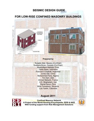
  • 1. SEISMIC DESIGN GUIDE FOR LOW-RISE CONFINED MASONRY BUILDINGS Prepared by Roberto Meli, Mexico (Co-Chair) Svetlana Brzev, Canada (Co-Chair) Maximiliano Astroza, Chile Teddy Boen, Indonesia Francisco Crisafulli, Argentina Junwu Dai, China Mohammed Farsi, Algeria Tim Hart, USA Ahmed Mebarki, France A.S. Moghadam, Iran Daniel Quiun, Peru Miha Tomazevic, Slovenia Luis Yamin, Colombia August 2011 Confined Masonry Network A Project of the World Housing Encyclopedia, EERI & IAEE With funding support from Risk Management Solutions
  • 2. © 2011 Earthquake Engineering Research Institute, Oakland, California 94612-1934. All rights reserved. No part of this book may be reproduced in any form or by any means without the prior written permission of the publisher, Earthquake Engineering Research Institute, 499 14th St., Suite 320, Oakland, CA 94612-1934. Telephone: 510/451-0905, Fax: 510/451-5411, E-mail: eeri@eeri.org, Web site: www.eeri.org This tutorial is published by the Earthquake Engineering Research Institute, a nonprofit corporation. The objective of the Earthquake Engineering Research Institute is to reduce earthquake risk by advancing the science and practice of earthquake engineering by improving understanding of the impact of earthquakes on the physical, social, economic, political, and cultural environment, and by advocating comprehensive and realistic measures for reducing the harmful effects of earthquakes. Production of this tutorial has been supported in part by a generous contribution from Risk Management Solutions, Inc., Newark, California. This tutorial was written and reviewed by volunteers, all of whom participate in EERI and IAEE’s World Housing Encyclopedia project. Any opinions, findings, conclusions, or recommendations expressed herein are the authors’ and do not necessarily reflect the views of their organizations. ISBN: 978-1-932884-56-2 EERI Publication Number WHE-2011-02
  • 3. Seismic Design Guide for Low-Rise Confined Masonry Buildings 2 Acknowledgments These guidelines were prepared by a committee of international experts, led by Roberto Meli of Mexico and Svetlana Brzev of Canada. Other committee members were: Maximiliano Astroza, Chile; Teddy Boen, Indonesia; Francisco Crisafulli, Argentina; Junwu Dai, China; Mohammed Farsi, Algeria; Tim Hart, USA; Ahmed Mebarki, France; A.S. Moghadam, Iran; Daniel Quiun, Peru; Miha Tomazevic, Slovenia; and Luis Yamin, Colombia. Particular thanks are due to Leonardo Flores and Miguel Angel Pacheco, research engineers at the National Centre for Disaster Prevention, Mexico City. They were responsible for compiling many of the codes that were reviewed as part of this project, conducting some of the analyses and preparing the drawings and figures. The authors gratefully acknowledge comments and suggestions made by Sergio Alcocer (Mexico), Richard Klingner (USA), and Durgesh Rai (India), who were external reviewers for this document. Detailed review comments by Andrew Charleson, Editor-in-Chief of the World Housing Encyclopedia, contributed to the quality of the document and are gratefully appreciated. The authors would also like to thank Bill McEwen of the Masonry Institute of British Columbia, Vancouver, Canada, Arturo Tena Colunga, and Greg Hale, SWBR, Rochester, NY, USA who reviewed this document and gave very useful comments. The authors would also like to acknowledge the financial support of Risk Management Solutions in the early stages of this project, and in particular the enthusiastic support received from Sahar Safaie. The authors also acknowledge the ongoing support of the Earthquake Engineering Research Institute and the staff member Marjorie Greene. The authors appreciate assistance by Michael Germeraad, EERI Graduate Intern, in the editing stage of this publication. Special thanks are due the National Information Centre of Earthquake Engineering at the Indian Institute of Technology, Kanpur, India, for allowing us to incorporate part of one of their publications on confined masonry, authored by co-chair Svetlana Brzev. If you have comments on this document, please forward them to Marjorie Greene at mgreene@eeri.org.
  • 4. Seismic Design Guide for Low-Rise Confined Masonry Buildings 3 Table of Contents 1 INTRODUCTION.........................................................................................................................5 1.1 Scope and Objectives ...........................................................................................................................5 1.2 What is Confined Masonry Construction?..........................................................................................6 1.2.1 Key Components of a Confined Masonry Building..........................................................................6 1.2.2 Confined Masonry and Similar Building Technologies....................................................................7 1.3 Seismic Response of Confined Masonry Buildings ....................................................................... 10 1.3.1 Performance of Confined Masonry Buildings in Past Earthquakes.............................................. 10 1.3.2 General System Behavior............................................................................................................. 11 1.3.3 Seismic Failure Mechanisms........................................................................................................ 17 1.3.4 Seismic Response of Multi-story Confined Masonry Buildings.................................................... 21 1.3.5 Design and Construction Deficiencies Observed in Recent Earthquakes ................................... 24 2 GENERAL REQUIREMENTS...................................................................................................28 2.1 Design and Performance Objectives................................................................................................ 28 2.2 Seismic Hazard................................................................................................................................... 28 2.3 General Planning and Design Aspects ............................................................................................ 29 2.4 Materials .............................................................................................................................................. 32 2.4.1 Units.............................................................................................................................................. 32 2.4.2 Mortar ........................................................................................................................................... 34 2.4.3 Concrete ....................................................................................................................................... 34 2.4.4 Reinforcing Steel .......................................................................................................................... 34 2.4.5 Masonry........................................................................................................................................ 35 2.4.6 Testing of Masonry Materials ....................................................................................................... 36 3 GUIDELINES FOR NON-ENGINEERED CONFINED MASONRY BUILDINGS......................37 3.1 Building Components ........................................................................................................................ 37 3.1.1 Masonry Walls .............................................................................................................................. 37 3.1.2 Confining Elements (Tie-columns and Tie-beams) ...................................................................... 44 3.1.3 Additional Requirements for Buildings with Flexible Diaphragms................................................ 49 3.2 Construction Quality.......................................................................................................................... 51 CONCLUDING REMARKS..............................................................................................................52 REFERENCES.................................................................................................................................53
  • 5. Seismic Design Guide for Low-Rise Confined Masonry Buildings 4 APPENDICES A Simplified Method for Wall Density Calculation in Low-Rise Buildings 56 B Guidelines for Inspection of Confined Masonry Construction 70 C Summary of Seismic Design Provisions for Confined Masonry Buildings from Relevant International Codes and Standards 78
  • 6. Seismic Design Guide for Low-Rise Confined Masonry Buildings 5 1 Introduction 1.1 Scope and Objectives The purpose of this document is to: • Explain the mechanism of seismic response of confined masonry buildings for in- and out-of- plane seismic effects and other relevant seismic response issues, • Recommend prescriptive design provisions for low-rise buildings related to the wall layout and density, and prescribe minimum size requirements for structural components of confined masonry buildings (tie-columns, tie-beams, walls), reinforcement size and detailing, and • Provide a summary of the seismic design provisions for confined masonry buildings from relevant international codes. This document is divided into three chapters. Chapter 1 provides an overview of confined masonry construction and its components. It discusses the seismic performance of confined masonry buildings in past earthquakes, and is based largely on the publication Earthquake-Resistant Confined Masonry Construction (Brzev, 2008). Chapter 2 presents general requirements related to confined masonry construction. Chapter 3 outlines a guideline for low-rise non-engineered confined masonry buildings (up to two stories high). These buildings could be constructed without engineered design performed by qualified engineers or architects, and thus no design calculations or procedures are included. Many single-family dwellings are built in this manner. Although this guide is focused on low-rise confined masonry buildings, medium-rise engineered buildings of this type (up to five stories high) can be designed and built following the recommendations of this document and other relevant international codes and standards. However, note that additional analysis and design procedures and requirements for engineered confined masonry buildings are outside the scope of this document. It is expected that this guide will be a useful resource for design engineers and architects, academics, code development organizations and non-governmental organizations in countries in which design codes and standards do not contain seismic design provisions for confined masonry construction. This document may also be a useful reference for design engineers and other professionals in the countries where code design provisions for confined masonry construction are currently in place. This document was developed by a group of international experts in earthquake engineering and confined masonry construction. The recommendations are based on design and construction experience and research studies from countries and regions where confined masonry construction has been practiced for many decades, including Mexico, Peru, Chile, Argentina, Iran, Indonesia, China, Algeria and Slovenia. References to relevant provisions of various international standards and codes have been made in the document.
  • 7. Seismic Design Guide for Low-Rise Confined Masonry Buildings 6 1.2 What is Confined Masonry Construction? 1.2.1 Key Components of a Confined Masonry Building Confined masonry construction consists of masonry walls and horizontal and vertical reinforced concrete (RC) confining elements built on all four sides of a masonry wall panel, as shown in Figure 1. Vertical elements, called tie-columns, resemble columns in RC frame construction except that they tend to be of far smaller cross-sectional dimensions. Most importantly, these RC members are built after the masonry wall has been completed. Horizontal elements, called tie-beams, resemble beams in RC frame construction but they are not intended to function as conventional beams since confined masonry walls are load-bearing. Alternative terms, horizontal ties and vertical ties, are sometimes used instead of tie-beams and tie-columns. The key features of structural components of a confined masonry building are discussed below: • Masonry walls transmit the gravity load from the slab(s) above down to the foundation (along with the RC tie-columns). This document addresses confined masonry construction consisting of masonry walls made of solid clay bricks, hollow clay tiles, or concrete blocks. The walls act as bracing panels, which resist horizontal earthquake forces acting in-plane. The walls must be confined by RC tie-beams and tie-columns and should not be penetrated by significant openings to ensure satisfactory earthquake performance. • Confining elements (RC tie-columns and RC tie-beams) are effective in improving stability and integrity of masonry walls for in-plane and out-of-plane earthquake effects. These elements prevent brittle seismic response of masonry walls and protect them from complete disintegration even in major earthquakes. Confining elements, particularly tie-columns, contribute to the overall building stability for gravity loads. • Floor and roof slabs transmit both gravity and lateral loads to the walls. In an earthquake, floor and roof slabs behave like horizontal beams and are called diaphragms. The roof slabs are typically made of reinforced concrete (see Figure 1 a), but light-weight roofs made of timber or light gage steel as shown in Figure 1 b are also used. • Plinth band transmits the load from the walls down to the foundation. It also protects the ground floor walls from excessive settlement in soft soil conditions and the moisture penetration into the building. • Foundation transmits the loads from the structure to the ground. It should be noted that the term “confined masonry” is also used in a general sense for different forms of masonry construction reinforced with additional steel, timber, or concrete elements, however those construction practices are outside the scope of this document.
  • 8. Seismic Design Guide for Low-Rise Confined Masonry Buildings 7 a) b) Figure 1. A typical confined masonry building: a) flat RC roof (Brzev, 2008), and b) pitched timber roof (Boen, 2009). 1.2.2 Confined Masonry and Similar Building Technologies Confined masonry building technology is somewhat similar to both reinforced masonry and reinforced concrete frame construction with infill walls. It should be noted, however, that differences between these building technologies are significant in terms of construction sequence, complexity, and seismic performance. Since features of confined masonry construction practice are not well known on a global scale, a comparison of these building technologies is presented next. Reinforced Masonry and Confined Masonry: A Comparison In reinforced masonry, vertical and horizontal reinforcing bars are provided to enhance the strength and ductility (deformability) of masonry walls. Masonry units are usually hollow and made either of concrete or clay. Vertical reinforcing bars are placed in the hollow cores, which are subsequently grouted with a cement-based grout to anchor the reinforcement and protect it from corrosion. Vertical reinforcement is placed at the wall corners and intersections, around the openings, and at additional locations depending on expected seismic loads. Horizontal reinforcement is provided in the form of ladder-shaped wire reinforcement placed in horizontal joints, or deformed reinforcing bars placed in bond beams, typically located at floor and/or lintel levels. In confined masonry, the reinforcement is concentrated in vertical and horizontal RC confining elements whereas the masonry walls are usually free of reinforcement. Figure 2 illustrates the difference between reinforced and confined masonry construction. Advanced construction skills and inspection at different stages of construction are necessary to ensure quality of reinforced masonry. For example, vertical wall reinforcement placed in the hollow cores in masonry blocks must be continuous from the foundation to the roof level, and must match dowels (vertical bars) extended from the foundation. Subsequently, hollow cores (cells) in reinforced masonry blocks need to be filled with cement-based grout with specific mix proportions for placing it into relatively small-sized cores. Horizontal reinforcement is placed into bond beam blocks which also need to be grouted. Specialized equipment is used for pumping grout into masonry. Confined masonry is a simpler and
  • 9. Seismic Design Guide for Low-Rise Confined Masonry Buildings 8 more forgiving building technology, since the use of steel reinforcement and concrete is limited to confining elements (vertical tie-columns and horizontal tie-beams). The quality of RC confining elements in terms of reinforcement detailing and concrete construction can be verified with more confidence compared to similar components of reinforced masonry construction (e.g. placement of reinforcement and grout in hollow block cores). a) b) Figure 2. Masonry building technologies: a) confined masonry construction in Chile (S. Brzev), and b) reinforced masonry construction in Canada (B. McEwen). RC Frames with Masonry Infill Walls and Confined Masonry: A Comparison The appearance of a finished confined masonry construction and a RC frame infilled with masonry wall panels may look alike, however these two construction systems are substantially different, as illustrated in Figure 3 (note that Figure 3a shows features of RC frames with infills, while Figure 3b shows confined masonry construction). The main differences are related to i) the construction sequence, and ii) the manner in which these structures resist gravity and lateral loads. The differences related to the construction sequence are as follows: • In confined masonry construction, masonry walls are constructed first, one story at a time, followed by the cast in-place RC tie-columns. Finally, RC tie-beams are constructed on top of the walls, simultaneously with the floor/roof slab construction. • In RC frame construction infilled with masonry wall panels, the frame is constructed first, followed by the masonry wall construction. It is important to explain why seismic response of confined masonry buildings is different from RC frames with masonry infills. The main reasons are summarized below: • Due to smaller cross-sectional dimensions, RC tie-columns in confined masonry construction are slender and cannot provide an effective frame action. Tie-beam-to-tie- column connections are pinned (similar to post-and-beam timber construction), as opposed to the moment connections in RC frames. Beams and columns in RC frame construction are much larger in size, and they have significantly larger stiffness relative to the infill. • Tie-columns are cast against a rough (toothed and/or doweled) surface, and thus are integrated into the masonry wall in confined masonry construction. On the contrary, infill walls are usually not integrated into a RC frame - there is no toothing and there are rarely any dowels. • Gravity loads in confined masonry construction are mostly supported by the masonry walls, while infills in RC frames bear mostly self-weight. Due to the significant frame
  • 10. Seismic Design Guide for Low-Rise Confined Masonry Buildings 9 stiffness, only a small portion of the floor load is transferred to the infills. Also, in infill construction it is not uncommon to have gaps between the masonry blocks and the concrete beams. These gaps are created when the blocks do not fit tightly to the underside of the beams. These gaps allow the beams to deflect without transferring the gravity loads to the wall below. • When subjected to lateral seismic loads, walls in confined masonry buildings act as shear walls, similar to unreinforced or reinforced masonry walls or RC shear walls. On the other hand, infill wall panels in RC frame buildings do not act as shear walls - they act as diagonal struts. The gaps, due to a relative lack of bond between the masonry infill and the RC frame, drastically minimize the capability of infill walls from resisting the lateral forces in a seismic event, as illustrated in Figure 3 a. Note that these gaps may already exist before an earthquake due to construction tolerances. 1 2 1 2 Infill wall Load bearing wall column tie-column beam tie-beam Infill wall Load bearing wall a) b) Figure 3. A comparison of RC frames with masonry infills (a), and confined masonry construction (b): construction sequence (top); size of confining elements (middle), and the seismic response (bottom). Detailing of reinforcement in RC confining elements is relatively simple, however the placement of concrete may be challenging due to smaller dimensions of these elements compared to traditional RC construction. It is easier to perform an inspection of concrete construction in a confined masonry building compared to an RC frame building or a reinforced block masonry building. Reasons for this include the fact that the reinforcing in a confined masonry construction is much simpler, lower strength concrete can often be used, and the hollow cores within the masonry blocks do not need to be fully aligned. Due to a lower consumption of steel and cement, construction of a confined masonry building is expected to be more economical compared to an otherwise similar RC
  • 11. Seismic Design Guide for Low-Rise Confined Masonry Buildings 10 frame building with masonry infills (particularly in developing countries where labor is relatively inexpensive). 1.3 Seismic Response of Confined Masonry Buildings 1.3.1 Performance of Confined Masonry Buildings in Past Earthquakes Confined masonry construction has evolved through an informal process based on its satisfactory performance in past earthquakes. The first reported use of confined masonry construction was in the reconstruction of buildings destroyed by the 1908 Messina, Italy earthquake (M 7.2), which killed over 70,000 people. Over the last 30 years, confined masonry construction has been practiced in Mediterranean Europe (Italy, Slovenia, Serbia), Latin America (Mexico, Chile, Peru, Colombia, Argentina, and other countries), the Middle East (Iran, Algeria, Morocco), South Asia (Indonesia), and the Far East (China). It is important to note that confined masonry construction is widely used in countries and regions of extremely high seismic hazard. Several examples of confined masonry construction around the world, from Argentina, Chile, Iran, Peru, Serbia and Slovenia, are featured in the World Housing Encyclopedia (EERI/IAEE, 2000). Well built confined masonry buildings were able to survive the effects of major earthquakes without collapse and in most cases without significant damage. Confined masonry tends to be quite forgiving of minor design and construction flaws, as well as material deficiencies provided that the buildings have regular floor plan and sufficient wall density. Poor seismic performance has been noted only where gross construction errors, design flaws, or material deficiencies have been introduced in the building design and construction process. Poor performance is usually associated with insufficient amount of confined masonry walls in one or both plan directions, inadequate size of the tie-columns, deficiencies in tie-column reinforcement in terms of amount and detailing, discontinuous tie-beams, inadequate diaphragm connections, and inappropriate structural configuration. The earliest reports describing the earthquake performance of confined masonry buildings date back to the 1939 Chile earthquake (M 7.8). In Chillán, where Modified Mercalli Intensity (MMI) of IX was reported, over 50% of all inspected confined masonry buildings survived the earthquake without any damage, whereas around 60% of unreinforced masonry buildings either partially or entirely collapsed, resulting in a death toll of 30,000. Following the 1939 earthquake, confined masonry was exposed to several significant earthquakes in Chile, including the 1985 Llolleo earthquake (M 7.8) and, more recently, the February 27, 2010 Maule earthquake (M 8.8). Low-rise confined masonry buildings performed very well in the Maule earthquake. Figure 4 a shows a two- story confined masonry house in Curepto which remained virtually undamaged, while the adjacent adobe house has collapsed (see Astroza et al. (2010) and Brzev et al. (2010) for more details on performance of confined masonry buildings in the 2010 Chile earthquake). A very similar observation was made after the 2007 Pisco, Peru earthquake (M 8.0), where confined masonry buildings performed very well compared to other types of masonry buildings which were badly damaged or collapsed. Figure 4 b shows a four-story confined masonry building in Ica, Peru which remained virtually undamaged in the earthquake. Seismic performance of confined masonry buildings in other countries will be illustrated in the following sections. Earthquake-induced life loss in confined masonry buildings has been insignificant in countries and regions where this technology has been practiced. However, a few medium-rise confined masonry buildings collapsed in recent earthquakes, e.g. the 2010 Maule, Chile earthquake and the 2007 Pisco, Peru earthquake (see Section 1.3.4 for a detailed discussion).
  • 12. Seismic Design Guide for Low-Rise Confined Masonry Buildings 11 Since confined masonry buildings performed well in past earthquakes, resources related to seismic repair and retrofit of these buildings are limited. The reader is referred to a publication developed after the 2009 Pisco, Peru earthquake (PNUD, 2009), and another one prepared after the 2002 Colima, Mexico earthquake (EERI, 2006). a) b) Figure 4. Performance of confined masonry buildings in recent significant earthquakes: a) the 2010 Maule, Chile earthquake (M.O. Moroni Yadlin), and b) the 2007 Pisco, Peru earthquake (D. Quiun). 1.3.2 General System Behavior 1.3.2.1 How Seismic Forces are Resisted by a Confined Masonry Wall Panel Seismic behavior of a confined masonry wall panel can be explained by composite (monolithic) action of a masonry wall and adjacent RC confining elements. This composite action exists due to the toothing between the walls and the tie-columns - that is one of the key features of confined masonry construction. In the absence of toothing, composite action can be achieved by means of horizontal reinforcement (dowels). Figure 5 shows a two-bay confined masonry specimen subjected to reversed cyclic lateral loading simulating earthquake effects (Pérez-Gavilán, 2009). The specimen demonstrated a typical damage pattern in the form of diagonal shear cracks. The failure took place in the form of a single diagonal crack which propagated through the walls and the tie- columns. This mechanism can be expected to occur in buildings with small RC tie-column sizes, where tie-column depth does not exceed 1.5 times the wall thickness. Figure 5. Failure of a two-bay confined masonry wall (Pérez-Gavilán, 2009).
  • 13. Seismic Design Guide for Low-Rise Confined Masonry Buildings 12 When the tie-columns and tie-beams have larger sections (depths in excess of two times the wall thickness), relative stiffness of these elements compared to the walls is significant. As a result, behavior of a confined masonry wall panel is similar to an RC frame with masonry infill wall panel. A confined masonry wall panel can be modeled using the "strut and tie" model, where a vertical crack (separation) develops between the wall and the adjoining tie-columns. At the certain load level, the wall will start to act like a diagonal strut, while the adjacent columns act in tension and/or compression, depending on the direction of lateral earthquake forces. The difference between the two cases is clearly shown in the experimental study by San Bartolomé et al. (2010), where the confined masonry wall specimens had two different tie-column widths (200 and 400 mm). A vertical separation between the wall and tie-columns occurred in the specimen M2 with 400 mm wide tie- columns. Failure mechanism of the specimen M1 with 200 mm wide columns was characterized by composite wall and tie-column action and diagonal cracking, where cracks propagated into the columns. Damage patterns in the specimens at the final stage of testing are shown in Figure 6. a) b) Figure 6. Seismic behavior of masonry walls confined by RC tie-columns: a) composite wall and tie- column action (specimen M1 with 200 mm wide tie-columns), and b) vertical separation at the wall- to-column interface (specimen M2 with 400 mm wide columns) (San Bartolomé et al. 2010). Shear capacity of a confined masonry wall panel (3) can be determined as the sum of contributions of the masonry wall (1) and the adjacent RC tie-columns (2), as shown in Figure 7. Note that the shear capacity of tie-columns can be reached only after the masonry has been severely cracked and its shear capacity has significantly decreased. As a result, it is recommended to consider only a partial contribution of tie-columns to the shear capacity of a confined masonry panel. A conservative estimate can be made by assuming that the tie-columns are integrated with the masonry wall, thus a cross-sectional area of the confined masonry wall can be calculated by taking into account the total panel length. This approach is the basis for deriving the minimum required wall density (see Appendix A of this document).
  • 14. Seismic Design Guide for Low-Rise Confined Masonry Buildings 13 It can be seen from the diagram in Figure 7 that the stiffness and strength of a confined masonry panel drop following the onset of diagonal cracking in the wall (point 1). However, the load-resisting capacity of the panel is maintained until the critical regions of the confining elements experience significant cracking (point 2). This shows that a significant lateral deformation and ductility can be attained before the failure of a properly designed and constructed confined masonry panel (point 3). Displacement Shearforce 1 2 3 1 2 3 P P P V Vm Vm V 'm Σ Vc Vc Vc V 'm Figure 7. Mechanism of shear resistance for a confined masonry wall panel: 1) diagonal cracking in the masonry wall; 2) diagonal cracks have propagated from the wall into the tie-columns, and 3) shear failure of the RC tie-columns and the confined masonry wall panel. Critical regions in a confined masonry structure are end zones of tie-columns (top and bottom region at each floor level), as shown in Figure 8 a. An example of a confined masonry wall panel which experienced significant damage in the RC tie-columns in the 2010 Chile earthquake is shown in Figure 8 b. In most cases, confined masonry panels demonstrate a shear-dominant seismic response. Longitudinal reinforcement in the RC tie-columns provides an adequate flexural resistance, thus the flexural failure mechanism does not govern; this is an assumption taken in Appendix A of this document.
  • 15. Seismic Design Guide for Low-Rise Confined Masonry Buildings 14 Masonry walls Critical regions Diagonal cracking window a) b) Figure 8. Critical regions in a confined masonry building: a) a general diagram showing critical regions in the RC tie-columns, and b) tie-column damage observed in the 2010 Chile earthquake (M. Astroza). Confined masonry panels are subjected to the effects of axial gravity load (due to self-weight and tributary floor/roof loads). Figure 9 a illustrates a confined masonry panel which resists the combined effect of axial load P and bending moment M. The capacity of the composite confined masonry panel section under the combined effect of axial load and bending moment can be determined by treating the confined masonry panel similar to a RC shear wall acting in unison with the adjacent columns. The strain diagram shows that a portion of the panel is in tension, while the remaining portion is in compression (see Figure 9 b). It is assumed that the masonry and concrete are not able to resist tension, hence tensile stresses are resisted by the longitudinal reinforcement in tie-columns. The compression stresses are resisted by concrete, masonry, and longitudinal reinforcement in tie-columns (see Figure 9 c). The flexural capacity of the panel section is determined from the sum of moments created by various internal forces around point O (centroid of the section).
  • 16. Seismic Design Guide for Low-Rise Confined Masonry Buildings 15 Compression steel Tension steel Tension Compression Compression masonry Compression concrete h V P M = Vxh P a) b) c) M P O Figure 9. A confined masonry wall panel subjected to the combined axial load and bending: a) panel elevation and a typical cross-section; b) strain distribution, and c) internal force distribution. 1.3.2.2 The Effect of Floor and Roof Systems The seismic response of a confined masonry building and the internal distribution of earthquake forces depend on the type of floor and/or roof system. Floor and roof systems are horizontal elements of the lateral load-resisting system that act as diaphragms. Their primary role is to transfer earthquake-induced lateral forces in the building to vertical elements (shear walls) that resist these forces. A diaphragm can be treated as an I-shaped beam laid in the horizontal plane. The floor or roof functions as the web to resist the shear forces, while the boundary elements (tie- beams in confined masonry buildings) act as the flanges and resist tension and compression stresses due to bending moments. The manner in which the total shear force is distributed to the vertical elements (walls) depends on the wall rigidity relative to the diaphragm rigidity. For design purposes, diaphragms are usually treated either as flexible or rigid. Timber or light gage steel diaphragms are generally considered as flexible (unless bracing is provided in the plane of the diaphragm), while cast in-place concrete or composite masonry and concrete floor systems are usually considered as rigid diaphragms. In buildings with flexible diaphragms, the distribution of shear forces to walls is independent of their relative rigidity. These diaphragms act like a series of simple horizontal beams spanning between the walls, as shown in Figure 10 a. A flexible diaphragm must have adequate strength to transfer the shear forces to the walls, but cannot distribute torsional forces to the walls in the direction perpendicular to the earthquake ground motion. Flexible diaphragms are not common in confined masonry buildings, with the exception of countries in warm climate regions, e.g. Indonesia, Chile, etc., where timber trusses have been routinely used for the roof construction. An example of a confined masonry building with a flexible timber roof diaphragm is shown in Figure 1 b. Seismic
  • 17. Seismic Design Guide for Low-Rise Confined Masonry Buildings 16 response of confined masonry buildings with flexible diaphragms and the key factors influencing the response were studied by Hart et al. (2010). In buildings with rigid diaphragms, shear forces in the walls are in direct proportion to the wall rigidity (relative to the rigidity of other walls laid in the same direction), as shown in Figure 10 b. In low-rise buildings, wall rigidity is proportional to its cross-sectional area (A), as indicated in the figure. (Note that this distribution applies only to low-rise buildings where shear response is predominant in the walls.) Torsional effects need to be considered, and may increase seismic forces in some of the walls. Buildings with rigid diaphragms are very common in most countries where confined masonry has been practiced. Figure 1 a shows RC floor and roof slabs which act like rigid diaphragms. W1 W3 W2 W1 W3 W2 B B νV = νB V = νB ν V/4 V/2 V/4 A1 V A ΣA 1 ΣA = A +A +A1 ν V/4 V/2 V/4B/2 B/2 W1 W2 W3 W1 W2 W3 Flexible diaphragm Rigiddiaphragm V A ΣA 2 V A ΣA 3 A2 A3 2 3 V = νB V A ΣA 1 V A ΣA 2 V A ΣA 3 a) b) V = νB Figure 10. Distribution of lateral loads in buildings: a) flexible, and b) rigid diaphragms.
  • 18. Seismic Design Guide for Low-Rise Confined Masonry Buildings 17 1.3.3 Seismic Failure Mechanisms 1.3.3.1 Introduction Failure mechanisms in confined masonry wall panels depend on the direction of earthquake loading. There are two possible scenarios: a) Earthquake ground shaking in the direction parallel with the longitudinal wall axis, also known as in-plane seismic loading, or b) Earthquake ground shaking perpendicular to the longitudinal wall axis, or out-of-plane seismic loading. Seismic response of confined masonry structures subjected to in-plane and out-of-plane seismic loading is discussed in the following sections. 1.3.3.2 In-plane Failure Mechanisms A confined masonry wall subjected to in-plane lateral earthquake loading develops either a shear or flexural failure mechanism (Tomazevic and Klemenc, 1997; Tomazevic, 1999; Yoshimura et al. 2004). Shear failure mechanism is characterized by distributed diagonal cracking in the wall. The damage is caused either by the bond destruction at the mortar-brick interface (shear-friction mechanism), or tensile cracking in the masonry units. Initially, a masonry wall panel resists the effects of lateral earthquake loads while the RC tie-columns do not play a significant role. However, once cracking takes place, the wall pushes the tie-columns sideways. At that stage, the vertical reinforcement in the tie-columns resists tension and compression stresses (Tomazevic and Klemenc, 1997). Damage in the tie-columns at the ultimate load level is concentrated at the top and bottom of the panel. Shear failure can lead to severe damage in the masonry wall and at the top and bottom of the tie-columns, as shown in Figure 11. (Note that this mechanism was also discussed in Section 1.3.2.1.) Figure 11. Shear failure of confined masonry walls (Yoshimura et al., 2004 – left; Aguilar and Alcocer, 2001 – right). In-plane shear failure of ground floor confined masonry walls is the most common damage pattern observed in past earthquakes, e.g. the 1999 Tehuacán and the 2003 Tecomán, Mexico earthquakes, the 2001 San Salvador, El Salvador earthquake, and the 2010 Maule, Chile earthquake. Figure 12 a shows damage at the ground floor level of a three-story building in Cauquenes. The building was constructed in 1993, before the 1997 edition of Chilean code NCh2123, which contains relevant design restrictions for confined masonry buildings, had been issued. Figure 12 b shows shear failure of a pier in a confined masonry building due to the 2001 El Salvador earthquake (note absence of RC tie-columns at openings).
  • 19. Seismic Design Guide for Low-Rise Confined Masonry Buildings 18 a) b) Figure 12. In-plane shear failure of poorly confined masonry walls: a) the 2010 Maule, Chile earthquake (M. Astroza), and b) the 2001 El Salvador earthquake (EERI, 2001). Flexural failure mechanism due to in-plane lateral loads is characterized by horizontal cracking of the mortar bed joints located on the tension side of the wall, as shown in Figure 13 (Yoshimura et al. 2004). Separation of the tie-columns from the wall was observed in some cases when a toothed wall-to-column connection was absent, and there were no connecting ties between the tie-column and the wall. Extensive horizontal cracking in tie-columns and shear cracking in the walls can be observed in Figure 13. Flexural mechanism is not as critical as shear mechanism since it does not lead to brittle failure, although crushing and disintegration of masonry in the compression toe area of the wall may take place. Figure 13. Flexural failure of confined masonry walls (Yoshimura et al., 2004). RC tie-columns have a critical role in resisting the gravity loads in damaged confined masonry buildings, and in ensuring their vertical stability (Alcocer, 2006). Due to their high axial stiffness and tension/compression load resistance, tie-columns resist a major portion of gravity load after the walls experience severe damage. The failure of a tie-column usually takes place when cracks propagate from the masonry wall into the tie-column and shear it off. Note that the failure of tie- column could take place either due to the flexural failure mechanism (shown in Figure 13), or shear failure mechanism observed in the 2010 Maule, Chile earthquake (see Figure 14 a). It has been observed that the number of ties at the tie-beam-to-tie-column joint, and the detailing of the longitudinal reinforcement appear to play a role in the tie-column shear resistance. Buckling of longitudinal reinforcement was observed when size and/or spacing of ties at the ends of tie- columns were inadequate (or when the crushing of the masonry units took place), as shown in Figure 14 b.
  • 20. Seismic Design Guide for Low-Rise Confined Masonry Buildings 19 a) b) Figure 14. Failure of RC tie-columns in the 2010 Maule, Chile earthquake: a) shear failure at the ends of a RC tie-column, and b) buckling of longitudinal reinforcement at the base of a RC tie- column (S. Brzev). 1.3.3.3 Out-of-plane Seismic Effects on the Walls Seismic shaking in the direction perpendicular to a masonry wall (also known as out-of-plane seismic loading) causes bending and shear stresses in the wall. This may result in cracking of the wall and possible collapse by overturning (toppling). Due to an increase in spectral accelerations up the building height, the out-of-plane seismic effects are more pronounced at higher floor levels, as shown in Figure 15 a. In the area affected by the 2010 Maule, Chile earthquake, wall cracking due to out-of-plane seismic effects was observed at the top floor level, as shown in Figure 15 b (no damage was observed at lower floors in the same direction). The building had RC floor slabs and timber truss roof system. (Note that this the same building suffered extensive damage in the longitudinal direction at the ground floor level, as shown in Figure 12 a.) The extent of damage and a likelihood of wall collapse depend on the type of roof and floor diaphragm (rigid or flexible), and how well the wall is attached to its confining elements (if any). The out-of-plane bending mechanism is critical mainly for buildings with flexible diaphragms, which are not capable of transmitting the lateral forces to the stiffer walls oriented in the direction of seismic action. In some cases, this mechanism can also be critical in buildings with rigid diaphragms due to inertia forces generated by transverse wall vibrations (see Figure 15 a). To prevent the out-of-plane wall failure, it is important to restrict the maximum spacing of tie-beams and tie-columns, and ensure toothing/interaction between the walls and the confining elements, as discussed in this document.
  • 21. Seismic Design Guide for Low-Rise Confined Masonry Buildings 20 More pronounced response at higher levels a) b) Figure 15. Out-of-plane seismic response of confined masonry walls: a) a mechanism of seismic response (Tomazevic, 1999, and b) observed damage at the top floor level of a building after the 2010 Maule, Chile earthquake (M. Astroza). A possible out-of-plane failure mechanism for walls in buildings with rigid diaphragms is similar to that characteristic of a two-way slab supported on all sides and subjected to uniformly distributed loading, as shown in Figure 16 a. This damage pattern was observed at the second floor level of a three-storey building damaged in the 2010 Maule, Chile earthquake, as shown in Figure 16 b. Failure mechanisms for out-of-plane wall response are discussed in more detail in Section 3.1.3 of this document. L h Tie-beam RC slab (rigid diaphragm) Tie-column Seismic force 45° Transverse wall a) b) Figure 16. Out-of-plane seismic effects in confined masonry walls: a) two-way slab mechanism, and b) evidence from the 2010 Maule, Chile earthquake (S. Brzev). RC tie-beams have an important role in enhancing the out-of-plane resistance of confined masonry walls in buildings with flexible diaphragms. These beams need to have adequate size and reinforcement (in terms of amount and detailing), as discussed in Section 3.1.3. Failure of a free- standing confined masonry fence in Santa Cruz due to the 2010 Maule, Chile earthquake is a good example of the out-of-plane wall collapse due to inadequate size of RC tie-beams and inadequate lap splice length, as shown in Figure 17.
  • 22. Seismic Design Guide for Low-Rise Confined Masonry Buildings 21 a) b) Figure 17. Collapse of a confined masonry fence in the 2010 Maule, Chile earthquake due to out- of-plane seismic effects: a) collapsed fence showing the RC tie-beam failure, and b) detail of RC tie-beam showing excessively short lap splice length in the longitudinal reinforcement (M. Astroza). The out-of-plane failure of confined masonry walls has also been observed in buildings with flexible roof/floor diaphragms which are common in Indonesia. 1.3.4 Seismic Response of Multi-story Confined Masonry Buildings Earthquake-induced lateral forces in multi-story confined masonry buildings, peak at the ground floor level and may cause significant shear cracking. Under severe earthquake ground shaking, the collapse of a confined masonry building may take place at the first story level, as shown in Figure 18. Note that this mechanism is different from the soft-story collapse mechanism which is found in RC frames with masonry infill walls. In a confined masonry building the stiffness is initially equal at all floor levels, however the collapse occurs at the first story level due to high seismic loads, which cause extensive masonry cracking and a resulting decrease in the lateral stiffness. This behavior was confirmed by experimental studies (Ruiz and Alcocer, 1998; Alcocer et al., 2004, 2004a). Figure 18. Collapse mechanism for multi-story confined masonry buildings (Alcocer et al., 2004). In the area affected by the February 2010 Maule, Chile earthquake (M 8.8), a few multi-story confined masonry buildings experienced significant damage at the ground floor level. Two three- story buildings collapsed at the first story level, killing ten people in total. One of the collapsed
  • 23. Seismic Design Guide for Low-Rise Confined Masonry Buildings 22 buildings was located in Santa Cruz, where the maximum observed seismic intensity on the MSK scale was 7.5; note that the maximum MSK intensity of 9.5 was reported in the earthquake-affected area (Astroza et al., 2010). The building was a part of the complex consisting of 32 identical buildings (two rows of 16), as shown in Figure 19 a. Several factors influenced seismic performance of this building and likely led to its collapse. The building was characterized by inadequate wall density (less than 1 % calculated on a floor basis), which is significantly less than the values recommended in this document. The absence of confining elements around openings resulted in insufficient number of confined wall panels which contribute to lateral load resistance. In addition, poor quality of construction was observed in a few other buildings within the same complex -- this resulted in inadequate shear strength of masonry walls. Exterior masonry walls were built using hollow concrete blocks, while the interior walls were built using hand-made solid clay bricks. Wall thickness was 150 mm and the RC tie-columns were of square shape with 150 mm cross-sectional dimension. The collapsed building lost its ground floor, as shown in Figure 19 b. a) b) Figure 19. Collapse of a three-story confined masonry building in Santa Cruz, Chile due to the February 2010 Maule earthquake: a) building complex, and b) a building that experienced collapse at the ground floor level (S. Brzev). The other collapsed building was located in Constitución, which was affected both by the earthquake and the subsequent tsunami; note that the maximum observed seismic intensity on the MSK scale was 9.0 (significantly higher than Santa Cruz) (Astroza et al., 2010). The collapsed building was a part of a complex of three buildings (A, B, and C) built atop a hill in the proximity of a steep slope, as shown in Figure 20 a. Building C located closest to the slope (5 m distance on the west side) collapsed, while buildings A and B suffered damage. The collapsed building C lost its bottom floor and moved by approximately 1.5 m in the north direction (towards the slope), as shown in Figure 20 b. Note that building B (located closer to building C) experienced more extensive damage than building A. The damage in all buildings was more pronounced in the north-south direction (transverse direction of the building plan). The walls were constructed using hollow clay blocks, and the thickness was 140 mm. RC tie-columns had different cross-sectional dimensions depending on the location; the depth was in the range from 140 to 200 mm, and width was equal to the wall thickness. In addition, a few wide RC columns were placed instead of tie-columns at some locations and were continuous up the building height -- this practice is followed in medium-rise confined masonry construction in Chile. Cross-sectional depth of these wide columns varied from 700 to 900 mm and the width was 140 mm (equal to the wall thickness). The columns were reinforced with vertical and horizontal reinforcement, similar to RC shear walls but without seismic detailing.
  • 24. Seismic Design Guide for Low-Rise Confined Masonry Buildings 23 It is believed that the building location and geotechnical effects were the key factors contributing to the collapse. In addition, a relatively low wall density in the north-south direction (less than 1 % calculated on a floor basis) and a few deficiencies in the detailing of RC confining elements, were also observed. a) b) Figure 20. Collapse of a three-story confined masonry building in Constitución, Chile due to the February 2010 Maule earthquake: a) an aerial view of buildings A, B and C (note a steep slope on the north-west side shown with a solid line), and b) building C (located closest to the slope) lost the ground floor and moved by approximately 1.5 m away from the plinth towards north (S. Brzev). Collapse of a four-story confined masonry building was also reported in the 2007 Pisco, Peru earthquake (M 8.0) (San Bartolomé and Quiun, 2008). The interior walls in the transverse direction were discontinued at the ground floor level to provide parking space, as shown in Figure 21. The building collapsed at the ground floor level due to torsional effects. Figure 21. Collapse of a four-story confined masonry building in the 2007 Pisco, Peru earthquake (San Bartolomé and Quiun, 2008). After the 2003 Tecomán (Colima), Mexico earthquake (M 7.8), a three-story confined masonry apartment building in Colima experienced significant damage at the ground floor level (EERI, 2006). Similar observations related to seismic performance of multi-story confined masonry buildings were made after the 2008 Wenchuan, China earthquake (M 7.9).
  • 25. Seismic Design Guide for Low-Rise Confined Masonry Buildings 24 1.3.5 Design and construction deficiencies observed in recent earthquakes Recent damaging earthquakes, including the January 12, 2010 Haiti earthquake (M 7.0) and the February 27, 2010 Maule, Chile earthquake (M 8.8) have confirmed the notion that confined masonry buildings can show satisfactory earthquake performance when constructed according to requirements of various codes and guidelines. A few typical deficiencies related to confined masonry construction observed in the Chile earthquake are outlined below (this section is based on Brzev et al., 2010). Inadequate quality of masonry materials and construction was observed in a few severely damaged buildings. Poor performance of confined masonry walls built using hollow concrete blocks was observed in several instances; this was mostly due to poor quality of concrete block units, as shown in Figure 22 a. Confined masonry walls built using unreinforced hollow concrete blocks have shown poor performance in past earthquakes, including the 2010 Haiti earthquake. These walls experienced crushing after the diagonal cracking has taken place, thus causing significant post- cracking strength and stiffness degradation. It is acknowledged that the quality of these concrete blocks is substandard in some countries and regions due to the manufacturing method which consists of inadequate grading and proportioning of mix ingredients and inadequate curing. Hollow masonry units should be used with caution in non-engineered buildings. Masonry walls built using low-strength hollow concrete blocks are more prone to brittle failures compared to the walls built using solid concrete and clay units. When hollow concrete blocks are used for confined masonry construction, it is critical to ensure that the minimum material strength and construction quality recommendations outlined in Section 2.4 of this document have been met. Also, wall density index requirements outlined in Section 3.1.1.1 are by 33% higher for confined walls built using hollow concrete blocks compared to solid units. In some instances, excessively thick mortar bed joints (on the order of 30 mm) were observed in brick masonry walls, as shown in Figure 22 b; such masonry is expected to have a substandard compression and shear strength. a) b) Figure 22. Poor quality of masonry construction: a) low-strength concrete blocks, and b) excessively thick mortar bed joints in brick masonry construction (Brzev et al., 2010). Inadequate confinement at the ends of RC tie-columns was observed in several instances, as shown in Figure 23. An enhanced confinement in the end zones of RC tie-columns can be achieved by providing closely spaced ties (see Figure 50). This is critical for preventing premature buckling
  • 26. Seismic Design Guide for Low-Rise Confined Masonry Buildings 25 when increased axial compression stresses develop in localized areas where masonry has been completely disintegrated. Note that closer spacing of ties in the end zones of RC tie-columns is also very important for preventing shear failure in these elements. Absence of ties in the joint region was observed in all cases when joints were exposed (see Figure 24 a). This deficiency caused a shear failure in the joint region, as shown in Figure 24 b. Figure 23. Buckling of longitudinal reinforcement due to inadequate confinement in the end zones of RC tie-columns (Brzev et al., 2010). a) b) Figure 24. Inadequate detailing of the tie-beam longitudinal reinforcement and an absence of confinement in the tie-beam-to-tie-column joint region: a) interior tie-column, and b) exterior tie- column (Brzev et al., 2010). Discontinuous longitudinal reinforcement at the RC tie-beam intersections can be seen in Figure 25 a, which shows a damaged tie-beam joint in a typical "corner building" in Chile. A detail of discontinuous horizontal tie-beam reinforcement is shown in Figure 25 b. Reinforcement cages for
  • 27. Seismic Design Guide for Low-Rise Confined Masonry Buildings 26 tie-beams and tie-columns are often assembled off the building site, however additional “continuity reinforcement” should be provided in the joint area after the cages are placed in their final position. a) b) Figure 25. Inadequate anchorage of tie-beam reinforcement: a) typical “corner” building, and b) tie- beam intersection showing a discontinuity in the longitudinal reinforcement (Brzev et al., 2010). Absence of RC tie-columns at openings was observed in several buildings, as shown in Figure 26. This deficiency resulted in extensive damage of masonry piers. Presence of RC tie-columns at openings enables the development of compressive struts in masonry wall panels; this is the key mechanism for lateral load transfer in confined masonry walls. Masonry wall panels without RC tie- columns at both ends are considered to be unconfined. As a result, these panels are not to be considered in wall density calculations (as discussed in Section 3.1.1.1). Figure 26. Absence of RC tie-columns at openings (Brzev et al., 2010). The effect of RC confining elements at the openings can be observed in two apartment buildings located in Santiago. The building shown in Figure 27 a had RC tie-columns at the ends of the openings (note the concrete in the tie-column at the right was formed to mimic brick masonry appearance). The other building, shown in Figure 27 b, had a RC tie-column placed in the middle of the pier, which was unnecessary (note the absence of tie-columns at the ends of openings). The
  • 28. Seismic Design Guide for Low-Rise Confined Masonry Buildings 27 walls in the first building experienced moderate cracking, while severe cracking was reported in most piers at the first story level of the latter building. a) b) Figure 27. In-plane shear cracking of piers in confined masonry walls: a) a confined masonry panel with RC tie-columns at both ends (note RC tie-column highlighted with a black ellipse), and b) unconfined opening (note RC tie-column at the middle of the pier highlighted with a red ellipse) (Brzev et al., 2010).
  • 29. Seismic Design Guide for Low-Rise Confined Masonry Buildings 28 2 General Requirements 2.1 Design and Performance Objectives Seismic provisions of most modern building codes are based on the “life safety” performance objective: extensive structural damage is acceptable in a severe earthquake, but collapse should be avoided so the occupants can safely evacuate the building. The recommendations in this guide are based on the life safety performance objective. Properly designed and constructed, confined masonry buildings with sufficient wall density are not expected to experience damage due to moderate earthquakes. 2.2 Seismic Hazard Seismicity levels in this document are based on the global seismic hazard map developed by the Global Seismic Hazard Program (GSHAP) shown in Figure 28. This information can be used in the absence of country or region-specific seismic hazard information often provided by national codes or seismological studies. Peak ground acceleration (PGA) is defined for hard soil conditions at various global localities. Note that the PGA magnitude at a specific site location depends on the type of soil, which is not taken into account by the GSHAP map. The GSHAP seismic hazard levels (low, moderate, high and very high) are summarized in Table 1. Design provisions outlined in Chapter 3 of this guide are focused on confined masonry construction located in regions of moderate and high seismic hazard. For regions of low seismic hazard, it is expected that the building design is not governed by seismic effects (it is more often governed by gravity loads). On the other hand, in regions of very high seismic hazard it is assumed that a specific seismic hazard study is needed to determine the PGA and/or the design spectra for confined masonry buildings. Therefore, Table 1 does not contain the maximum PGA value for regions of very high seismic hazard. Table 1. Seismic hazard levels (based on the GSHAP). Seismic Hazard Level PGA (m/sec2 ) PGA (g) Low PGA≤0.8 m/sec2 PGA≤0.08g Moderate 0.8 m/sec2 <PGA≤2.4 m/sec2 0.08g<PGA≤0.25g High 2.4 m/sec2 <PGA≤4.0 m/sec2 0.25g<PGA≤0.4g Very High PGA>4.0 m/sec2 PGA>0.4g
  • 30. Seismic Design Guide for Low-Rise Confined Masonry Buildings 29 Figure 28. Global seismic hazard map (GSHAP). 2.3 General Planning and Design Aspects Experience from past earthquakes has confirmed that the conceptual design of a building is critical for its satisfactory performance. Architects play an important role in developing the conceptual design which defines the overall shape, size and dimensions of a building. Structural engineers are responsible for analyzing structural safety, and must work closely with architects to ensure that the design meets both structural and architectural requirements. Engineers are often not involved in design of low-rise buildings such as the confined masonry buildings discussed in this guide. When architects are involved, they usually work directly with the builders throughout the construction process. Therefore, it is critical for architects and builders to follow simple rules for the design and construction of confined masonry buildings. A regular building layout is one of the key requirements for its satisfactory earthquake performance. Desirable and undesirable solutions are outlined below. The material in this section is largely based on the publications by Blondet (2005) and Brzev (2008). 1) The building plan should be of a regular shape (see Figure 29). No Yes RegularIrregular Figure 29. Regular building plan. 2) The building should not be excessively long. Ideally, the length-to-width ratio in plan should not exceed 4 (see Figure 30).
  • 31. Seismic Design Guide for Low-Rise Confined Masonry Buildings 30 YesNo Less than 4 times the width Width More than 4 times the width Width Figure 30. Building length-to-width aspect ratio. 3) The walls should be built in a symmetrical manner to minimize torsional effects. Note that it is not always possible to have a perfectly symmetrical wall layout – the one shown on the right in Figure 31 is not ideal, but is much better than the layout shown on the left. YesNo Figure 31. Wall layout. 4) Since the earthquake performance of confined masonry buildings largely depends on the shear resistance of masonry walls, it is essential that a sufficient number and total length of walls be provided in each direction. Figure 32 (a and b) show building plans with inadequate wall distribution. To avoid twisting (torsion) of the building in an earthquake, the walls should be placed as far apart as possible, preferably at the exterior of the building, as shown in Figure 32 (c and d).
  • 32. Seismic Design Guide for Low-Rise Confined Masonry Buildings 31 N Yes a) b) c) d)No Figure 32. Wall distribution in plan: a) and b) not enough walls in the E-W direction; c) and d) possibly adequate wall lengths in both N-S and E-W directions (note a few strong walls on the perimeter of the plan). 5) The walls should always be placed continuously, directly over one another. Figure 33 (left) shows walls that are offset, while Figure 33 (right) shows vertically continuous walls. Continuous walls YesNo Discontinuous walls Figure 33. Continuity of walls between storeys (vertical sections shown).
  • 33. Seismic Design Guide for Low-Rise Confined Masonry Buildings 32 6) Openings (doors and windows) should be placed in the same position on each floor, as illustrated in Figure 34. Inadequate location of window and door openings YesNo Adequate location of openings with tie-beams and tie-colums Figure 34. Location of openings in a building. 2.4 Materials 2.4.1 Units 2.4.1.1 Types of Units The following types of masonry units are acceptable for confined masonry construction: 1) Solid concrete blocks, 2) Hollow concrete blocks, 3) Solid clay bricks, and 4) Hollow clay tiles (blocks). Solid masonry units are permitted to have perforations (holes). However, the ratio of net to gross area for a typical unit should be greater than 75%. The hollow units referred to in this document are those having, in their most unfavorable cross section, a net area equal to at least 50% of the gross area, and exterior face shell thickness of not less than 15 mm (see Figure 35 a). For hollow units with two to four cells, the minimum thickness of the interior webs is 13 mm. Multi-perforated units are those with more than seven perforations or cells (see Figure 35 b). For multi-perforated units having perforations of the same dimensions and distribution, the minimum thickness of the interior webs is 7 mm. Hollow masonry units should be used with caution in non-engineered buildings. To ensure satisfactory seismic performance of masonry walls built using concrete blocks, it is critical that the minimum material strength and construction quality recommendations outlined in this document have been met. Note that the wall density index requirements outlined in Section 3.1.1.1 are by 33% higher for walls built using hollow concrete blocks compared to those built using solid units. The following types of units are not recommended for confined masonry construction: 1) Masonry units with horizontal perforations, and 2) Natural stone masonry and adobe (sun-dried earthen units).
  • 34. Seismic Design Guide for Low-Rise Confined Masonry Buildings 33 gross area cell net area gross area net area ≥ 0.5 exterior face shell thickness ≥ 15 mm thickness ≥ 15 mm perforation unit height thickness of unit length of unit a) Hollow units web thickness ≥ 13 mm thickness ≥ 7 mm b) Example of multi-perforated units Figure 35. Masonry units: types and dimensions (NTC-M, 2004). 2.4.1.2 Compressive Strength Minimum recommended compressive strengths for various masonry units (fp’) are summarized in Table 2 (note that the values are based on the gross area of the unit). When technical information on locally available units indicates that the strength is significantly lower than the one provided in Table 2, proper adjustments to the design requirements should be made by qualified structural engineers. Table 2. Minimum compressive strength (fp’) for a masonry unit based on the gross area. Type of masonry unit Minimum compressive strength (fp’) MPa (kg/cm2 ) Solid concrete blocks 5 (50) Hollow concrete blocks 5 (50) Hand-made clay bricks 4 (40) Machine-made clay bricks 10 (100) Hollow clay units 10 (100) Multi-perforated clay bricks 10 (100)
  • 35. Seismic Design Guide for Low-Rise Confined Masonry Buildings 34 2.4.2 Mortar Three different types of mortar (I, II and III) can be used for confined masonry construction, as outlined in Table 3. It should be noted that hydraulic cement is commonly used for masonry wall construction. Masonry cement is pre-mixed in a plant and it consists of a mixture of Portland cement and plasticizing materials (such as limestone or hydrated or hydraulic lime), and other materials introduced to enhance one or more properties such as setting time, workability, water retention and durability. Masonry cement is not commonly used for loadbearing wall construction, except for rendering wall surfaces to avoid the mortar shrinkage cracking. When other mortar ingredients and/or mix proportions are used according to local practice, the design requirements should be adjusted by qualified structural engineers. Table 3. Mortar mix proportions and compressive strength (fj’)1 . Type of mortar Hydraulic cement Masonry cement Hydrated lime Sand Nominal compressive strength (fj’) MPa (kg/cm2 ) 1 - 0 to ¼ I 1 0 to ½ 12.5 (125) 1 - ¼ to ½ II 1 ½ to 1 7.5 (75) III 1 - ½ to 1 Notlessthan2.25,nor morethan3timesthe totalofcementitius materialsinvolume 4.0 (40) Notes: 1- Source: NTC-M, 2004 2.4.3 Concrete A minimum concrete compressive strength of 15 MPa based on cylinder testing is recommended. The concrete mix should provide high workability required for casting the small cross-sections of the RC confining elements. 2.4.4 Reinforcing Steel For longitudinal reinforcement, the use of deformed steel with a nominal yield strength of 400 MPa and an ultimate elongation of 9% (ductile steel) is recommended. In some countries, smooth (mild) steel is used for longitudinal reinforcement in concrete construction. Smooth steel bars have inferior bond properties compared to ribbed (deformed) bars, and a yield strength of smooth steel is usually significantly less than 400 MPa. When steel with a yield strength different than 400 MPa is used, reinforcement areas recommended in this document should be modified (increased or decreased) accordingly. Ties for tie-beams and tie-columns should be made using either smooth (mild) or ribbed (deformed) steel bars.
  • 36. Seismic Design Guide for Low-Rise Confined Masonry Buildings 35 2.4.5 Masonry Masonry strength has a significant influence upon the seismic resistance of a confined masonry building and life safety of its inhabitants. It is therefore extremely important to perform basic tests outlined in this section using local masonry materials; this is particularly important for projects involving several buildings. 2.4.5.1 Compressive Strength Compressive strength is a very important property of masonry, and it may be highly variable depending on local materials and construction practices. The design compressive strength (fm’) for the combinations of typical masonry units and mortars used in local housing construction practice should preferably be determined by testing prism specimens made of the masonry units and mortar used at construction sites, as shown in Figure 36 a. The prisms should be tested using the same procedures as other masonry wall applications (refer to Section 2.8.1 of NTC-M, 2004). In the absence of testing data, recommended empirical values for the design compressive strength of masonry (fm’) are provided in Table 4. It should be noted that fm’ refers to the ultimate strength intended to be used in designs based on the ultimate limit states design approach (LFRD) using load factors and strength reduction factors. When performing the wall resistance calculations, these values need to be modified by applying the resistance reduction factors specified by the pertinent national code or standard. Table 4. Design compressive strength of masonry (fm’) based on the gross area1 . Design compressive strength (fm’) MPa (kg/cm2 ) Type of Mortar Type of masonry unit I II III Solid clay bricks 1.5 (15) 1.5 (15) 1.5 (15) Hollow clay units 4.0 (40) 4.0 (40) 3.0 (30) Hollow concrete blocks 2.0 (20) 1.5 (15) 1.0 (10) Solid concrete blocks 2.0 (20) 1.5 (15) 1.5 (15) Notes: 1- Source: NTC-M, 2004 2.4.5.2 Basic Shear Strength Basic shear strength (vm) should preferably be determined by diagonal compression testing of small square wall specimens (wallets), as shown in Figure 36 b. The specimens should be made of the same masonry units and mortar as used for the construction. The specimens shall be subjected to monotonic compression loading acting along their diagonals. For more details of the testing procedure, refer to Section 2.8.2 of NTC-M (2004).
  • 37. Seismic Design Guide for Low-Rise Confined Masonry Buildings 36 H load thickness load masonry units mortar H ≅ L H L load load a) b) Figure 36. Masonry testing specimens: a) compressive strength, and b) shear strength. In the absence of test data, recommended empirical values for the basic shear strength of masonry (vm) are shown in Table 5. Table 5. Basic shear strength of masonry (vm)1 . Type of masonry unit Type of mortar Basic shear strength (vm) MPa (kg/cm2 ) I 0.35 (3.5) Solid clay bricks II and III 0.30 (3.0) I 0.30 (3.0) Hollow clay units II and III 0.20 (2.0) I 0.35 (3.5) Hollow concrete blocks II and III 0.25 (2.5) I 0.30 (3.0) Solid concrete blocks II and III 0.20 (2.0) Notes: 1- Source: NTC-M, 2004 2.4.6 Testing of Masonry Materials Masonry material testing should be performed whenever possible. The test results need to confirm that masonry units and mortar meet the minimum requirements of this guide. It is expected that testing procedures for masonry materials are included in the national standards. In the absence of such standards, the procedures specified in established codes and standards of other countries can be followed, such as the Technical Norms for Design and Construction of Masonry Structures, Mexico City (NTC-M, 2004).
  • 38. Seismic Design Guide for Low-Rise Confined Masonry Buildings 37 3 Guidelines for Non-Engineered Confined Masonry Buildings This chapter outlines recommendations for low-rise non-engineered confined masonry buildings (one- and two-story high). These buildings are usually built without input and/or design calculations performed by qualified structural engineers. In addition to the recommendations presented in this chapter, most recommendations outlined in Chapter 2 apply to non-engineered buildings. Whenever possible, the quality of materials (masonry, concrete, steel) used in construction of non- engineered buildings should be verified following the methods outlined in Chapter 2. 3.1 Building Components 3.1.1 Masonry Walls 3.1.1.1 Wall Density Requirements Wall density is a key indicator of safety for low-rise confined masonry buildings subjected to seismic and gravity loads. Evidence from past earthquakes shows that confined masonry buildings with adequate wall density were able to resist the effects of major earthquakes without collapse. The wall density is quantified through the wall density index, d, which is equal to d = AW/AP where AP is area of the building floor plan, as shown in Figure 37, and AW is equal to the cross-sectional area of all walls in one direction, that is, a product of the wall length and thickness when performing the AW calculations. It is not necessary to deduct the area of tie-columns and the area of voids in hollow masonry units for the AW calculations. It is very important to note that the wall cross-sectional area should not be included in the Aw calculation in the following cases: a) walls with openings, in which the area of an unconfined opening is greater than 10% of the wall surface area (see Section 3.1.1.2), and b) walls characterized by the height-to-length ratio greater than 1.5. The d value should be determined for both directions of the building plan (longitudinal and transverse). Seismic load Ap Aw Figure 37. Wall density index: parameters.
  • 39. Seismic Design Guide for Low-Rise Confined Masonry Buildings 38 The minimum wall density index, d, required for a given building can be determined by applying the Simplified Method outlined in Appendix A of this document. In the absence of detailed design calculations, minimum recommended values for wall density index are summarized in Table 6. Table 6. Wall Density Index d (%) for each direction of the building plan Seismic Hazard1 Low (PGA ≤ 0.08g) Moderate (PGA ≤ 0.25g) High (PGA ≤ 0.4g) Number of stories n Soil Type A, B or C Soil Type A Soil Type B and C Soil Type A Soil Type B and C Solid clay bricks2 (mortar type I, II and III3 ) Solid concrete blocks (mortar type I) 1 1.0 1.0 1.0 1.5 2.5 2 1.5 1.5 2.0 3.0 4.5 Solid concrete blocks (mortar type II and III) Hollow concrete blocks (mortar type I) Hollow clay bricks (mortar type I) 1 1.0 1.0 2.0 2.0 3.5 2 1.5 1.5 3.5 4.0 6.5 Hollow concrete blocks or hollow clay bricks (mortar type II and III) 1 1.0 1.5 2.5 3.0 5.0 2 2.0 3.0 5.0 6.0 9.5 Notes: 1 - see Section 2.2 for details on seismic hazard levels, and on how to proceed for regions of very high seismic hazard 2 - see Section 2.4.1 for requirements related to masonry units 3 - see Section 0 for the description of mortar types Soil Type: A Rock or firm soil B Compact granular soil C Soft clay soil or soft sand These d values can be used for “simple buildings” complying with the following requirements: 1. General requirements: a. uniform building plans (equal area) over the building height b. nearly symmetric wall layout in both orthogonal directions over the building height c. exterior walls extend over at least 50% of the length of each end of the building plan at each story. d. at least 75% of the building weight is supported by confined masonry walls 2. Building dimensions (see Figure 38): a. total building height not greater than 6 m (H ≤ 6 m) b. ratio of total building height to the minimum plan width not greater than 1.5 (H/W ≤ 1.5) c. ratio of length to width of the building plan not greater than 2.0 (L/W ≤ 2.0) 3. Floors and roofs act as rigid diaphragms (equivalent to a minimum 10 cm thick solid reinforced concrete slab) 4. Confined masonry walls (see Figure 38): a. masonry properties complying with the minimum requirements specified in Section 2.4 of this document,
  • 40. Seismic Design Guide for Low-Rise Confined Masonry Buildings 39 b. solid wall panels (without openings) confined with tie-columns and tie-beams on all four sides, c. walls continuous up the building height and connected to the floors/roof, and d. all masonry walls built using the same materials and properties. w2w1 W l1 l2 l3 l4 l1 + l2 + l3 + l4 ≥ 0.5L L w1 + w2 ≥ 0.5W H ≤ 6 m H / W ≤ 1.5 L / W ≤ 2 H W L Figure 38. Requirements for “simple buildings”. The minimum required wall density index for gravity loads can be determined by applying the Simplified Method outlined in Appendix A. For “simple buildings” complying with the above specified requirements, safety for both seismic and gravity loads can be ensured by using wall density index values recommended in Table 6. Note that the wall density values presented in Table 6 are more conservative than the values obtained by design calculations using the Simplified Method. Regions of very high seismic hazard are not covered in Table 6 because specific PGA values are not provided in Table 1 for this case. However, once the PGA value has been determined (as discussed in Section 2.2), the Simplified Method of Appendix A could be used to determine the required wall density index for buildings in areas of very high seismic hazard. 3.1.1.2 Walls with Openings Presence of significant openings has a negative influence upon seismic resistance of confined masonry walls, according to research evidence and reports from past earthquakes. Ideally,
  • 41. Seismic Design Guide for Low-Rise Confined Masonry Buildings 40 confining elements (RC tie-columns) should be provided on the sides of the openings, but that is not always feasible. The effect of openings on seismic performance of confined masonry structures depends on their size and location. In this document, a large opening is considered to have an area greater than 10% of the wall panel area, while a small opening has an area less than or equal to 10% of the wall panel area. Figure 39 shows a confined masonry wall panel with a large opening. The following two approaches can be followed for taking into account the effect of an opening: 1. Confining elements (RC tie-columns) are not provided at the ends of an opening, hence the panel is not considered to be confined, as shown in Figure 39 a. As a result, the panel should not be considered in wall density calculations in Section 3.1.1.1, and its contribution to seismic resistance of the building should be disregarded. 2. Confining elements are provided at the opening (as shown in Figure 39 b), and two confined masonry panels are considered in wall density calculations. Note that L denotes the total length of a confined masonry wall panel, including the tie-column depth; h denotes the wall height, and t denotes the wall thickness. Not considered in calculations L h a) Aop Aop > 0.1 L x h b) h Aop AT,1 = L1 x t AT,2 = L2 x t Aop > 0.1 L x h L2 ≥ h/1.5L1 ≥ h/1.5 L AT = 0 Figure 39. Masonry wall with a large opening: a) this is an unconfined panel - to be disregarded in wall density calculations), and b) RC tie-columns are provided at the opening and two confined wall panels can be considered in the wall density calculations. Figure 40 shows a confined masonry wall with a small opening. The effect of an opening can be taken into account in the following manner: a) The opening can be ignored when it is located outside the diagonals, as shown in Figure 40 a. The entire wall cross-sectional area can be considered in wall density calculations (area AT). b) When an opening is located at the intersection of the panel diagonals (see Figure 40 b), the panel cross-sectional area (AT) considered in wall density calculations should exclude the opening length. c) When an opening is located close to one end of the panel, the panel cross-sectional area (AT) considered in wall density calculations should use a larger pier length, as shown in Figure 40 c.
  • 42. Seismic Design Guide for Low-Rise Confined Masonry Buildings 41 h Aop < 0.1 L x h Aop h L ≥ h/1.5 h L ≥ h/1.5 L L1 ≥1 m L2 ≥1 m Aop < 0.1 L x h Aop < 0.1 L x h Aop Aop AT = L x t AT = (L1 + L2) x t L1 ≥ h/1.5 AT = L1 x t a) b) c) Figure 40. Confined masonry wall panel with a small opening: a) an opening outside the diagonals can be neglected; b) and c) opening must be taken into account. 3.1.1.3 Wall Spacing Maximum spacing of transverse walls in buildings with flexible diaphragms should not exceed • 6 m for regions of low and moderate seismicity, and • 4.5 m for regions of high and very high seismicity. Refer to Section 3.1.3 for special requirements concerning buildings with flexible diaphragms. 3.1.1.4 Wall Dimensions and Height/Thickness Ratio Restrictions • A minimum wall thickness (t) of 110 mm is required. • The maximum wall height/thickness (H/t) ratio for walls in one- and two-story buildings must not exceed 25. • The height/length ratio of a wall panel should not be less than 0.5. • The maximum wall height should not exceed 3 m. 3.1.1.5 Parapets and Gable Walls Parapets RC tie-columns and tie-beams should extend to the top of the parapet, as shown in Figure 44. When a parapet is not confined, the height should not exceed 0.5 m, otherwise the height limit is 1.2 m. Gable Walls It is recommended that the top of gable be confined with RC tie-beams and that the RC tie-columns located at the middle of the gable wall be extended from the lower floor to the top of gable wall (whenever applicable), as shown in Figure 41 a. Alternatively, a gable portion of the wall can be made of timber or other light-weight material (see Figure 41 b). To avoid cutting of masonry units, the bottom face of the gable tie-beam can be stepped.
  • 43. Seismic Design Guide for Low-Rise Confined Masonry Buildings 42 roof tie-beam tie-column gable tie-beam gable tie-beam roof a) light-weight gable panel tie-column roof tie-beam roof b) Figure 41. Gable walls: a) RC confining elements, and b) light-weight gable panel. 3.1.1.6 Toothing at the Wall-to-tie-column Interface Good bonding between a masonry wall and adjacent RC tie-columns is important for satisfactory earthquake performance, and for delaying undesirable cracking and separation at the wall-to-tie- column interface. Bonding is an essential feature of confined masonry construction and it can be achieved by toothing at the wall-to-tie-column interface, as shown in Figure 42. Toothed edges should be left on each side of the wall at the interface with the tie-columns. Toothing length should be equal to one-quarter of the masonry unit length, but not less than 5 cm1 , as shown in Figure 42 a. It is very important to clean the surfaces of "toothed" masonry units before the concrete has been poured. When hand-made bricks are used, it is desirable to cut the brick edges, as shown in Figure 42 b. Horizontal reinforcement anchored into RC tie-columns, also known as dowels, can be used as an alternative to toothing, as shown in Figure 42 c. Note that the dowels are not necessary when toothed edges are used. Toothing is required for low-strength masonry built using hand-made clay bricks and concrete blocks. Examples of field applications of toothing are shown in Figure 43. 1 Source: NT E.070, 2006; Blondet, 2005
  • 44. Seismic Design Guide for Low-Rise Confined Masonry Buildings 43 ≤ 40 cm 40 cm Details of the toothed wall edges ( ) p q 2.5 cm 3 cm Shear connectors or dowels 2.5 cm 5 cm a) b) c) Figure 42. Toothing in confined masonry walls: a) machine-made hollow units, b) hand-made solid units, and c) provision of horizontal reinforcement when toothing is not possible. a) b) Figure 43. Toothing applications: a) recommended construction practice (S. Brzev), and b) not recommended - absence of toothing in concrete block construction (C. Meisl).
  • 45. Seismic Design Guide for Low-Rise Confined Masonry Buildings 44 3.1.2 Confining Elements (Tie-columns and Tie-beams) 3.1.2.1 Spacing Tie-columns Tie-columns should be provided at the following locations: • at wall intersections, and • at ends of wall panels that provide lateral load resistance to the building. When tie-columns are provided at openings, confined masonry wall panels enclosed by these tie- columns can be taken into account in the wall density calculations discussed in Section 3.1.1.1. Spacing of tie-columns should not exceed: • 4.5 m for regions of high seismicity, and • 6 m for regions of moderate seismicity. Tie-beams A RC tie-beam must be provided at the top of each wall at the maximum spacing of 3 m. Provision of continuous RC tie-beams at intermediate (lintel/sill) levels is not necessary, but it may be beneficial for out-of-plane stability of walls with height/thickness ratio (H/t) is greater than 20. Refer to Section 3.1.3 for more details regarding the intermediate tie-beams. Recommendations regarding the location and spacing of confining elements are illustrated in Figure 44 and Figure 45. t Tie-colum n spacing: 6.0 m (m oderate seism icity) 4.5 m (high seism icity) H / t ≤ 25 t ≥ 110 mm tie-beam spacing ≤ 3.0 m slab H tie-beam in parapets ≥ 500 mm tie-columns in parapets Tie-columns at wall intersections confining elements around openings Figure 44. Key recommendations for non-engineered confined masonry buildings (adapted from NTC-M, 2004).
  • 46. Seismic Design Guide for Low-Rise Confined Masonry Buildings 45 tie-columns at wall ends and intersections tie-columns at openings door window door thickness ≥ 110 mm tie-column spacing ≤ 4.5 or 6 m Figure 45. Typical floor plan illustrating the placement of RC tie-columns (Brzev, 2008). 3.1.2.2 Minimum Dimensions • Tie-column Size (Depth x Width): 150 mm x t, where t denotes the wall thickness • Tie-beam Size: same as tie-column size 3.1.2.3 Reinforcement Requirements Longitudinal Reinforcement (Tie-beams and Tie-columns): • Minimum 4 reinforcing bars • Bar sizes: o deformed reinforcing bars of minimum 10-mm diameter (metric sizes) or #3 bars (3/8” diameter in Imperial units), or o smooth reinforcing bars of 12 mm diameter (when deformed bars are not available). To ensure the effectiveness of tie-beams in resisting earthquake loads, longitudinal bars should have a 90° hooked anchorage at intersections, as shown in Figure 46. min 50 cm min 50 cm (a) (b) Figure 46. Tie-beam construction: a) wall intersections; b) hooked anchorage for longitudinal reinforcement is a must (Brzev, 2008). Proper detailing of tie-beam-to-tie-column connections is a must for satisfactory earthquake performance of the entire building. Figure 47 shows reinforcement details at a typical interior tie-
  • 47. Seismic Design Guide for Low-Rise Confined Masonry Buildings 46 beam-to-tie-column joint. It is very important to ensure the continuity of longitudinal tie-beam reinforcement through the joint. An example of a continuous longitudinal reinforcement is shown in Figure 47 a. In some countries (e.g. Mexico, Chile, etc.), prefabricated reinforcement cages are used for tie-beam and tie-column reinforcement. In that case, additional "continuity" reinforcement must be used to provide continuity in the tie-beam-to-tie-column joint regions (see Figure 47 b). Tie-beam cross section Plan View Continuity reinforcement b) Discontinuous prefabricated cages a) Continuous tie-beam reinforcement Cage #1 Cage #2 Figure 47. Tie-beam reinforcement details: a) continuous tie-beam reinforcement, and b) continuity reinforcement must be added when prefabricated reinforcement cages are used. Reinforcing bars must be properly anchored. A typical connection detail at the roof level is shown in Figure 48. Note that the tie-column longitudinal reinforcement needs to be extended into the tie- beam as much as possible, preferably up to the underside of the top tie-beam reinforcement. A hooked anchorage is required (using 90° hooks) both for the tie-column and tie-beam reinforcement. In buildings with RC floors and roof, it is acceptable to integrate RC tie-beams into an RC floor or roof slab. ELEVATION tie-column tie-beam Figure 48. Anchorage of tie-beam and tie-column longitudinal reinforcement (Alcocer et al., 2003). When tie-beam depth exceeds 300 mm, vertical reinforcement in the RC tie-column must be confined by the ties, below and above the joint. An additional U-shaped stirrup must be placed at the tie-beam midheight, as shown in Figure 49. This detailing practice is necessary to prevent poor seismic performance illustrated in Figure 24 b.
  • 48. Seismic Design Guide for Low-Rise Confined Masonry Buildings 47 tie-beam tie-column ld U-shape ELEVATION PLAN VIEW >300mm ld Figure 49. Additional confinement for vertical reinforcement in the tie-beam and tie-column end joint region. It is not necessary to provide additional confinement for vertical reinforcement in joint regions of interior tie-columns. However, to minimize the chances of buckling in vertical reinforcing bars, it is recommended to place the first tie at the ends of tie-columns (top and bottom) as close to the joint as possible (see Figure 50 b); this recommendation applies to all seismic regions. An example of a poor construction practice resulting in earthquake damage is shown in Figure 24 a. General requirements for lap splices in longitudinal reinforcement are summarized below: • The tie-beam longitudinal reinforcement should be hooked and lapped at the ends with the intersecting reinforcement. The lap length of the hook tails should be at least 15 to 20 bar diameters. • Tie-column longitudinal bars at the roof level should be bent and lapped for at least 40 bar diameters with the tie-beam longitudinal reinforcement (see Figure 48). • Tie-column longitudinal reinforcing bars at the lower floor levels should extend far enough above the floor slab to form a lap splice of at least 40 bar diameters with the tie-column bars to be placed above. • Lap splices for longitudinal reinforcement should be at least 40 bar diameters. In tie-beams, the splices should be located at the end one-third of the beam span. The splices should be staggered so that not more than 2 bars are spliced at any one location. When the construction drawings specify 180 degree hooks at the bar ends, this should be verified through site inspection. Tie Size and Spacing (see Figure 50): • Size: minimum 6 mm diameter bars should be used (either smooth or deformed steel bars) with 135° hooked ends (staggered); note that db denotes tie diameter in Figure 50 a. • Tie spacing (s) should not exceed 200 mm - this applies to RC tie-columns and tie-beams o For regions of high and very high seismicity, reduced tie spacing (s/2) is required at the ends of tie-columns, as shown in Figure 50 b. The length over which the reduced tie spacing is used should not exceed the larger of the following two values: - 2b, where b is the tie-column dimension, or - ho/6, where ho is the tie-column clear height. o For regions of moderate seismicity, a uniform tie spacing (s) of 200 mm should be used throughout - it is not required to reduce tie-spacing at the tie-column ends. • Minimum concrete cover to ties is 20 mm.
  • 49. Seismic Design Guide for Low-Rise Confined Masonry Buildings 48 bs ≥ 20 mm 90° Hook No Yesdb b 135° Hook 6d a) h0 opening (window) s s s s/2 reduced tie spacing A B C D E s/2 s/2 s/2 s/2 s/2 b) Figure 50. Tie-column reinforcement details: a) tie layout and detailing, and b) reduced tie spacing requirements at the ends of RC tie-columns. 3.1.2.4 Construction Issues Tie-columns and tie-beams must be carefully constructed. High-slump concrete needs to be used for tie-column construction: maximum 125 mm slump is recommended. All voids in the forms must be completely filled with concrete and a high standard of compaction is required. The concrete in tie-columns can be cast continuously up the entire wall height; alternatively, concrete can be cast in three lifts when continuous casting is not possible. RC tie-columns should not be cast above the completed portion of the wall. 3.1.2.5 Foundation and Plinth Construction The foundation should be constructed in the similar manner as traditional masonry construction. Either an uncoursed random rubble stone masonry footing or an RC strip footing can be used. An RC plinth band should be constructed on top of the foundation. In confined masonry construction, a plinth band is essential to fully confine wall panels along their bases and prevent excessive wall
  • 50. Seismic Design Guide for Low-Rise Confined Masonry Buildings 49 damage due to building settlement in soft soil areas. Note that the longitudinal reinforcement should be extended from a RC tie-column into the plinth band, and whenever possible, into the foundation. Concrete block masonry units can be used for foundation construction below the ground level - it is not recommended to use other masonry units for this purpose. A few different foundation solutions are illustrated in Figure 51. Floor Plinth band min80cm min30cm 10 cm maximum slope min40cm min 40 cm Floor 10 cm min40cm 5cm Floor 10 cm min80cm min 50 cm 1.5 1 Strip footing Plinth band Tie-column Plinth band Floor 10 cmmin40cm 5cm min 50 cm Strip footingFloor 10 cm min40cm 5cm min 50 cm Strip footing d) RC footing on hard soil condition e) RC footing on soft soil condition min20cm a) Stone footing (stone and concrete) b) Stone footing (stone and mortar) c) Development length into stone footings Figure 51. Foundation details for confined masonry construction. 3.1.3 Additional Requirements for Buildings with Flexible Diaphragms Seismic shaking in the direction perpendicular to a wall causes out-of-plane vibrations and resulting stresses. Seismic performance of the confined masonry walls due to out-of-plane vibrations depends on the type of roof and floor diaphragm (rigid or flexible) (refer to Section 1.3.2.2 for a discussion on rigid and flexible diaphragms). In buildings with rigid diaphragms, walls subjected to out-of-plane seismic loads act like two-way slabs, as shown in Figure 52 a. Out-of-plane seismic shaking might cause cracking in confined masonry walls, however it is expected that the requirements for minimum size and maximum
  • 51. Seismic Design Guide for Low-Rise Confined Masonry Buildings 50 spacing of RC confining elements, set in Section 3.1.2, will ensure that failure of these walls will be avoided. When floors or roof of the building act as flexible diaphragms, the walls are unable to transfer out- of-plane loads to the supporting transverse walls and the roof/floor diaphragms. As a result, cracking or even overturning (toppling) of the walls might take place. Possible mechanisms for seismic response of confined masonry walls in buildings with flexible diaphragms are shown in Figure 52 b. The resistance of confined masonry walls to out-of-plane seismic vibrations can be enhanced in one of the following ways: a) by providing a rigid RC tie-beam at the top of the wall, b) by providing an intermediate RC tie-beam at lintel/sill levels, or c) by connecting the walls to the RC tie-columns through horizontal dowels which are specifically designed to transfer the out-of-plane loads. In buildings with flexible diaphragms, it is necessary to provide a rigid RC tie-beam at the top of each wall. The tie-beam must be able to resist significant lateral load and transfer it to the transverse walls, otherwise excessive damage and/or collapse of the wall could take place. This can be achieved by limiting the L/b ratio, where L denotes the span of the tie-beam (the distance between the adjacent transverse walls) and b denotes its width (see Figure 52 b). Transverse wall Transverse wall b b 45° Flexible diaphragm Flexible diaphragm L 45° h L Transverse wall 45° Seismic force Tie-column RC slab (rigid diaphragm) Tie-beam h L a) b) Figure 52. Mechanisms of failure for confined masonry walls under the out-of-plane seismic loads: a) buildings with rigid diaphragms, and b) buildings with flexible diaphragms. Unless specific design calculations are performed to confirm the out-of-plane wall resistance, the following requirements must be followed for confined masonry buildings with flexible diaphragms: 1. Roof and floor must be light-weight, e.g. made of timber or thin cold-formed steel sheets (also known as corrugated galvanized iron sheets). 2. The building height should not exceed two stories for regions of moderate seismic hazard, and one story for regions of high and very high seismicity. 3. The L/b ratio should not exceed the following values: a) for regions of moderate seismicity: 25 for one-story buildings, and 20 for two-story buildings.
  • 52. Seismic Design Guide for Low-Rise Confined Masonry Buildings 51 b) for regions of high or very high seismicity: the limit is set to 20 (irrespective of the building height). Note that L denotes the distance between the adjacent transverse walls when L/h ≥ 1.0, otherwise the wall height h should be used instead of L (see Figure 52 b for the notation). 4. The minimum width of a RC tie-beam, b, must not be less than the following values: • 20 cm • L/30 for regions of moderate seismicity, and • L/20 for regions of high and very high seismicity. Out-of-plane resistance of confined masonry wall panels can also be enhanced by providing horizontal dowels or intermediate RC tie-beams (bands). Horizontal dowels are shown in Figure 42 c, however it is preferred to provide intermediate RC tie-beams shown in Figure 53. It is challenging to ensure adequate embedment of horizontal steel dowels in thin mortar joints, and there is a high chance for the occurrence of corrosion. Note that the thickness of sill and lintel bands is less than that of RC tie-beams, as illustrated in Figure 53. Plinth bandSill band Tie-beam Lintel band Continuous lintel band Max 120 cm ≥ 20 mm ≥76mm Lintel and sill band Figure 53. Intermediate RC tie-beams (bands) can be provided to enhance the out-of-plane wall resistance (Schacher, 2009). 3.2 Construction Quality Construction quality has a significant bearing on the seismic performance of confined masonry buildings. Properly designed and built confined masonry buildings performed well in past earthquakes in most cases, while poorly built ones experienced damage. Numerous illustrations of recommended construction practices, as well as construction flaws are presented in a publication by SENCICO (2008). In general, it is highly desirable to ensure a good construction quality by performing continuous inspection by qualified professionals. However, it is expected that most non- engineered buildings are not going to be inspected during the construction. In case where inspection is possible, a comprehensive construction inspection checklist included in Appendix B should be used as a reference.
  • 53. Seismic Design Guide for Low-Rise Confined Masonry Buildings 52 Concluding Remarks Confined masonry buildings have performed well in several earthquakes worldwide. This construction practice is widely used in many countries and regions for the following reasons: • It is based on traditional masonry construction practice. • It does not require highly qualified labor (as is the case with RC frame construction). • Confined masonry technology falls in between that of unreinforced masonry and RC frame construction; however, due to its smaller member sizes and the lesser amount of reinforcement it is more cost-effective than RC frame construction, especially when labor is inexpensive. • It has a broad range of applications, that is, it can be used for single-family houses as well as for medium-rise apartment buildings. The following disadvantages are associated with confined masonry construction: • Confined masonry construction is more expensive than unreinforced masonry construction and requires somewhat higher level of labor skills, however its earthquake performance is significantly better than unreinforced masonry construction; • It is characterized by lower strength and ductility when compared to properly built ductile RC frame construction and may require larger wall area when compared to RC frame construction with masonry infills. Confined masonry construction has a great potential for saving lives and property in areas of high seismic risk around the world. However, like any other construction practice, good earthquake performance is based on the following premises: • Use of good quality materials, • Good quality of concrete and masonry construction, and • Simple architectural design.