1. www.swagelok.com
Gaugeable Tube Fittings
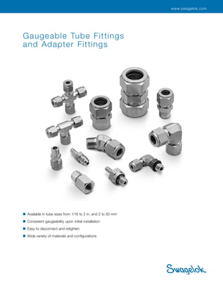
and Adapter Fittings
■ Available in tube sizes from 1/16 to 2 in. and 2 to 50 mm
■ Consistent gaugeability upon initial installation
■ Easy to disconnect and retighten
■ Wide variety of materials and configurations
2. Gaugeable Tube Fittings and Adapter Fittings 2
Features
■ Live-loaded, two-ferrule design.
■ Easy to install.
■ No torque is transmitted to tubing during installation.
■ Swagelok® gap inspection gauge ensures sufficient pull-up upon initial installation.
Two-Ferrule, Mechanical Grip Design
The two ferrules separate sealing and tube gripping
functions; each ferrule is optimized for its function.
The front ferrule creates a seal:
■ against the fitting body
■ on the tubing outside diameter.
As the nut is turned, the back ferrule:
■ axially advances the front ferrule
■ radially applies an effective tube grip.
Advanced-Geometry, Hinging-
Colleting Back Ferrule Design
This design is standard on all 1/4 to 1/2 in. and 6
to 12 mm Swagelok stainless steel tube fittings to
help installers make more consistent, leak-tight tube
connections.
In these sizes, a patented case hardening process
and patented recessed and contoured geometry
provide unique engineering to the Swagelok back
ferrule. The hinging-colleting back ferrule design
expands on the already robust performance of the
traditional ferrule design and provides:
■ excellent gas-tight sealing and tube-gripping action
■ easily achieved proper installation
■ consistent remakes
■ excellent vibration fatigue resistance and tube
support
■ full compatibility with original Swagelok stainless
steel tube fittings of identical sizes.
For additional information, see the 316 Stainless Steel
Swagelok Tube Fittings with Advanced Geometry
Back Ferrules technical report, MS‑06‑16.
Front ferrule
Back ferrule
Tubing
Nut
Fitting body
During assembly of the advanced-geometry design
(above), the front ferrule is driven into the fitting body and
the tubing to create primary seals, while the back ferrule
hinges inward to create a strong grip on the tubing. The
back ferrule geometry allows for an improved engineering
hinging-colleting action that translates axial motion into
radial swaging action on the tube, yet operates with a low
assembly torque requirement.
Hinge point
3. 3 Gaugeable Tube Fittings and Adapter Fittings
Straight Fittings
Unions
Union, 10
Reducing Union,
11
Bulkhead Union
and Bulkhead
Reducing
Union, 12
Male Connectors
NPT, 13
ISO/BSP Tapered
Thread (RT), 14
ISO/BSP Parallel
Thread (RS), 15
ISO/BSP Parallel
Thread (RP), 16
Bulkhead
NPT, 17
SAE/MS Straight
Thread (ST)
and Long SAE/
MS Straight
Thread (ST), 17
O-Seal (SAE/MS
Straight Thread
and NPT), 18
AN and
AN Bulkhead
Fitting, 19
10-32 Thread,
M5 0.8
Thread, and
Metric Thread
(RS), 20
Features, 2
The Swagelok Tube
Fitting Advantage, 6
Materials, 8
Alternative Fuels-Type
Approval, 8
Thread Specifications, 8
O-Rings, 8
Cleaning and
Packaging, 8
Metric Swagelok Tube
Fittings, 9
Pressure Ratings, 9
Ordering Numbers and
Dimensions, 10
Weld Connectors
Tube Socket, 20
Male Pipe, 21
Female Connectors
NPT, 22
ISO/BSP Tapered
Thread (RT), ISO/
BSP Parallel
Thread (RJ and
RP), 23
ISO/BSP Parallel
Thread (RG,
Gauge), 24
Bulkhead
NPT, 24
Reducers
Reducer, 25
Long Reducer,
26
Bulkhead
Reducer, 26
Port Connectors
Port Connector
and Reducing
Port Connector,
27
Contents
Additional Products
■ For SAF 2507 super duplex
tube fittings, see the
Swagelok Gaugeable SAF
2507™ Super Duplex Tube
Fittings catalog, MS‑01‑174.
■ For alloy 400 tube fittings,
see the Swagelok Gaugeable
Alloy 400/R‑405 Mechanically
Attached Pipe and Tube
Fittings catalog, MS‑02‑332.
■ For PFA tube fittings, see the
Swagelok PFA Tube Fittings
catalog, MS‑01‑05.
■ For medium-pressure tube
fittings, see the Swagelok
Medium-Pressure, Gaugeable
Tube Fittings and Adapter
Fittings catalog, MS-02-335.
■ For heavy-wall tube fittings,
see the Swagelok High-
Pressure Fittings catalog,
MS‑01‑34.
5. Gaugeable Tube Fittings and Adapter Fittings 5
Female
NPT and ISO/BSP
Tapered Thread
(RT), 46
ISO/BSP Parallel
Thread (RP and
RJ), and ISO/BSP
Parallel Thread (RG,
Gauge), 47
AN Thread, 47
Additional Ordering
Information, 48
Replacement Parts
Nuts
Female, 50
Knurled Female, 50
Male, 50
Ferrules
Front, 51
Back, 51
Nut-Ferrule Set and
Package and
Ferrule Set and
Ferrule-Pak™
Package, 52
ISO/BSP Parallel Gaskets
Steel (RS Fitting),
Copper (RP Fitting),
Copper (RG, Gauge
Fitting), and PTFE
(RJ Fitting), 53
O-Rings
Buna N (O-Seal
Straight Threads
and O-Seal Pipe
Threads) and
Fluorocarbon FKM
(ISO/BSP Parallel
Threads and
SAE/MS Straight
Threads), 54
Tools and Accessories
Hydraulic Swaging Units, 55
Preswaging Tools, 57
Wrenches, 58
Gap Inspection
Gauges and Depth
Marking Tools, 60
Bulkhead Retainers,
61
Inserts for Soft
Plastic Tubing, 61
For liquid leak detectors, lubricants,
and sealants, see the Swagelok Leak
Detectors, Lubricants, and Sealants
catalog, MS‑01‑91.
For tube benders, tube preparation
tools, and tube support systems,
see the Swagelok Tubing Tools and
Accessories catalog, MS-01-179.
Gaugeability, 62
Installation Instructions, 62
Bored-Through Fittings
For thermocouples, dip tubes, and
heat exchanger tees, 16
Chromatograph Fittings
See the Swagelok
Gaugeable
Chromatograph and
Column End Fittings
catalog, MS-02-173.
Dielectric Fittings
See the Swagelok
Dielectric
Fittings catalog,
MS‑02‑36‑SCS.
Flanges
For ANSI, DIN, and
JIS flanges, see the
Swagelok Flange
Adapters catalog,
MS-02-200.
VCO® and VCR®
Face Seal Fittings
See the Swagelok
VCR Metal Gasket
Face Seal Fittings
and VCO O-Rings
Face Seal Fittings
catalogs, MS-01-24
and MS-01-28.
Contents
6. 6 Gaugeable Tube Fittings and Adapter Fittings
“Over 10 000 fittings
and not a single leak.”
That is the message one customer
wanted to share, crediting Swagelok
components and tube fittings
along with Swagelok distributor
support, as having played a major
role in completing—and obtaining
independent, third-party certification
for—two 12 000 ton oil rigs.
And that is part of the ongoing story
behind the continuous improvement
efforts that Swagelok has initiated and
sustained since the development and
patent of the original two-ferrule tube
fitting more than 50 years ago.
Today, as everyone is being called on
to “do more with less” and to recognize
value, Swagelok continues to improve
the leak-tight design of the tube
fitting for use in thousands of diverse
applications—including research,
analytical and process instrumentation,
bioprocessing, oil and gas, power,
petrochemical, and semiconductor
industries—and addressing such
critical issues as:
■ leakage
■ vibration (tube grip)
■ thermal shock
■ compliance with industry standards
■ installation
■ corrosion
■ intermix/interchange.
Leakage
Excellent gas-tight sealing and
consistent reassembly help ensure
accurate measurements of process
parameters—air, steam, fuel, and
water—to keep your plant operating
efficiently. Moreover, Swagelok tube
fittings minimize fugitive emissions,
as well as process fluid leakage and
operation costs.
From 1999 through 2004, more than
250 000 fittings in gas service at more
than 400 different process installations
were leak tested with Swagelok Snoop®
liquid leak detector. Contact your
authorized Swagelok sales and service
representative for more information
about Swagelok Energy Emissions
Surveys or to schedule a survey.
Vibration (Tube Grip)
The patented case-hardening process
and back-ferrule geometry provide
excellent vibration fatigue resistance
and tube support—even in harsh
or stressful environments, such as
fuel processing or rotary equipment
applications.
Swagelok has conducted rotary flex
tests, which show that the Swagelok
tube fitting with advanced geometry
hinging-colleting back ferrule isolates
and protects the stress riser that
is generated along the tube during
the gripping part of assembly. The
colleting portion of the back ferrule
allows more material to contact the
tube, for additional support. This
colleting action enhances gripping
performance and provides both direct
and axial support to the gripping
function. This design minimizes the
effects of bending deflection at the
point of grip on the tubing.
Contact your authorized Swagelok
representative for more information
about vibration test reports.
The Swagelok Tube Fitting Advantage
7. Gaugeable Tube Fittings and Adapter Fittings 7
Corrosion
Swagelok tube fittings are available
in a variety of materials, including
controlled-chemistry 316 stainless
steel and many other alloys for
enhanced corrosion resistance in a
variety of applications, including sour
gas and subsea systems.
Swagelok has conducted tests in
accordance with ASTM B117-95 to
evaluate the corrosion resistance of
Swagelok tube fittings.
Contact your authorized Swagelok
representative for more information
about corrosion resistance test reports.
Intermix/Interchange
This practice can be dangerous.
Leak-tight seals that will withstand
high pressure, vibration, vacuum,
and temperature changes depend
on close tolerances and consistent,
exacting quality control in conjunction
with good design principles. The
critical interaction of precision parts is
essential for reliability and safety.
Components of other manufacturers
may look like Swagelok tube fitting
components—but they cannot be
manufactured in accordance with
Swagelok engineering standards, nor
do they benefit from innovations in
design and manufacture defined by 36
active Swagelok tube fitting patents
issued since 1989.
Thermal Shock
The elastic, live-loaded two-ferrule
design compensates for changes in
temperature during system start-up
and shutdown and helps eliminate
leakage related to rapid thermal
expansion or contraction.
Swagelok has conducted tests
that demonstrated the capability of
Swagelok tube fittings to withstand
thermal shock and high temperature.
Contact your authorized Swagelok
representative for more information
about thermal shock test reports.
Compliance with
Industry Standards
Swagelok Company works with
standards organizations around the
world to provide you with products that
address your needs.
See Materials, page 8; Thread
Specifications, page 8; and Pressure
Ratings, page 9ection 09, for more
information about the specifications
to which Swagelok tube fittings are
manufactured.
Contact your authorized Swagelok
representative for more information
about Swagelok tube fitting
certifications.
Installation
The Swagelok tube fitting installation
advantages:
■ Easy to install
■ No torque is transmitted to tubing
during installation
■ Swagelok gap inspection gauge
assures sufficient pull-up upon initial
installation.
Swagelok tube fitting components
provide exceptional dimensional,
metallurgical, and mechanical
uniformity that allow predictable,
repeatable installation.
Swagelok authorized sales and service
centers offer installation training
seminars that provide additional
information on:
■ The requirements for making safe,
leak-tight connections
■ A variety of tools and accessories
designed for use with Swagelok tube
fittings.
8. 8 Gaugeable Tube Fittings and Adapter Fittings
O-Rings
O-seal fittings include a 70 durometer Buna N O-ring.
Other straight-thread fittings with O-rings include a 90
durometer fluorocarbon FKM O-ring. Other O-ring materials
are available upon request. O-rings are coated with a thin
film of silicone-based lubricant. Removal of factory-applied
lubricants may alter performance.
Materials
Pipe Thread Sealants
A thread sealant should always be used when assembling
tapered threads. SWAK® anaerobic pipe thread sealant and
Swagelok PTFE tape are available. For more information,
see the Swagelok Leak Detectors, Lubricants, and Sealants
catalog, MS-01-91.
Cleaning and Packaging
Fitting components are cleaned to remove machine oil, grease,
and loose particles. For more information, see Swagelok
Standard Cleaning and Packaging (SC-10), MS‑06‑62.
Fittings are available individually bagged; add CP to the
ordering number.
Example: SS-200-6CP
On request, fittings can be cleaned and packaged in
accordance with Swagelok Special Cleaning and Packaging
(SC-11), MS‑06‑63, with front ferrules silver plated and
Krytox® 240 AC applied to the internal surface of the nut.
To order, add BQ to the ordering number.
Example: SS-400-1-4BQ
Oxygen Service Hazards
For more information about hazards and risks of oxygen-
enriched systems, see the Swagelok Oxygen System Safety
technical report, MS‑06‑13.
Materials Standards
➀ Straight fittings and tube adapters.
➁ Elbows, crosses, and tees.
➂ All straight fittings and tube adapters and 1/4 and 3/8 in.; 6 and 10 mm
elbows, crosses, and tees.
➃ Elbows, crosses, and tees larger than 3/8 in. and 10 mm.
➄ See the Swagelok PFA Tube Fittings catalog, MS-01-05.
➅ See the Swagelok Gaugeable SAF 2507 Super Duplex Tube Fittings
catalog, MS-01-174.
Material Bar Stock➀ Forgings➁
316 stainless
steel
ASTM A276,
ASME SA479, EN 1.4401
ASTM A182,
ASME SA182, EN 1.4401
Alloy 20 ASTM B473 ASTM B462
Alloy 400 ASTM B164 ASTM B564, ASME SB564
Alloy 600 ASTM B166, ASME SB166 ASTM B564, ASME SB564
Alloy 625 ASTM B446➂ ASTM B564, ASME SB564➃
Alloy 825 ASTM B425 ASTM B564, ASME SB564
Alloy C-276 ASTM B574 ASTM B564
Aluminum ASTM B211 ASTM B247
Brass ASTM B16, ASTM B453 ASTM B283
Carbon steel ASTM A108 —
Nylon ASTM D4066 —
PFA➄ — ASTM D3307 Type I
PTFE ASTM D1710 ASTM D3294
SAF 2507➅ ASTM A479 ASTM A182
Titanium
(grade 4)
ASTM B348 ASTM B381
Thread Specifications
Thread Type (End Connection) Reference Specification
NPT ASME B1.20.1, SAE AS71051
ISO/BSP (parallel)
(Based on DIN 3852)
(Swagelok PR, RP, and RS fittings)
ISO 228, JIS B0202
ISO/BSP (tapered)
(Based on DIN 3852)
(Swagelok RT fittings)
ISO 7, BS EN 10226-1,
JIS B0203
ISO/BSP (gauge)
(Based on EN 837-1 and 837-3)
(Swagelok RG and RJ fittings)
ISO 228, JIS B0202
Unified (SAE)
(Swagelok ST fittings)
ASME B1.1
Additional Processing
Fitting bodies are processed for improved performance, as
listed below. No additional processing is required for alloy 625,
alloy 825, brass, nylon, 316 stainless steel, and PTFE materials.
■ Over 1 in./25 mm fittings are supplied with a package of
fluorinated-base with PTFE and tungsten disulfide lubricant
for use in fitting assembly.
■ Over 1 in./25 mm stainless steel fittings use stainless
steel ferrules with PFA coating. Applications above 450°F
(232°C) require silver-plated front ferrules and uncoated
back ferrules. To order fittings with silver-plated front
ferrules and uncoated back ferrules, add -BM to the fitting
ordering number.
Example: SS-2400-6-BM
■ All carbon steel Swagelok tube fittings are supplied with
316 stainless steel back ferrules.
Fitting Body Material Process
Aluminum Anodized, hydrocarbon film
Alloy 400, alloy 20,
alloy C-276, alloy 600
Hydrocarbon film
Carbon steel (except weld bodies) Zinc plating
Carbon steel (weld bodies)
Hydrocarbon film chemical
conversion coating
Titanium Anodized
Alternative Fuels-Type Approval
Stainless steel Swagelok
tube fittings used with
316 stainless steel and 316 Ti
stainless steel alloy tubing
as shown in the table have been tested to the requirements of
ECE R110, EIHP Draft, and ECE R67.
Tube OD Wall Thickness
3 to 16 mm 0.7 to 2.5 mm
1/8 to 5/8 in. 0.028 to 0.095 in.
9. Gaugeable Tube Fittings and Adapter Fittings 9
O-Seal Pressure Ratings
Stainless steel and carbon steel O-seal fittings up to 1 in. and
25 mm are rated to 3000 psig (206 bar).
Pipe End (NPT and ISO 7)
Pressure Ratings Basis
Pressure ratings for fittings with both tube fitting and pipe
thread ends are determined by the end connection with the
lower pressure rating. The table lists pressure ratings for male
and female tapered pipe thread ends. For female and male
pipe threads to have the same pressure rating in the same
nominal pipe size, the female thread would require a heavier
wall, resulting in a fitting too large and bulky to be practical.
SAE/MS Fittings Pressure Ratings Basis
Pressure ratings are based on SAE J1926/3 at ambient
temperature.
Some fittings with AN, O-seal, and SAE/MS ends may have
lower ratings. For more information, contact your authorized
Swagelok representative.
Pressure Ratings
Swagelok Tube Fitting Pressure Ratings
Swagelok tube fitting ends are rated to the working pressure
of tubing as listed in Swagelok Tubing Data, MS-01-107.
Careful selection of high-quality tubing is important when
installing safe, leak-tight systems.
Allowable Stress
Stress values are based on ASME Code for Pressure Piping
B31.3, Process Piping, at ambient temperature.
Material
Allowable Stress
psi bar
316 SS 20 000 1378
Brass 10 000 689
Steel 20 000 1378
■ To determine pressure ratings in accordance with
ASME B31.1, Power Piping:
■ carbon steel material—multiply by 0.85.
Stainless steel and brass material ratings remain the same.
■ To determine MPa, multiply bar by 0.10.
Pressure Ratings
Ratings are based on ASME Code for Pressure Piping B31.3,
Process Piping, at ambient temperature.
NPT/
ISO
Pipe
Size
in.
316 SS and Carbon Steel Brass
Male Female Male Female
psig bar psig bar psig bar psig bar
1/16 11 000 760 6700 460 5500 380 3300 230
1/8 10 000 690 6500 440 5000 340 3200 220
1/4 8 000 550 6600 450 4000 270 3300 220
3/8 7 800 540 5300 360 3900 270 2600 180
1/2 7 700 530 4900 330 3800 260 2400 160
3/4 7 300 500 4600 320 3600 250 2300 160
1 5 300 370 4400 300 2600 180 2200 150
1 1/4 6 000 410 5000 350 3000 200 2500 170
1 1/2 5 000 340 4600 310 2500 170 2300 150
2 3 900 270 3900 270 1900 130 1900 130
SAE/MS
Thread Size Designator
316 SS and Carbon Steel
Nonpositionable Positionable
psig bar psig bar
5/16-24 2ST
4568 315
4568 3157/16-20 4ST
1/2-20 5ST
9/16-18 6ST
3626 250
3/4-16 8ST
7/8-14 10ST
3626 250 2900 200
1 1/16-12 12ST
1 3/16-12 14ST
2900 200 2320 160
1 5/16-12 16ST
1 5/8-12 20ST
2320 160 1813 125
1 7/8-12 24ST
2 1/2-12 32ST 1813 125 1450 100
Metric Swagelok Tube Fittings
Metric tube fittings have a stepped shoulder on the body hex.
Shaped fittings, such as elbows, crosses, and tees, are
stamped MM for metric tubing and have no step on the forging.
Swagelok
metric
tube end
Swagelok
fractional
tube stub
No shoulderStepped identification
shoulders
Stepped identification
shoulders
Swagelok
metric tube
ends
Positionable, ISO/BSP Parallel Thread (PR)
Pressure Ratings
Pressure ratings are at ambient temperature.
ISO/BSP
Male Pipe
Size
in.
316 SS and
Carbon Steel
psig bar
1/8
4568 3151/4
3/8
1/2
2320 1603/4
1
10. 10 Gaugeable Tube Fittings and Adapter Fittings
Union
D D
A
E
Ordering Numbers and Dimensions
■ See How to Order, below. Minimum order quantities may apply to certain materials and configurations.
■ Dimensions are for reference only and are subject to change. Dimensions are shown with Swagelok nuts finger-tight.
For Swagelok nut dimensions, see page 50.
■ CAD templates are available on www.swagelok.com.
Straight Fittings
Unions
Union (Metric to Fractional)
D Dx
A
E
F flat
Tx
T
➀ Bored through.
Tube
OD
Basic
Ordering
Number
Dimensions
A D E
Dimensions, in.
1/16 -100-6 0.99 0.34 0.05
1/8 -200-6 1.40 0.50 0.09
3/16 -300-6 1.47 0.54 0.12
1/4 -400-6 1.61 0.60 0.19
5/16 -500-6 1.69 0.64 0.25
3/8 -600-6 1.77 0.66 0.28
1/2 -810-6 2.02 0.90 0.41
1/2 -810-6-0030➀ 4.30 —
0.50
5/8 -1010-6 2.05
0.96
3/4 -1210-6 2.11 0.62
7/8 -1410-6 2.17 1.02 0.72
1 -1610-6
2.55 1.23
0.88
1 1/8 -1810-6 0.97
1 1/4 -2000-6 3.63 1.62 1.09
1 1/2 -2400-6 4.25 1.97 1.34
2 -3200-6 5.88 2.66 1.81
Dimensions, mm
2 -2M0-6 35.6
12.9
1.7
3 -3M0-6 35.3
2.4
4 -4M0-6 37.3 13.7
6 -6M0-6 41.0 15.3 4.8
8 -8M0-6 43.2 16.2 6.4
10 -10M0-6 46.2 17.2 7.9
12 -12M0-6 51.2 22.8 9.5
14 -14M0-6
52.0
24.4
11.1
15 -15M0-6 11.9
16 -16M0-6 12.7
18 -18M0-6 53.5 15.1
20 -20M0-6
55.0 26.0
15.9
22 -22M0-6 18.3
25 -25M0-6 65.0 31.3
21.8
28 -28M0-6 85.0 36.6
30 -30M0-6 92.7 39.6 26.2
32 -32M0-6 97.3 42.0 28.6
38 -38M0-6 114 49.4 33.7
50 -50M0-6 146 65.0 45.2
Tube OD
Basic
Ordering
Number
Dimensions
T Tx, in. A D Dx E F
Dimensions, mm
2
1/8
1/4
-2M0-6-2
-2M0-6-4
35.2
38.6
12.9
12.8
15.3
1.7
12
14
3 1/8 -3M0-6-2 35.2 12.9 12.8 2.4 12
4
1/8
1/4
-4M0-6-2
-4M0-6-4
36.5
39.4
13.7
12.8
15.3
2.4
12
14
6
1/16
1/8
1/4
5/16
3/8
-6M0-6-1
-6M0-6-2
-6M0-6-4
-6M0-6-5
-6M0-6-6
34.3
38.5
41.0
42.3
43.2
15.3
8.6
12.8
15.3
16.2
16.8
1.3
2.4
4.8
4.8
4.8
14
14
14
14
16
8
1/4
3/8
-8M0-6-4
-8M0-6-6
42.3
44.3
16.2
15.3
16.9
4.8
6.4
15
16
10
1/8
1/4
5/16
3/8
-10M0-6-2
-10M0-6-4
-10M0-6-5
-10M0-6-6
41.8
44.5
45.1
45.9
17.2
12.8
15.3
16.2
16.9
2.4
4.8
6.4
7.1
18
12
1/4
5/16
3/8
1/2
-12M0-6-4
-12M0-6-5
-12M0-6-6
-12M0-6-8
47.0
47.8
48.4
51.2
22.8
15.3
16.2
16.9
22.8
4.8
6.4
7.1
9.5
22
15 1/2 -15M0-6-8 52.0 24.4 22.8 10.3 24
16 5/8 -16M0-6-10 52.0 24.4 24.4 12.7 24
18 3/4 -18M0-6-12 53.5 24.4 24.4 15.1 27
20
1/2
1
-20M0-6-8
-20M0-6-16
55.0
62.8
26.0
22.8
31.3
10.3
15.9
30
35
25 1 -25M0-6-16 65.0 31.3 31.3 21.8 35
How to Order
Select a basic ordering number. Example -100-6
Add a material designator. Example: SS-100-6
Material Designator Material Designator
316 SS SS Alloy C-276 HC
Aluminum A Brass B
Alloy 20 C20 Carbon steel S
Alloy 400 M Nylon NY
Alloy 600 INC PTFE T
Alloy 625 625 Titanium
(grade 4)
TI
Alloy 825 825
16. 16 Gaugeable Tube Fittings and Adapter Fittings
See page 8 for thread specifications.
ISO/BSP parallel gaskets are available. See page 53.
Male Connectors
ISO/BSP Parallel Thread (RP)
D
A
E
F flat
Bored-Through Fittings for Thermocouples,
Dip Tubes, and Heat Exchanger Tees
Swagelok bored-through male connectors
accommodate thermocouples or dip tubes. Most male
connectors are available as a bored-through fitting,
but male connectors whose pipe thread end is small
relative to the tube fitting end—such as -600-1-2 or
-8M0-1-2RT—cannot be bored through.
Swagelok bored-through reducers and standard
Swagelok tees can be used to create a heat exchanger
tee.
To order bored-through fittings, add BT to the ordering
number.
Example: SS-400-1-4BT
Bored-through fittings have a reduced pressure
rating. Contact your authorized Swagelok
representative for details.
➀ The E dimension is the minimum nominal opening. These fittings may have
a larger opening at the pipe/straight thread end.
➀ The E dimension is the minimum nominal opening. These fittings may have
a larger opening at the pipe/straight thread end.
Tube
OD
ISO
Thread
Size
Basic
Ordering
Number
Dimensions
A D E➀ F
Dimensions, in.
1/8
1/8
1/4
-200-1-2RP
-200-1-4RP
1.31
1.50
0.50 0.09
9/16
3/4
1/4
1/8
1/4
-400-1-2RP
-400-1-4RP
1.40
1.59
0.60
0.16
0.19
9/16
3/4
1/2
3/8
1/2
-810-1-6RP
-810-1-8RP
1.79
1.87
0.90
0.31
0.41
7/8
1 1/16
3/4
1/2
3/4
-1210-1-8RP
-1210-1-12RP
1.92
2.05
0.96
0.47
0.62
1 1/16
1 5/16
1 1 -1610-1-16RP 2.35 1.23 0.78 1 5/8
Tube
OD
ISO
Thread
Size, in.
Basic
Ordering
Number
Dimensions
A D E➀ F
Dimensions, mm
3
1/8
1/4
-3M0-1-2RP
-3M0-1-4RP
33.3
38.1
12.9 2.4
14
19
4 1/8 -4M0-1-2RP 34.0 13.7 2.4 14
6
1/8
1/4
3/8
1/2
-6M0-1-2RP
-6M0-1-4RP
-6M0-1-6RP
-6M0-1-8RP
35.6
40.4
41.2
43.2
15.3
4.0
4.8
4.8
4.8
14
19
22
27
8
1/8
1/4
3/8
1/2
-8M0-1-2RP
-8M0-1-4RP
-8M0-1-6RP
-8M0-1-8RP
36.5
41.3
41.9
44.1
16.2
4.0
5.9
6.4
6.4
15
19
22
27
10
1/4
3/8
1/2
-10M0-1-4RP
-10M0-1-6RP
-10M0-1-8RP
42.2
42.9
45.0
17.2
5.9
7.9
7.9
19
22
27
12
1/4
3/8
1/2
3/4
-12M0-1-4RP
-12M0-1-6RP
-12M0-1-8RP
-12M0-1-12RP
45.4
45.4
47.5
52.1
22.8
5.9
7.9
9.5
9.5
22
22
27
35
15 1/2 -15M0-1-8RP 47.5 24.4 11.9 27
16
3/8
1/2
-16M0-1-6RP
-16M0-1-8RP
45.4
47.5
24.4
7.9
11.9
24
27
18
1/2
3/4
-18M0-1-8RP
-18M0-1-12RP
49.0
52.3
24.4
11.9
15.1
27
35
20
1/2
3/4
-20M0-1-8RP
-20M0-1-12RP
50.5
52.5
26.0
11.9
15.9
30
35
22
3/4
1
-22M0-1-12RP
-22M0-1-16RP
52.8
54.5
26.0
15.9
18.3
35
41
25
3/4
1
-25M0-1-12RP
-25M0-1-16RP
57.8
59.8
31.3
15.9
19.8
35
41
28
1
1 1/4
-28M0-1-16RP
-28M0-1-20RP
69.8
72.9
36.6
19.8
21.8
41
50
30 1 1/4 -30M0-1-20RP 76.8 39.6 26.2 50
32 1 1/4 -32M0-1-20RP 79.2 42.0 28.6 50
38 1 1/2 -38M0-1-24RP 92.1 49.4 31.8 55
Straight Fittings
17. Gaugeable Tube Fittings and Adapter Fittings 17
SAE/MS Straight Thread (ST)
Adapts to SAE J1926/1 and ISO 11926-1
straight thread boss.
Male Connectors Bulkhead NPT
D
A
E
F flat
D
A
E
F flat
O-ring
➀ The E dimension is the minimum nominal opening. These fittings may have a larger opening at the
pipe/straight thread end.
➀ The E dimension is the minimum
nominal opening. These fittings
may have a larger opening at the
pipe/straight thread end.
➀ The E dimension is the minimum nominal opening. These fittings may have
a larger opening at the pipe/straight thread end.
Long SAE/MS Straight Thread
Tube
OD
NPT
Size
in.
Basic
Ordering
Number
Dimensions
A D E➀ F
Panel
Hole
Size
Max
Panel
Thickness
Dimensions, in.
1/8 1/8 -200-11-2 1.83 0.50 0.09 1/2 21/64 0.50
1/4
1/8
1/4
-400-11-2
-400-11-4
1.95
2.13
0.60 0.19 5/8 29/64 0.40
3/8
1/4
3/8
1/2
-600-11-4
-600-11-6
-600-11-8
2.26
2.26
2.51
0.66 0.28
3/4
3/4
7/8
37/64 0.44
1/2
3/8
1/2
-810-11-6
-810-11-8
2.49
2.71
0.90
0.38
0.41
15/16 49/64 0.50
3/4 3/4 -1210-11-12 3.00 0.96 0.62 1 3/16 1 1/64 0.66
1 1 -1610-11-16 3.67 1.23 0.88 1 5/8 1 21/64 0.75
Dimensions, mm
6
1/8
1/4
-6M0-11-2
-6M0-11-4
49.5
53.6
15.3 4.8 16 11.5 10.2
12 1/2 -12M0-11-8 68.8 22.8 9.5 24 19.5 12.7
Tube
OD
SAE/MS
Thread
Size
Basic
Ordering
Number
Dimensions
A D E➀ F
Dimensions, in.
1/8
5/16-24
7/16-20
9/16-18
-200-1-2ST
-200-1-4ST
-200-1-6ST
1.18
1.24
1.31
0.50 0.09
7/16
9/16
11/16
1/4
5/16-24
7/16-20
9/16-18
3/4-16
7/8-14
-400-1-2ST
-400-1-4ST
-400-1-6ST
-400-1-8ST
-400-1-10ST
1.27
1.34
1.40
1.48
1.60
0.60
0.09
0.19
0.19
0.19
0.19
1/2
9/16
11/16
7/8
1
5/16 1/2-20 -500-1-5ST 1.37 0.64 0.25 5/8
3/8
7/16-20
9/16-18
3/4-16
7/8-14
-600-1-4ST
-600-1-6ST
-600-1-8ST
-600-1-10ST
1.40
1.46
1.54
1.66
0.66
0.18
0.28
0.28
0.28
5/8
11/16
7/8
1
1/2
9/16-18
3/4-16
7/8-14
1 1/16-12
-810-1-6ST
-810-1-8ST
-810-1-10ST
-810-1-12ST
1.54
1.65
1.77
1.93
0.90
0.28
0.41
0.41
0.41
13/16
7/8
1
1 1/4
5/8
3/4-16
7/8-14
-1010-1-8ST
-1010-1-10ST
1.65
1.78
0.96
0.42
0.50
15/16
1
3/4
3/4-16
1 1/16-12
1 5/16-12
-1210-1-8ST
-1210-1-12ST
-1210-1-16ST
1.81
1.93
1.96
0.96
0.42
0.62
0.63
1 1/16
1 1/4
1 1/2
7/8 1 3/16-12 -1410-1-14ST 1.93 1.02 0.72 1 3/8
1
1 1/16-12
1 5/16-12
-1610-1-12ST
-1610-1-16ST
2.10
2.14
1.23
0.66
0.88
1 3/8
1 1/2
1 1/4 1 5/8-12 -2000-1-20ST 2.69 1.62 1.09 1 7/8
1 1/2 1 7/8-12 -2400-1-24ST 3.06 1.97 1.34 2 1/8
2 2 1/2-12 -3200-1-32ST 4.00 2.66 1.81 2 3/4
Tube
OD
SAE/MS
Thread
Size
Basic
Ordering
Number
Dimensions
A D E➀ F
Dimensions, mm
6 9/16-18 -6M0-1-6ST 35.6 15.3 4.8 18
10
9/16-18
3/4-16
-10M0-1-6ST
-10M0-1-8ST
37.3
39.4
17.2
7.1
7.9
22
12
7/16-20
9/16-18
3/4-16
-12M0-1-4ST
-12M0-1-6ST
-12M0-1-8ST
40.6
39.9
41.9
22.8
5.2
7.1
9.5
22
➀ The E dimension is the minimum nominal opening. These fittings may have
a larger opening at the pipe/straight thread end.
Tube
OD
SAE/MS
Thread
Size
Basic
Ordering
Number
Dimensions
A D E➀ F
Dimensions, in.
1/4 7/16-20 -400-1L-4ST 2.26 0.60 0.19 9/16
1/2 3/4-16 -810-1L-8ST 3.01 0.90 0.41 7/8
Long SAE/MS Straight Thread (ST)
Straight Fittings
18. 18 Gaugeable Tube Fittings and Adapter Fittings
Mounting Dimensions for O-Seal Fittings
For a raised surface, see Fig. 1. The minimum diameter allows metal-to-metal contact outside of the O-ring sealing
diameter to prevent O-ring extrusion.
For a recessed hole that allows the round shoulder of the O-seal fitting into the recess, see Fig. 2.
For a recessed hole that allows the hex of the O-seal fitting into the recess, see Fig. 3.
1/8 in.
Fig. 3
O-Seal (SAE/MS Straight Thread) O-Seal (NPT)
➀ The E dimension is the minimum nominal opening. These fittings may have
a larger opening at the pipe/straight thread end.
➀ The E dimension is the minimum nominal opening. These fittings may have
a larger opening at the pipe/straight thread end.
D
A
E
F flat
O-ring
D
A
E
F flat
O-ring
Male Connectors
➀ Allow clearance for full thread.
➀
Fig. 1
A
➀
C
E
➀
B
D
Fig. 2
Tube
OD
SAE/MS
Thread
Size
Basic
Ordering
Number
Dimensions
A D E➀ F
Dimensions, in.
1/16 5/16-24 -100-1-OR 1.05 0.34 0.05 9/16
1/8 5/16-24 -200-1-OR 1.29 0.50 0.09 9/16
3/16 3/8-24 -300-1-OR 1.35 0.54 0.12 5/8
1/4 7/16-20 -400-1-OR 1.51 0.60 0.19 3/4
5/16 1/2-20 -500-1-OR 1.60 0.64 0.25 7/8
3/8 9/16-18 -600-1-OR 1.67 0.66 0.28 15/16
1/2 3/4-16 -810-1-OR 1.81 0.90 0.41 1 1/8
3/4 1 1/16-12 -1210-1-OR 2.06 0.96 0.62 1 1/2
1 1 5/16-12 -1610-1-OR 2.29 1.23 0.88 1 3/4
Tube
OD
NPT
Size
Basic
Ordering
Number
Dimensions
A D E➀ F
Dimensions, in.
1/8 1/8 -200-1-2-OR 1.29 0.50 0.09 3/4
1/4
1/8
1/4
-400-1-2-OR
-400-1-4-OR
1.38
1.51
0.60 0.19
3/4
15/16
3/8
1/4
3/8
1/2
-600-1-4-OR
-600-1-6-OR
-600-1-8-OR
1.57
1.63
1.85
0.66 0.28
15/16
1 1/8
1 5/16
1/2 1/2 -810-1-8-OR 1.96 0.90 0.41 1 5/16
SAE/MS
Thread
Size
NPT
Size
A
Min
Dia
B
Min
Dia
C
Min
Dia
D
Max
Depth
E
Max
Depth
Dimensions, in.
5/16-24
— 0.50 0.59 0.66 0.09
0.16
5/16-24 0.22
— 1/8 0.69 0.78 0.88 0.16 0.28
3/8-24 — 0.56 0.66 0.75 0.09 0.22
7/16-20 —
0.69 0.78 0.88
0.16
0.28
— 1/8
— 1/4 0.87 0.97 1.09
0.31
1/2-20 — 0.75 0.91 1.03
9/16-18 — 0.81
0.97 1.09
— 1/4 0.87
— 3/8 1.00 1.16 1.31 0.34
— 1/2 1.22 1.34 1.53 0.22 0.44
3/4-16 — 1.00 1.16 1.31 0.16 0.34
— 1/2 1.22 1.34 1.53
0.22
0.44
1 1/16-12 — 1.41 1.53 1.75 0.50
1 5/16-12 — 1.69 1.78 2.03 0.56
Straight Fittings
19. Gaugeable Tube Fittings and Adapter Fittings 19
Male Connectors
➀ The E dimension is the minimum nominal opening. These fittings may have a larger opening at the
pipe/straight thread end.
AN Bulkhead Fitting
AN Fitting
D
A
E
S
F flat F flat
D
A
E
F flat
37°
37°
S
Tube
OD
AN Tube
Flare
Size
Basic
Ordering
Number
Dimensions
A D E➀ F S
Dimensions, in.
1/16 1/8 -100-6-2AN 1.07 0.34 0.05 7/16 5/16-24UNJF-3
1/8
1/8
1/4
-200-6-2AN
-200-6-4AN
1.27
1.38
0.50
0.06
0.09
7/16
1/2
5/16-24UNJF-3
7/16-20UNJF-3
1/4 1/4 -400-6-4AN 1.48 0.60 0.17 1/2 7/16-20UNJF-3
5/16 5/16 -500-6-5AN 1.51 0.64 0.23 9/16 1/2-20UNJF-3
3/8
1/4
3/8
-600-6-4AN
-600-6-6AN
1.56 0.66
0.17
0.28
5/8
7/16-20UNJF-3
9/16-18UNJF-3
1/2 1/2 -810-6-8AN 1.81 0.90 0.39 13/16 3/4-16UNJF-3
3/4 3/4 -1210-6-12AN 2.10 0.96 0.61 1 1/8 1 1/16-12UNJ-3
1 1 -1610-6-16AN 2.42 1.23 0.84 1 3/8 1 5/16-12UNJ-3
Tube
OD
AN
Tube
Flare
Size
Basic
Ordering
Number
Dimensions
A D E F S
Panel
Hole
Size
Max
Panel
Thickness
Dimensions, in.
1/4 1/4 -400-61-4AN 2.12 0.60 0.17 5/8 7/16-20UNJF-3 29/64 0.40
3/8 3/8 -600-61-6AN 2.25 0.66 0.28 3/4 9/16-18UNJF-3 37/64 0.44
1/2 1/2 -810-61-8AN 2.59 0.90 0.39 15/16 3/4-16UNJF-3 49/64 0.50
3/4 3/4 -1210-61-12AN 3.11 0.96 0.61 1 3/16 1 1/16-12UNJ-3 1 1/64 0.66
1 1 -1610-61-16AN 3.64 1.23 0.84 1 5/8 1 5/16-12UNJ-3 1 21/64 0.75
Straight Fittings
20. 20 Gaugeable Tube Fittings and Adapter Fittings
Weld Connectors Tube Socket Weld
D B
A
J
E
Tube
OD
Socket
Weld
Size
Basic
Ordering
Number
Dimensions
A B D E J
Dimensions, in.
1/8 1/8 -200-6-2W 1.14 0.10 0.50 0.09 0.29
1/4 1/4 -400-6-4W 1.32 0.28 0.60 0.19 0.48
3/8 3/8 -600-6-6W 1.48 0.31 0.66 0.28 0.60
1/2 1/2 -810-6-8W 1.62 0.38 0.90 0.41 0.73
3/4 3/4 -1210-6-12W 1.71 0.44 0.96 0.62 1.04
1 1 -1610-6-16W 2.07 0.62 1.23 0.88 1.36
10-32 ThreadMale Connectors
D
A
E
F flat
Tube
OD
Basic
Ordering
Number
Dimensions
A D E➀ F
Dimensions, in.
1/8 -200-1-0157 0.95 0.50
0.09
7/16
1/4 -400-1-0256 1.08 0.60 9/16
➀ The E dimension is the minimum nominal opening. These fittings
may have a larger opening at the pipe/straight thread end.
Gasket
M5 3 0.8 Thread
Tube
OD
Basic
Ordering
Number
Dimensions
A D E➀ F
Dimensions, mm
6 -6M0-1-0046 29.2 15.3 2.0 14
D
A
E
F flat
➀ The E dimension is the minimum nominal opening. These fittings
may have a larger opening at the pipe/straight thread end.
Metric Thread (RS)
E
E
F flat
Tube
OD
Basic
Ordering
Number
Dimensions
A D E➀ F
Dimensions, mm
6
-6M0-1-M10X1.0RS
-6M0-1-M12X1.0RS
36.3
40.4
15.3
3.2
4.8
14
12 -12M0-1-M16X1.5RS 45.5 22.8 9.5 22
➀ The E dimension is the minimum nominal opening. These fittings may
have a larger opening at the pipe/straight thread end.
A
D
Straight Fittings
21. Gaugeable Tube Fittings and Adapter Fittings 21
SWAGELOK MALE PIPE WELD CONNECTOR CUTAWAY-MS-01-140 C-PH-0364-DIM
Weld Connectors
D
A
E J
F flat
37.5°
Male Pipe Weld (Fractional)
➀ The E dimension is the minimum nominal opening. These fittings may have a larger
opening at the weld end. Wall thickness at the weld end is based on schedule 80 pipe.
Tube
OD
Pipe
Weld
Size
Basic
Ordering
Number
Dimensions
A D E➀ F J
Dimensions, in.
1/8 1/8 -200-1-2W 1.20 0.50 0.09 7/16 0.405
3/16 1/8 -300-1-2W 1.23 0.54 0.12 7/16 0.405
1/4
1/8
1/4
-400-1-2W
-400-1-4W
1.29
1.49
0.60 0.19
1/2
9/16
0.405
0.540
5/16
1/8
1/4
-500-1-2W
-500-1-4W
1.34
1.52
0.64
0.21
0.25
9/16
0.405
0.540
3/8
1/4
3/8
1/2
3/4
-600-1-4W
-600-1-6W
-600-1-8W
-600-1-12W
1.57
1.57
1.82
1.88
0.66 0.28
5/8
11/16
7/8
1 1/6
0.540
0.675
0.840
1.050
1/2
3/8
1/2
3/4
1
-810-1-6W
-810-1-8W
-810-1-12W
-810-1-16W
1.71
1.93
1.99
2.25
0.90 0.41
13/16
7/8
1 1/16
1 3/8
0.675
0.840
1.050
1.315
5/8 1/2 -1010-1-8W 1.93 0.96 0.50 15/16 0.840
3/4
1/2
3/4
-1210-1-8W
-1210-1-12W
1.99 0.96
0.55
0.62
1 1/16
0.840
1.050
1 1 -1610-1-16W 2.45 1.23 0.88 1 3/8 1.315
1 1/4 1 1/4 -2000-1-20W 3.04 1.62 1.09 1 3/4 1.660
1 1/2 1 1/2 -2400-1-24W 3.50 1.97 1.34 2 1/8 1.900
2 2 -3200-1-32W 4.47 2.66 1.81 2 3/4 2.375
Male Pipe Weld (Metric to Fractional)
➀ The E dimension is the minimum nominal opening. These fittings may have a larger opening at the
weld end. Wall thickness at the weld end is based on schedule 80 pipe.
➁ This dimension is for steel and aluminum fittings.
Tube
OD
Pipe
Weld
Size
in.
Basic
Ordering
Number
Dimensions
A D E➀ F F, in.➁ J
Dimensions, mm
3 1/8 -3M0-1-2W 30.5 12.9 2.4 12 1/2 10.3
4 1/8 -4M0-1-2W 31.2 13.7 2.4 12 1/2 10.3
6
1/8
1/4
-6M0-1-2W
-6M0-1-4W
32.8
37.9
15.3 4.8 14
1/2
9/16
10.3
13.7
8
1/8
1/4
1/2
-8M0-1-2W
-8M0-1-4W
-8M0-1-8W
34.2
38.7
45.6
16.2
5.4
6.4
6.4
15
15
22
9/16
9/16
7/8
10.3
13.7
21.3
10
1/4
3/8
1/2
-10M0-1-4W
-10M0-1-6W
-10M0-1-8W
40.9
40.9
46.5
17.2
7.5
7.9
7.9
18
18
22
11/16
11/16
7/8
13.7
17.1
21.3
12
1/4
3/8
1/2
3/4
-12M0-1-4W
-12M0-1-6W
-12M0-1-8W
-12M0-1-12W
43.4
43.4
49.0
50.5
22.8
7.5
9.5
9.5
9.5
22
22
22
27
13/16
13/16
7/8
1 1/16
13.7
17.1
21.3
26.7
14 3/8 -14M0-1-6W 44.1 24.4 10.7 24 15/16 17.1
15 1/2 -15M0-1-8W 49.0 24.4 11.9 24 15/16 21.3
16 1/2 -16M0-1-8W 49.0 24.4 12.7 24 15/16 21.3
18 1/2 -18M0-1-8W 50.5 24.4 13.9 27 1 1/16 21.3
30 1 1/4 -30M0-1-20W 77.2 39.6 26.2 46 46 mm 42.2
32 1 1/4 -32M0-1-20W 79.6 42.0 28.6 46 46 mm 42.2
38 1 1/2 -38M0-1-24W 91.6 49.4 33.7 55 55 mm 48.3
Straight Fittings
26. 26 Gaugeable Tube Fittings and Adapter Fittings
Reducers
A
D E
T Tx
F flat
A
D E
T Tx
F flat
Reducer (Metric to Fractional) Reducer (Fractional to Metric)
Tube OD
Basic
Ordering
Number
Dimensions
T Tx, mm A D E F
Dimensions, in.
1/8 6 -200-R-6M 1.42 0.50 0.09 7/16
Tube OD
Basic
Ordering
Number
Dimensions
T Tx, in. A D E F
Dimensions, mm
2 1/8 -2M0-R-2 33.5 12.9 1.7 12
3
1/8
1/4
-3M0-R-2
-3M0-R-4
33.5
36.1
12.9
2.0
2.4
12
4 1/4 -4M0-R-4 37.1 13.7 2.4 12
6
1/8
1/4
5/16
3/8
1/2
-6M0-R-2
-6M0-R-4
-6M0-R-5
-6M0-R-6
-6M0-R-8
36.9
39.2
39.9
40.7
46.3
15.3
2.0
4.4
4.8
4.8
4.8
14
8
1/4
3/8
1/2
-8M0-R-4
-8M0-R-6
-8M0-R-8
40.3
42.0
47.6
16.2
4.4
6.4
6.4
15
10
3/8
1/2
-10M0-R-6
-10M0-R-8
44.2
49.8
17.2
6.8
7.9
18
12
1/2
3/4
-12M0-R-8
-12M0-R-12
52.3
53.8
22.8
9.3
9.5
22
18
3/4
1
-18M0-R-12
-18M0-R-16
56.1
62.4
24.4
14.7
15.1
27
25 1 -25M0-R-16 69.5 31.3 20.2 35
Long Reducer
Use only long reducers in female Swagelok end connections.A
D
ET
F flat
Tx
Tube OD
Basic
Ordering
Number
Dimensions
T Tx A D E F
Dimensions, in.
3/8 1/2 -600-RF-8 2.57 0.66 0.25 5/8
Bulkhead Reducer
A
D
E
F flat F flat
Tube
OD
Basic
Ordering
Number
Dimensions
A D E F
Panel
Hole
Size
Max
Panel
Thickness
Dimensions, in.
1/8 -200-R1-2 1.95 0.50 0.08 1/2 21/64 0.50
1/4 -400-R1-4 2.20 0.60 0.17 5/8 29/64 0.40
3/8 -600-R1-6 2.41 0.66 0.27 3/4 37/64 0.44
1/2 -810-R1-8 2.87 0.90 0.37 15/16 49/64 0.50
5/8 -1010-R1-10 2.96 0.96 0.47 1 1/16 57/64 0.50
3/4 -1210-R1-12 3.21 0.96 0.58 1 3/16 1 1/64 0.66
1 -1610-R1-16 3.95 1.23 0.80 1 5/8 1 21/64 0.75
Straight Fittings
27. Gaugeable Tube Fittings and Adapter Fittings 27
Port Connectors Port Connector
H
E
H
E
➀ Furnished with nuts and preswaged ferrules.
➀ Furnished with nuts and preswaged ferrules.
1 in./25 mm
and under
Over 1 in./25mm
Tube
OD
Basic
Ordering
Number
Dimensions
E H
Dimensions, in.
1/16 -101-PC 0.03 0.54
1/8 -201-PC 0.08 0.88
1/4 -401-PC 0.17 0.98
5/16 -501-PC 0.22 1.02
3/8 -601-PC 0.27 1.05
1/2 -811-PC 0.37 1.43
5/8 -1011-PC 0.47 1.49
3/4 -1211-PC 0.58 1.49
1 -1611-PC 0.80 1.94
1 1/4 -2000-PC➀ 1.02 2.72
1 1/2 -2400-PC➀ 1.25 3.31
2 -3200-PC➀ 1.72 4.56
Tube
OD
Basic
Ordering
Number
Dimensions
E H
Dimensions, mm
3 -3M1-PC 1.9 22.2
6 -6M1-PC 4.1 25.0
8 -8M1-PC 5.6 26.0
10 -10M1-PC 7.1 27.1
12 -12M1-PC 8.8 36.2
15 -15M1-PC 11.2 37.8
16 -16M1-PC 12.0 37.8
18 -18M1-PC 13.9 37.8
20 -20M1-PC 15.5 39.4
25 -25M1-PC 19.9 49.3
28 -28M0-PC➀ 22.5 63.5
30 -30M0-PC➀ 24.3 67.6
32 -32M0-PC➀ 26.5 69.7
38 -38M0-PC➀ 31.6 81.9
Reducing Port Connector
H
T TxE
Tube OD
Basic
Ordering
Number
Dimensions
T Tx E H
Dimensions, in.
1/8 1/16 -201-PC-1 0.03 0.72
1/4
1/16
1/8
-401-PC-1
-401-PC-2
0.03
0.08
0.75
0.90
3/8
1/8
1/4
-601-PC-2
-601-PC-4
0.08
0.17
0.92
1.00
1/2
1/4
3/8
-811-PC-4
-811-PC-6
0.17
0.27
1.17
1.21
3/4 1/2 -1211-PC-8 0.37 1.49
1
1/2
3/4
-1611-PC-8
-1611-PC-12
0.37
0.58
1.69
1.72
Tube OD
Basic
Ordering
Number
Dimensions
T Tx E H
Dimensions, mm
6 3 -6M1-PC-3M 1.9 22.9
8 6 -8M1-PC-6M 4.1 25.4
10
6
8
-10M1-PC-6M
-10M1-PC-8M
4.1
5.6
25.8
26.3
12
6
8
10
-12M1-PC-6M
-12M1-PC-8M
-12M1-PC-10M
4.1
5.6
7.1
29.6
30.1
30.6
16 12 -16M1-PC-12M 8.8 37.5
28 25 -28M1-PC-25M 19.8 56.5
32 25 -32M1-PC-25M 19.8 60.3
38 25 -38M1-PC-25M 19.8 65.8
Straight Fittings
28. 28 Gaugeable Tube Fittings and Adapter Fittings
Caps and Plugs
Cap Plug
A
D
Tube
OD
Basic
Ordering
Number A D
Dimensions, in.
1/16 -100-C 0.59 0.34
1/8 -200-C 0.79 0.50
3/16 -300-C 0.84 0.54
1/4 -400-C 0.92 0.60
5/16 -500-C 0.96 0.64
3/8 -600-C 1.01 0.66
1/2 -810-C 1.21 0.90
5/8 -1010-C 1.24 0.96
3/4 -1210-C 1.27 0.96
7/8 -1410-C 1.37 1.02
1 -1610-C 1.61 1.23
1 1/8 -1810-C 1.61 1.23
1 1/4 -2000-C 2.10 1.62
1 1/2 -2400-C 2.54 1.97
2 -3200-C 3.41 2.66
Tube
OD
Basic
Ordering
Number A D
Dimensions, mm
2 -2M0-C 20.1 12.9
3 -3M0-C 20.1 12.9
4 -4M0-C 21.3 13.7
6 -6M0-C 23.1 15.3
8 -8M0-C 24.5 16.2
10 -10M0-C 26.6 17.2
12 -12M0-C 30.6 22.8
14 -14M0-C 31.4 24.4
15 -15M0-C 31.4 24.4
16 -16M0-C 31.4 24.4
18 -18M0-C 32.2 24.4
20 -20M0-C 34.8 26.0
22 -22M0-C 34.8 26.0
25 -25M0-C 41.0 31.3
28 -28M0-C 48.5 36.6
30 -30M0-C 53.4 39.6
32 -32M0-C 55.8 42.0
38 -38M0-C 65.4 49.4
Tube
OD
Basic
Ordering
Number
Dimensions, in.
1/16 -100-P
1/8 -200-P
3/16 -300-P
1/4 -400-P
5/16 -500-P
3/8 -600-P
1/2 -810-P
5/8 -1010-P
3/4 -1210-P
7/8 -1410-P
1 -1610-P
1 1/4 -2000-P
1 1/2 -2400-P
2 -3200-P
Tube
OD
Basic
Ordering
Number
Dimensions, mm
2 -2M0-P
3 -3M0-P
4 -4M0-P
6 -6M0-P
8 -8M0-P
10 -10M0-P
12 -12M0-P
15 -15M0-P
16 -16M0-P
18 -18M0-P
20 -20M0-P
22 -22M0-P
25 -25M0-P
28 -28M0-P
30 -30M0-P
32 -32M0-P
38 -38M0-P
40 mesh 300 series
stainless steel
wire screen assembly
Vent Protectors Mud Dauber
Swagelok vent protectors, more commonly
known as mud dauber fittings, protect open
ends of instruments, tubing, outlet vents, and
bleed-off lines.
The mesh wire screen prevents foreign objects,
such as mud dauber insects, from entering and
clogging various systems and causing damage.
Vent protectors are available in stainless steel
and brass. To order brass, replace SS in the
ordering number with B.
Example: B-MD-2
40 mesh
wire
screen
A
E
F flat
NPT
Size
Ordering
Number A E F
Dimensions, in.
1/8 SS-MD-2 0.56 0.19 1/2
1/4 SS-MD-4 0.78 0.28 9/16
3/8 SS-MD-6 0.81 0.41 11/16
1/2 SS-MD-8 1.03 0.50 7/8
3/4 SS-MD-12 1.06 0.72 1 1/16
Straight Fittings
31. Gaugeable Tube Fittings and Adapter Fittings 31
See page 8 for thread specifications.
Male
ISO/BSP Tapered Thread (RT)
D
A
E
F flat
➀ The E dimension is the minimum nominal opening. These fittings may have
a larger opening at the pipe/straight thread end.
➀ The E dimension is the minimum nominal opening. These fittings may have
a larger opening at the pipe/straight thread end.
Reducing
Tube
OD
ISO
Thread
Size
Basic
Ordering
Number
Dimensions
A D E➀ F
Dimensions, in.
1/8
1/8
1/4
-200-2-2RT
-200-2-4RT
0.83
0.97
0.50 0.09
7/16
1/2
1/4
1/8
1/4
3/8
1/2
-400-2-2RT
-400-2-4RT
-400-2-6RT
-400-2-8RT
1.06
1.06
1.17
1.25
0.60 0.19
1/2
1/2
11/16
13/16
5/16 1/4 -500-2-4RT 1.13 0.64 0.25 9/16
3/8
1/8
1/4
3/8
-600-2-2RT
-600-2-4RT
-600-2-6RT
1.20
1.20
1.23
0.66 0.28
5/8
5/8
11/16
1/2
1/4
3/8
1/2
-810-2-4RT
-810-2-6RT
-810-2-8RT
1.42 0.90
0.28
0.38
0.41
13/16
3/4 1/2 -1210-2-8RT 1.57 0.96 0.47 1 3/8
1 1 -1610-2-16RT 1.93 1.23 0.88 1 3/8
Tube
OD
ISO
Thread
Size
in.
Basic
Ordering
Number
Dimensions
A D E➀ F
Dimensions, mm
3
1/8
1/4
-3M0-2-2RT
-3M0-2-4RT
23.6
24.6
12.9 2.4
7/16
1/2
4
1/8
1/4
-4M0-2-2RT
-4M0-2-4RT
25.4 13.7 2.4 1/2
6
1/8
1/4
3/8
1/2
-6M0-2-2RT
-6M0-2-4RT
-6M0-2-6RT
-6M0-2-8RT
27.0
27.0
29.8
31.8
15.3 4.8
1/2
1/2
11/16
13/16
8
1/8
1/4
3/8
1/2
-8M0-2-2RT
-8M0-2-4RT
-8M0-2-6RT
-8M0-2-8RT
28.8
28.8
30.6
32.6
16.2
4.8
6.4
6.4
6.4
9/16
9/16
11/16
13/16
10
1/4
3/8
1/2
-10M0-2-4RT
-10M0-2-6RT
-10M0-2-8RT
31.5
31.5
33.5
17.2
7.1
7.9
7.9
11/16
11/16
13/16
12
1/8
1/4
3/8
1/2
3/4
-12M0-2-2RT
-12M0-2-4RT
-12M0-2-6RT
-12M0-2-8RT
-12M0-2-12RT
36.0
36.0
36.0
36.0
39.8
22.8
4.8
7.1
9.5
9.5
9.5
13/16
13/16
13/16
13/16
1 1/16
14 1/2 -14M0-2-8RT 38.1 24.4 11.1 15/16
15 1/2 -15M0-2-8RT 38.1 24.4 11.9 15/16
16
3/8
1/2
-16M0-2-6RT
-16M0-2-8RT
38.0 24.4
9.5
11.9
15/16
18
1/2
3/4
-18M0-2-8RT
-18M0-2-12RT
39.8 24.4
11.9
15.1
1 1/16
20
1/2
3/4
-20M0-2-8RT
-20M0-2-12RT
44.6 26.0
11.9
15.9
1 3/8
22
3/4
1
-22M0-2-12RT
-22M0-2-16RT
44.6 26.0
15.9
18.3
1 3/8
25
3/4
1
-25M0-2-12RT
-25M0-2-16RT
49.1 31.3
15.9
21.8
1 3/8
28 1 -28M0-2-16RT 64.0 36.6 21.8 41 mm
Tube OD
Basic
Ordering
Number
Dimensions
T Tx A D E F, in.
Dimensions, mm
6 6 -6M0-2R-6M 27.0 15.3 4.6 1/2
12 12 -12M0-2R-12M 38.1 22.8 8.8 15/16
90° Elbows
E
F flat
D
A
Tx
T
32. 32 Gaugeable Tube Fittings and Adapter Fittings
Male Positionable, ISO/BSP Parallel Thread (PR)
O-ring
D
A
E
F flat
Fx flat
➀ The E dimension is the minimum nominal opening. These fittings may have a larger opening at the
pipe/straight thread end.
Tube
OD
ISO
Thread
Size
in.
Basic
Ordering
Number
Dimensions
A D E➀ F, in. Fx, in. U
Dimensions, in.
1/4
1/8
1/4
-400-2-2PR
-400-2-4PR
1.06
1.14
0.60
0.16
0.19
1/2
5/8
9/16
3/4
0.60
0.80
3/8
1/4
3/8
-600-2-4PR
-600-2-6PR
1.20
1.31
0.66
0.23
0.28
5/8
13/16
3/4
7/8
0.80
0.96
1/2
1/4
3/8
1/2
-810-2-4PR
-810-2-6PR
-810-2-8PR
1.42
1.42
1.50
0.90
0.23
0.31
0.41
13/16
13/16
15/16
3/4
7/8
1 1/16
0.80
0.96
1.16
5/8 1/2 -1010-2-8PR 1.50 0.96 0.47 15/16 1 1/16 1.16
3/4
1/2
3/4
-1210-2-8PR
-1210-2-12PR
1.57 0.96
0.47
0.62
1 1/16
1 1/16
1 3/8
1.16
1.43
1
3/4
1
-1610-2-12PR
-1610-2-16PR
1.93 1.23
0.62
0.78
1 3/8
1 3/8
1 5/8
1.43
1.82
Dimensions, mm
6
1/8
1/4
-6M0-2-2PR
-6M0-2-4PR
27.0
29.0
15.3
4.0
4.8
1/2
5/8
9/16
3/4
15.2
20.3
8
1/8
1/4
-8M0-2-2PR
-8M0-2-4PR
28.8
29.9
16.2
4.0
5.9
9/16
5/8
9/16
3/4
15.2
20.3
10
1/4
3/8
-10M0-2-4PR
-10M0-2-6PR
33.5 17.2
5.9
7.9
13/16
3/4
7/8
20.3
24.4
12
1/4
3/8
1/2
3/4
-12M0-2-4PR
-12M0-2-6PR
-12M0-2-8PR
-12M0-2-12PR
36.0
36.0
38.0
39.8
22.8
5.9
7.9
9.5
9.5
13/16
13/16
15/16
1 1/16
3/4
7/8
1 1/16
1 3/8
20.3
24.4
29.5
36.3
Positionable, SAE/MS Straight Thread (ST)
O-ring
U
washer OD
SAE/MS positionable fittings are available in
carbon steel and stainless steel only.
Adapts to SAE J1926/1 and ISO 11926‑1
straight thread boss.
D
A
E
F flat
Fx flat
➀ The E dimension is the minimum nominal opening. These fittings may have a larger opening at the
pipe/straight thread end.
Tube
OD
SAE/MS
Thread
Size
Basic
Ordering
Number
Dimensions
A D E➀ F, in. Fx, in. U
Dimensions, in.
1/4
7/16-20
9/16-18
-400-2-4ST
-400-2-6ST
1.12
1.20
0.60 0.19
1/2
5/8
9/16
11/16
0.65
0.79
5/16 1/2-20 -500-2-5ST 1.19 0.64 0.23 9/16 5/8 0.72
3/8
7/16-20
9/16-18
3/4-16
-600-2-4ST
-600-2-6ST
-600-2-8ST
1.26
1.26
1.37
0.66
0.20
0.28
0.28
5/8
5/8
13/16
9/16
11/16
7/8
0.65
0.79
1.01
1/2
9/16-18
3/4-16
-810-2-6ST
-810-2-8ST
1.48 0.90
0.28
0.41
13/16
11/16
7/8
0.79
1.01
5/8 7/8-14 -1010-2-10ST 1.56 0.96 0.50 15/16 1 1.16
3/4 1 1/16-12 -1210-2-12ST 1.63 0.96 0.62 1 1/16 1 1/4 1.44
7/8 1 3/16-12 -1410-2-14ST 1.70 1.02 0.72 1 3/16 1 3/8 1.59
1 1 5/16-12 -1610-2-16ST 1.99 1.23 0.88 1 3/8 1 1/2 1.73
1 1/4 1 5/8-12 -2000-2-20ST 2.67 1.62 1.09 1 11/16 1 7/8 2.16
1 1/2 1 7/8-12 -2400-2-24ST 3.07 1.97 1.34 2 2 1/8 2.45
2 2 1/2-12 -3200-2-32ST 4.22 2.66 1.81 2 3/4 2 3/4 3.16
U
retainer OD
90° Elbows
33. Gaugeable Tube Fittings and Adapter Fittings 33
NPT
Female
D
A
E
F flat
Male Pipe Weld
D
J
A
E
F flat
37.5°
➀ The E dimension is the minimum nominal opening. These fittings may have a larger
opening at the weld end. Wall thickness at the weld end is based on schedule 80 pipe.
Weld Tube Socket Weld
D
B
A
K
E
F flat Tube
OD
Socket
Weld
Size
Basic
Ordering
Number
Dimensions
A B D E F K
Dimensions, in.
1/4 1/4 -400-9-4W 1.06 0.28 0.60 0.19 1/2 0.50
3/8 3/8 -600-9-6W 1.20 0.31 0.66 0.28 5/8 0.63
1/2 1/2 -810-9-8W 1.42 0.38 0.90 0.41 13/16 0.81
3/4 3/4 -1210-9-12W 1.57 0.44 0.96 0.62 1 1/16 1.06
1 1 -1610-9-16W 1.93 0.62 1.23 0.88 1 3/8 1.38
Tube
OD
Pipe
Weld
Size
Basic
Ordering
Number
Dimensions
A D E➀ F J
Dimensions, in.
1/4
1/8
1/4
-400-2-2W
-400-2-4W
1.06 0.60 0.19 1/2
0.405
0.540
3/8 1/4 -600-2-4W 1.20 0.66 0.28 5/8 0.540
1/2 1/2 -810-2-8W 1.42 0.90 0.41 13/16 0.840
3/4 3/4 -1210-2-12W 1.57 0.96 0.62 1 1/16 1.050
Tube
OD
NPT
Size
Basic
Ordering
Number
Dimensions
A D E F
Dimensions, in.
1/8
1/8
1/4
-200-8-2
-200-8-4
0.97
1.08
0.50 0.09
1/2
11/16
3/16 1/8 -300-8-2 1.00 0.54 0.12 1/2
1/4
1/8
1/4
3/8
1/2
-400-8-2
-400-8-4
-400-8-6
-400-8-8
1.06
1.17
1.25
1.36
0.60 0.19
1/2
11/16
13/16
1
5/16
1/8
1/4
-500-8-2
-500-8-4
1.13
1.20
0.64 0.25
9/16
11/16
3/8
1/8
1/4
3/8
1/2
-600-8-2
-600-8-4
-600-8-6
-600-8-8
1.20
1.23
1.31
1.42
0.66 0.28
5/8
11/16
13/16
1
1/2
1/4
3/8
1/2
-810-8-4
-810-8-6
-810-8-8
1.42
1.42
1.53
0.90 0.41
13/16
13/16
1
5/8
3/8
1/2
-1010-8-6
-1010-8-8
1.50
1.57
0.96 0.50
15/16
1 1/16
3/4
1/2
3/4
-1210-8-8
-1210-8-12
1.57
1.76
0.96 0.62
1 1/16
1 3/8
7/8 3/4 -1410-8-12 1.76 1.02 0.72 1 3/8
1
3/4
1
-1610-8-12
-1610-8-16
1.93
2.11
1.23 0.88
1 3/8
1 11/16
Tube
OD
NPT
Size
in.
Basic
Ordering
Number
Dimensions
A D E F, in.
Dimensions, mm
6
1/8
1/4
1/2
-6M0-8-2
-6M0-8-4
-6M0-8-8
27.0
29.8
34.6
15.3 4.8
1/2
11/16
1
8 1/4 -8M0-8-4 30.6 16.2 6.4 11/16
10
1/8
1/4
-10M0-8-2
-10M0-8-4
31.5
33.5
17.2 7.9
11/16
13/16
12
1/4
1/2
-12M0-8-4
-12M0-8-8
36.0
38.8
22.8 9.5
13/16
1
16 1/2 -16M0-8-8 39.5 24.4 12.7 1 1/16
90° Elbows
34. 34 Gaugeable Tube Fittings and Adapter Fittings
Positionable, SAE/MS Straight Thread (ST)
45° Elbows
Male NPT
➀ The E dimension is the minimum nominal opening. These fittings may
have a larger opening at the pipe/straight thread end.
D
A
E
F flat
D
A
E
F flat
O-ring
➀ The E dimension is the minimum nominal opening. These fittings may have a larger
opening at the pipe/straight thread end.
Tube
OD
NPT
Size
Basic
Ordering
Number
Dimensions
A D E➀ F
Dimensions, in.
1/4
1/8
1/4
-400-5-2
-400-5-4
0.97 0.60 0.19 1/2
3/8
1/8
1/4
3/8
-600-5-2
-600-5-4
-600-5-6
1.10
1.10
1.15
0.66
0.19
0.28
0.28
5/8
5/8
13/16
1/2
3/8
1/2
-810-5-6
-810-5-8
1.26 0.90
0.38
0.41
13/16
3/4 3/4 -1210-5-12 1.33 0.96 0.62 1 1/16
1 1 -1610-5-16 1.59 1.23 0.88 1 3/8
Tube
OD
SAE/MS
Thread
Size
Basic
Ordering
Number
Dimensions
A D E➀ F U
Dimensions, in.
1/4 7/16-20 -400-5-4ST 1.01 0.60 0.19 1/2 0.65
3/8 9/16-18 -600-5-6ST 1.10 0.66 0.28 5/8 0.79
1/2 3/4-16 -810-5-8ST 1.26 0.90 0.41 13/16 1.01
3/4 1 1/16-12 -1210-5-12ST 1.33 0.96 0.62 1 1/16 1.44
1 1 5/16-12 -1610-5-16ST 1.59 1.23 0.88 1 3/8 1.73
SAE/MS positionable fittings are available in
carbon steel and stainless steel only.
Adapts to SAE J1926/1 and ISO 11926‑1
straight thread boss.
U
w
asherO
D
36. 36 Gaugeable Tube Fittings and Adapter Fittings
Reducing Union (Metric)
D
Dx
A
Tx
T
Ax E F flat
Tube OD
Basic
Ordering
Number
Dimensions
T Tx A Ax D Dx E F, in.
Dimensions, mm
3
6
-3M0-3-3M-6M 49.3 26.9 12.9 15.3 2.4 1/2
8 -8M0-3-8M-6M 59.9 29.0 16.2 15.3 4.8 5/8
10 -10M0-3-10M-6M 63.0 29.7 17.2 15.3 4.8 11/16
12 -12M0-3-12M-6M 72.0 31.8 22.8 15.3 4.8 13/16
15
12
-15M0-3-15M-12M 77.7 38.9 24.4 22.8 9.5 1
16 -16M0-3-16M-12M 77.6 38.9 24.4 22.8 9.5 1
18 -18M0-3-18M-12M 79.8 39.9 24.4 22.8 9.5 1 1/16
22 -22M0-3-22M-12M 89.4 44.7 26.0 22.8 9.5 1 3/8
25 -25M0-3-25M-12M 98.0 44.7 31.3 22.8 9.5 1 3/8
Reducing Union
D Dx
A
Ax Ay
Ax
E F flat
TxT
T
Tube OD
Basic
Ordering
Number
Dimensions
T Tx A Ax Ay D Dx E F
Dimensions, in.
3/8 1/4 -600-3-4-6 2.34 1.20 1.14 0.66 0.60 0.19 5/8
D
Dx
A
Ax Ay
Ay
E F flat
TxT
Tx
Tube OD
Basic
Ordering
Number
Dimensions
T Tx A Ax Ay D Dx E F
Dimensions, in.
1/2
3/8
-810-3-6-6 2.73 1.42 1.31 0.90 0.66 0.28 13/16
5/8 -1010-3-6-6 2.95 1.53 1.42 0.96 0.66 0.28 1
3/4 -1210-3-6-6 3.03 1.57 1.46 0.96 0.66 0.28 1 1/16
D
Dx
Dx1
A
Ax Ay
Ay1
E
F flat
TxT
Tx1
Tube OD
Basic
Ordering
Number
Dimensions
T Tx Tx1 A Ax Ay Ay1 D Dx Dx1 E F
Dimensions, in.
5/8 1/2
3/8
-1010-3-8-6 3.06 1.53 1.53 1.42 0.96 0.90
0.66 0.28
1
3/4 1/2 -1210-3-8-6 3.14 1.57 1.57 1.46 0.96 0.90 1 1/16
1 3/4 -1610-3-12-6 3.69 1.93 1.76 1.65 1.23 0.96 1 3/8
Unions
Tees
37. Gaugeable Tube Fittings and Adapter Fittings 37
Male Branch, NPT (TTM)
D
A
H
E
➀ The E dimension is the minimum nominal opening. These fittings may have a larger
opening at the pipe/straight thread end.
Tube
OD
NPT
Size
in.
Basic
Ordering
Number
Dimensions
A D E➀ F, in. H
Dimensions, in.
1/8
1/8
1/4
-200-3TTM
-200-3-4TTM
1.86
1.94
0.50 0.09
7/16
1/2
0.70
0.92
3/16 1/8 -300-3TTM 1.92 0.54 0.12 7/16 0.70
1/4
1/8
1/4
-400-3TTM
-400-3-4TTM
2.12 0.60 0.19 1/2
0.74
0.92
5/16 1/8 -500-3TTM 2.34 0.64 0.19 5/8 0.82
3/8
1/4
3/8
-600-3TTM
-600-3-6TTM
2.40
2.62
0.66 0.28
5/8
13/16
1.00
1.11
1/2
3/8
1/2
-810-3TTM
-810-3-8TTM
2.84 0.90
0.38
0.41
13/16
1.11
1.30
5/8 1/2 -1010-3TTM 3.06 0.96 0.47 1 1.41
3/4 3/4 -1210-3TTM 3.14 0.96 0.62 1 1/16 1.45
Dimensions, mm
6
1/8
1/4
-6M0-3TTM
-6M0-3-4TTM
53.9 15.3 4.8 1/2
18.8
23.4
8
1/8
1/4
-8M0-3TTM
-8M0-3-4TTM
59.7 16.2
4.8
6.4
5/8
20.8
25.4
10 1/4 -10M0-3TTM 67.0 17.2 7.1 13/16 26.2
12
3/8
1/4
1/2
-12M0-3TTM
-12M0-3-4TTM
-12M0-3-8TTM
72.0 22.8
9.5
7.1
9.5
13/16
28.2
28.2
33.0
16 1/2 -16M0-3TTM 77.6 24.4 11.9 1 35.8
Run, NPT (TMT)
➀ The E dimension is the minimum nominal opening. These fittings may have a larger
opening at the pipe/straight thread end.
D
A
Ax
E
F flatAx
Tube
OD
NPT
Size
in.
Basic
Ordering
Number
Dimensions
A Ax D E➀ F, in.
Dimensions, in.
1/8
1/8
1/4
-200-3TMT
-200-3-4TMT
1.63
1.89
0.93
0.97
0.50 0.09
7/16
1/2
3/16 1/8 -300-3TMT 1.66 0.96 0.54 0.12 7/16
1/4
1/8
1/4
-400-3TMT
-400-3-4TMT
1.80
1.98
1.06 0.60 0.19 1/2
5/16 1/8 -500-3TMT 1.99 1.17 0.64 0.19 5/8
3/8
1/4
3/8
-600-3TMT
-600-3-6TMT
2.20
2.42
1.20
1.31
0.66 0.28
5/8
13/16
1/2
3/8
1/2
-810-3TMT
-810-3-8TMT
2.53
2.72
1.42 0.90
0.38
0.41
13/16
5/8 1/2 -1010-3TMT 2.88 1.50 0.96 0.47 15/16
3/4 3/4 -1210-3TMT 3.02 1.57 0.96 0.62 1 1/16
Dimensions, mm
6
1/8
1/4
-6M0-3TMT
-6M0-3-4TMT
45.8
50.3
27.0 15.3 4.8 1/2
8 1/4 -8M0-3-4TMT 55.3 29.9 16.2 6.4 5/8
12
1/4
1/2
-12M0-3-4TMT
-12M0-3-8TMT
64.2
69.0
36.0 22.8
7.1
9.5
13/16
16 1/2 -16M0-3TMT 73.1 38.0 24.4 11.9 15/16
Tees
F flat
38. 38 Gaugeable Tube Fittings and Adapter Fittings
U
washer
OD
D
A
Ax
Ax
E F flat Fx flat
O-ring
Positionable Branch, ISO/BSP Parallel Thread (TTR)
Tube ports are identical.
See page 8 for thread specifications.
➀ The E dimension is the minimum nominal opening. These fittings may have a larger opening at the pipe/
straight thread end.
Tube
OD
ISO
Thread
Size
in.
Basic
Ordering
Number
Dimensions
A Ax D E➀ F, in. Fx, in. H U
Dimensions, in.
1/4
1/8
1/4
-400-3TTR
-400-3-4TTR
2.12
2.28
1.06
1.14
0.60
0.16
0.19
1/2
5/8
9/16
3/4
1.04
1.27
0.60
0.80
3/8 1/4 -600-3TTR 2.40 1.20 0.66 0.23 5/8 3/4 1.27 0.80
1/2
3/8
1/2
-810-3TTR
-810-3-8TTR
2.84
3.00
1.42
1.50
0.90
0.31
0.41
13/16
15/16
7/8
1 1/16
1.46
1.71
0.96
1.16
5/8 1/2 -1010-3TTR 3.00 1.50 0.96 0.47 15/16 1 1/16 1.71 1.16
3/4
3/4
1/2
-1210-3TTR
-1210-3-8TTR
3.14 1.57 0.96
0.62
0.47
1 1/16
1 3/8
1 1/16
1.92
1.78
1.43
1.16
1 1 -1610-3TTR 3.86 1.93 1.23 0.78 1 3/8 1 5/8 2.11 1.92
Dimensions, mm
6
1/8
1/4
-6M0-3TTR
-6M0-3-4TTR
53.9
58.0
27.0
29.0
15.3
4.0
4.8
1/2
5/8
9/16
3/4
26.4
32.2
15.2
20.3
8
1/8
1/4
-8M0-3TTR
-8M0-3-4TTR
57.7
59.7
30.0 16.2
4.0
5.9
9/16
5/8
9/16
3/4
28.4
32.3
15.2
20.3
10 1/4 -10M0-3TTR 67.0 33.5 17.2 5.9 13/16 3/4 35.1 20.3
12
3/8
1/2
-12M0-3TTR
-12M0-3-8TTR
72.0
76.1
36.1
38.1
22.8
7.9
9.5
13/16
5/16
7/8
1 1/16
37.1
43.4
24.4
29.5
Male Positionable Branch, SAE/MS Straight Thread (TTS)
➀ The E dimension is the minimum nominal opening. These fittings may have a larger opening at the pipe/
straight thread end.
Tube
OD
SAE/MS
Thread
Size
Basic
Ordering
Number
Dimensions
A Ax D E➀ F Fx H U
Dimensions, in.
1/4 7/16-20 -400-3TTS 2.24 1.12 0.60 0.19 1/2 9/16 1.12 0.65
3/8 9/16-18 -600-3TTS 2.52 1.26 0.66 0.28 5/8 11/16 1.27 0.79
1/2 3/4-16 -810-3TTS 2.96 1.48 0.90 0.41 13/16 7/8 1.49 1.01
3/4 1 1/16-12 -1210-3TTS 3.26 1.63 0.96 0.62 1 1/16 11/4 1.92 1.44
1 1 5/16-12 -1610-3TTS 3.98 1.99 1.23 0.88 1 3/8 1 1/2 2.11 1.73
1 1/4 1 5/8-12 -2000-3TTS 5.34 2.67 1.62 1.09 1 11/16 1 7/8 2.29 2.16
1 1/2 1 7/8-12 -2400-3TTS 6.14 3.07 1.97 1.34 2 2 1/8 2.45 2.45
2 2 1/2-12 -3200-3TTS 8.44 4.22 2.66 1.81 2 3/4 2 3/4 2.77 3.16
SAE/MS positionable fittings are available in
carbon steel and stainless steel only.
Adapts to SAE J1926/1 and ISO 11926‑1
straight thread boss.
Positionable Run, SAE/MS Straight Thread (TST)
➀ The E dimension is the minimum nominal opening. These fittings may have a larger opening at the
pipe/straight thread end.
Tube
OD
SAE/MS
Thread
Size
Basic
Ordering
Number
Dimensions
A Ax D E➀ F Fx U
Dimensions, in.
1/4 7/16-20 -400-3TST 2.24 1.12 0.60 0.19 1/2 9/16 0.65
3/8 9/16-18 -600-3TST 2.53 1.26 0.66 0.28 5/8 11/16 0.79
1/2 3/4-16 -810-3TST 2.97 1.48 0.90 0.41 13/16 7/8 1.01
3/4 1 1/16-12 -1210-3TST 3.55 1.63 0.96 0.62 1 1/16 1 1/4 1.44
1 1 5/16-12 -1610-3TST 4.10 1.99 1.23 0.88 1 3/8 1 1/2 1.73
1 1/4 1 5/8-12 -2000-3TST 4.96 2.67 1.62 1.09 1 11/16 1 7/8 2.16
1 1/2 1 7/8-12 -2400-3TST 5.45 3.07 1.97 1.34 2 2 1/8 2.45
2 2 1/2-12 -3200-3TST 7.04 4.22 2.66 1.81 2 3/4 2 3/4 3.16
SAE/MS positionable fittings are available in
carbon steel and stainless steel only.
Adapts to SAE J1926/1 and ISO 11926‑1
straight thread boss.
Tees
D
A
Ax
H
E F flat
Fx flat
O-ring
U
washer OD
D
A
Ax
H
E F flat
Fx flat
O-ring
U
retainer OD
39. Gaugeable Tube Fittings and Adapter Fittings 39
Positionable Run, ISO/BSP Parallel Thread (TRT)
See page 8 for thread specifications.
Male
➀ The E dimension is the minimum nominal opening. These fittings may have a larger opening at the
pipe/straight thread end.
Tube
OD
ISO
Thread
Size
in.
Basic
Ordering
Number
Dimensions
A Ax D E➀ F, in. Fx, in. U
Dimensions, in.
1/4
1/8
1/4
-400-3TRT
-400-3-4TRT
2.10
2.41
1.06
1.14
0.60
0.16
0.19
1/2
5/8
9/16
3/4
0.60
0.80
3/8 1/4 -600-3TRT 2.47 1.20 0.66 0.23 5/8 3/4 0.80
1/2
3/8
1/2
-810-3TRT
-810-3-8TRT
2.88
3.21
1.42
1.50
0.90
0.31
0.41
13/16
15/16
7/8
1 1/16
0.96
1.16
5/8 1/2 -1010-3TRT 3.21 1.50 0.96 0.47 15/16 1 1/16 1.16
3/4
3/4
1/2
-1210-3TRT
-1210-3-8TRT
3.49
3.35
1.57 0.96
0.62
0.47
1 1/16
1 3/8
1 1/16
1.43
1.16
1 1 -1610-3TRT 4.04 1.93 1.23 0.78 1 3/8 1 5/8 1.82
Dimensions, mm
6
1/8
1/4
-6M0-3TRT
-6M0-3-4TRT
53.4
61.2
27.0
29.0
15.3
4.0
4.8
1/2
5/8
9/16
3/4
15.2
20.3
8
1/8
1/4
-8M0-3TRT
-8M0-3-4TRT
56.3
62.1
28.8
29.9
16.2
4.0
6.4
9/16
5/8
9/16
3/4
15.2
20.3
10 1/4 -10M0-3TRT 68.6 33.5 17.2 5.9 13/16 3/4 20.3
12
3/8
1/2
-12M0-3TRT
-12M0-3-8TRT
73.1
81.5
36.0
38.0
22.8
7.9
9.5
13/16
15/16
7/8
1 1/16
24.4
29.5
Tube ports are identical.
Female Run, NPT (TFT)
D
A
Ax
Ax
E
F flat
Tube
OD
NPT
Size
in.
Basic
Ordering
Number
Dimensions
A Ax D E F, in.
Dimensions, in.
1/8 1/8 -200-3TFT 1.72 0.97 0.50 0.09 1/2
1/4
1/8
1/4
-400-3TFT
-400-3-4TFT
1.81
2.05
1.06
1.17
0.60 0.19
1/2
11/16
3/8 1/4 -600-3TFT 2.11 1.23 0.66 0.28 11/16
1/2
3/8
1/2
-810-3TFT
-810-3-8TFT
2.30
2.69
1.42
1.57
0.90 0.41
13/16
1 1/16
3/4 3/4 -1210-3TFT 3.01 1.76 0.96 0.62 1 3/8
1
3/4
1
-1610-3-12TFT
-1610-3TFT
3.18
3.61
1.93
2.11
1.23 0.88
1 3/8
1 11/16
Dimensions, mm
6
1/8
1/4
-6M0-3TFT
-6M0-3-4TFT
46.0
52.1
27.0
29.8
15.3 4.8
1/2
11/16
8
1/8
1/4
-8M0-3TFT
-8M0-3-4TFT
48.9
53.0
29.9
30.6
16.2 6.4
5/8
11/16
10 1/4 -10M0-3TFT 55.9 33.5 17.2 7.9 13/16
12
1/4
3/8
1/2
-12M0-3-4TFT
-12M0-3TFT
-12M0-3-8TFT
58.4
58.4
68.3
36.0
36.0
39.8
22.8
9.5
10.3
9.5
13/16
13/16
1 1/16
16 1/2 -16M0-3TFT 68.2 39.8 24.4 12.7 1 1/16
U
retainer
OD
D
A
Ax
Ax
E F flat Fx flat
O-ring
Tees
41. Gaugeable Tube Fittings and Adapter Fittings 41
Sanitary Flange Fittings
A
G
F flat
B
C
E minimum opening
Tube
OD
in.
Flange
Size
in.
Ordering
Number
Dimensions, in. (mm)
A B C E F G
1/4
1/2 SS-400-SC-8
1.57 (39.9)
0.37 (9.4)
0.60 (15.2) 0.19 (4.8)
1 0.98 (24.9)
3/4 SS-400-SC-12 0.62 (15.7)
1 SS-400-SC-16 0.87 (22.1)
1 3/8 1.98 (50.3)
1 1/2 SS-400-SC-24 1.37 (34.8)
3/8
1/2 SS-600-SC-8
1.63 (41.4)
0.37 (9.4)
0.66 (16.8) 0.28 (7.1)
1 0.98 (24.9)
3/4 SS-600-SC-12 0.62 (15.7)
1 SS-600-SC-16 0.87 (22.1)
1 3/8 1.98 (50.3)
1 1/2 SS-600-SC-24 1.37 (34.8)
1/2
1/2 SS-810-SC-8
1.74 (44.2)
0.37 (9.4)
0.90 (22.9)
0.37 (9.4)
1 0.98 (24.9)
3/4 SS-810-SC-12 0.62 (15.7)
0.41 (10.4)1 SS-810-SC-16 0.87 (22.1)
1 3/8 1.98 (50.3)
1 1/2 SS-810-SC-24 1.37 (34.8)
1
1 SS-1610-SC-16 1.91 (48.5) 0.87 (22.1)
1.23 (31.2)
0.87 (22.1) 1 3/8 1.98 (50.3)
2 SS-1610-SC-32 2.49 (63.2) 1.37 (34.8) 0.88 (22.4) 2 3/4 2.52 (64.0)
Kwik-Clamp Flange To Swagelok Tube Fitting
42. 42 Gaugeable Tube Fittings and Adapter Fittings
Solve Alignment Problems and Reduce Inventories
Swagelok tube adapters can help eliminate difficult alignment problems and
reduce inventories. Swagelok tube adapters can be used with any Swagelok tube
fittings in this catalog. So, stocking union elbows and union tees in various sizes
and materials—along with commonly used Swagelok adapters—eliminates the
need for stocking special elbows and tees.
Typical Alignment Problem
When installing pipe elbows or tees, it is often difficult to align the fitting with the
desired run.
Swagelok tube adapters are to be used ONLY in Swagelok tube fittings.
Use in fittings made by other manufacturers may result in leakage or
slippage.
Tube Adapters
- BW
1. In this example, the
installation requires
connecting tubing to a
female end connection.
2. When the pipe connection
is tightened, the male elbow
points in the wrong direction
for the desired run. Loosening
the pipe connection could
mean leakage at the pipe
thread.
3. Tighten the pipe
connection of a
Swagelok male adapter
into the female end
connection.
4. Connect a Swagelok union
elbow or tee to the adapter by
tightening the Swagelok tube
fitting with a wrench, while
holding the elbow or tee in the
desired direction. Insert the
tubing into the other end of the
Swagelok elbow or tee and
install the fitting.
Swagelok Solution
By using a Swagelok tube adapter in conjunction with a union elbow or tee, these
difficulties can be avoided.
100
2000
1505
0
10
14
50
43. Gaugeable Tube Fittings and Adapter Fittings 43
➀ The E dimension is the minimum nominal opening. These fittings may
have a larger opening at the pipe/straight thread end.
➁ Furnished with nut and preswaged ferrules.
➀ The E dimension is the minimum nominal opening. These fittings may
have a larger opening at the pipe/straight thread end.
➁ Furnished with nut and preswaged ferrules.
Male
NPT
1 in./25 mm and under
A
E
F flat
Over 1 in./25 mm
A
E
F flat
ISO/BSP Tapered Thread (RT)
Tube
OD
NPT
Size
in.
Basic
Ordering
Number
Dimensions
A E➀ F
Dimensions, in.
1/8
1/8
1/4
-2-TA-1-2
-2-TA-1-4
1.16
1.37
0.08
7/16
9/16
3/16
1/8
1/4
-3-TA-1-2
-3-TA-1-4
1.19
1.40
0.12
7/16
9/16
1/4
1/8
1/4
3/8
1/2
-4-TA-1-2
-4-TA-1-4
-4-TA-1-6
-4-TA-1-8
1.25
1.46
1.49
1.71
0.17
7/16
9/16
11/16
7/8
5/16
1/8
1/4
-5-TA-1-2
-5-TA-1-4
1.29
1.50
0.19
0.22
7/16
9/16
3/8
1/8
1/4
3/8
1/2
-6-TA-1-2
-6-TA-1-4
-6-TA-1-6
-6-TA-1-8
1.32
1.53
1.56
1.78
0.19
0.27
0.27
0.27
7/16
9/16
11/16
7/8
1/2
1/4
3/8
1/2
-8-TA-1-4
-8-TA-1-6
-8-TA-1-8
1.75
1.78
2.00
0.28
0.37
0.37
9/16
11/16
7/8
5/8 1/2 -10-TA-1-8 2.06 0.47 7/8
3/4
1/2
3/4
-12-TA-1-8
-12-TA-1-12
2.06
0.47
0.58
7/8
1 1/16
1
3/4
1
-16-TA-1-12
-16-TA-1-16
2.31
2.60
0.62
0.80
1 1/16
1 3/8
1 1/4 1 1/4 -20-TA-1-20➁ 3.16 1.02 1 3/4
1 1/2 1 1/2 -24-TA-1-24➁ 3.72 1.25 2 1/8
2 2 -32-TA-1-32➁ 4.70 1.72 2 3/4
Dimensions, mm
6
1/8
1/4
-6-MTA-1-2
-6-MTA-1-4
32.8
38.1
4.1
12
14
8
1/4
3/8
-8-MTA-1-4
-8-MTA-1-6
39.1
39.9
5.6
14
19
10
1/4
3/8
1/2
-10-MTA-1-4
-10-MTA-1-6
-10-MTA-1-8
39.9
40.6
46.2
7.1
14
18
22
12
1/4
1/2
-12-MTA-1-4
-12-MTA-1-8
46.5
52.1
7.1
8.8
16
22
28
1
1 1/4
-28-MTA-1-16➁
-28-MTA-1-20➁
74.7
76.2
22.2
22.5
35
46
30
1
1 1/4
-30-MTA-1-16➁
-30-MTA-1-20➁
79.2
80.0
22.2
24.3
41
46
32 1 1/4 -32-MTA-1-20➁ 81.0 26.5 46
38 1 1/2 -38-MTA-1-24➁ 92.2 31.6 55
Tube
OD
ISO
Thread
Size
in.
Basic
Ordering
Number
Dimensions
A E➀ F
Dimensions, in.
1/8
1/8
1/4
-2-TA-1-2RT
-2-TA-1-4RT
1.16
1.37
0.08
7/16
9/16
1/4
1/8
1/4
-4-TA-1-2RT
-4-TA-1-4RT
1.25
1.46
0.17
7/16
9/16
3/8
1/4
3/8
1/2
-6-TA-1-4RT
-6-TA-1-6RT
-6-TA-1-8RT
1.53
1.56
1.78
0.27
9/16
11/16
7/8
1/2
1/4
3/8
1/2
-8-TA-1-4RT
-8-TA-1-6RT
-8-TA-1-8RT
1.75
1.78
2.00
0.28
0.37
0.37
9/16
11/16
7/8
3/4 3/4 -12-TA-1-12RT 2.06 0.58 1 1/16
1 1 -16-TA-1-16RT 2.60 0.80 1 3/8
Dimensions, mm
6
1/8
1/4
-6-MTA-1-2RT
-6-MTA-1-4RT
32.8
38.1
4.1
12
14
8 1/4 -8-MTA-1-4RT 39.1 5.6 14
10
1/4
3/8
-10-MTA-1-4RT
-10-MTA-1-6RT
39.9
40.6
7.1
14
18
12
1/4
3/8
1/2
-12-MTA-1-4RT
-12-MTA-1-6RT
-12-MTA-1-8RT
46.5
46.2
51.8
7.1
8.8
8.8
16
18
22
28
1
1 1/4
-28-MTA-1-16RT➁
-28-MTA-1-20RT➁
74.7
76.2
22.2
22.5
35
46
30 1 1/4 -30-MTA-1-20RT➁ 80.0 24.3 46
32 1 1/4 -32-MTA-1-20RT➁ 81.0 26.5 46
38 1 1/2 -38-MTA-1-24RT➁ 92.2 31.6 55
Tube Adapters
44. 44 Gaugeable Tube Fittings and Adapter Fittings
Male
ISO/BSP Parallel Thread (RS)
1 in./25 mm and under
A
E
Over 1 in./25 mm
A
E
F flat
F flat
ISO/BSP parallel gaskets are available. See page 53.
➀ The E dimension is the minimum nominal opening. These fittings may
have a larger opening at the pipe/straight thread end.
➁ Furnished with nut and preswaged ferrules.
Tube
OD
ISO
Thread
Size
in.
Basic
Ordering
Number
Dimensions
A E➀ F
Dimensions, in.
1/8
1/8
1/4
-2-TA-1-2RS
-2-TA-1-4RS
1.25
1.43
0.08
9/16
3/4
1/4
1/8
1/4
-4-TA-1-2RS
-4-TA-1-4RS
1.35
1.53
0.16
0.17
9/16
3/4
3/8
1/4
3/8
-6-TA-1-4RS
-6-TA-1-6RS
1.59
1.62
0.23
0.27
3/4
7/8
1/2
1/4
3/8
1/2
-8-TA-1-4RS
-8-TA-1-6RS
-8-TA-1-8RS
1.85
1.88
1.96
0.23
0.31
0.37
3/4
7/8
1 1/16
3/4 3/4 -12-TA-1-12RS 2.20 0.58 1 5/16
1 1 -16-TA-1-16RS 2.59 0.80 1 5/8
Dimensions, mm
6
1/8
1/4
-6-MTA-1-2RS
-6-MTA-1-4RS
34.3
38.9
4.0
4.1
14
19
8 1/4 -8-MTA-1-4RS 39.6 5.6 19
10
1/4
3/8
1/2
-10-MTA-1-4RS
-10-MTA-1-6RS
-10-MTA-1-8RS
40.4
41.1
43.2
5.9
7.1
7.1
19
22
27
12
1/4
3/8
1/2
-12-MTA-1-4RS
-12-MTA-1-6RS
-12-MTA-1-8RS
47.0
47.8
49.8
5.9
7.9
8.8
19
22
27
18
1/2
3/4
-18-MTA-1-8RS
-18-MTA-1-12RS
51.3
55.9
11.9
13.9
27
35
28
1
1 1/4
-28-MTA-1-16RS➁
-28-MTA-1-20RS➁
71.9
75.4
19.8
22.5
41
50
30 1 1/4 -30-MTA-1-20RS➁ 79.8 24.3 50
32 1 1/4 -32-MTA-1-20RS➁ 80.8 26.5 50
38 1 1/2 -38-MTA-1-24RS➁ 91.9 31.6 55
ISO/BSP Parallel Thread (RP)
➀ The E dimension is the minimum nominal opening. These fittings may
have a larger opening at the pipe/straight thread end.
➁ Furnished with nut and preswaged ferrules.
Tube
OD
ISO
Thread
Size
in.
Basic
Ordering
Number
Dimensions
A E➀ F
Dimensions, mm
28
1
1 1/4
-28-MTA-1-16RP➁
-28-MTA-1-20RP➁
72.7
77.3
19.8
22.5
41
50
30 1 1/4 -30-MTA-1-20RP➁ 81.1 24.3 50
32 1 1/4 -32-MTA-1-20RP➁ 82.1 26.5 50
38 1 1/2 -38-MTA-1-24RP➁ 94.5 31.8 55
SWAGELOK MALE TUBE ADAPTER ISO PARALLEL THREADS (RP) CUTAWAY-MS-01-140 C-PH-1061A-DIM
A
F flat
E
ISO/BSP parallel gaskets are available. See page 53.
Tube Adapters
45. Gaugeable Tube Fittings and Adapter Fittings 45
Male
O-Seal (SAE/MS Straight Thread)
See page 18 for mounting dimensions.
A
E
F flat
O-ring
AN Thread
➀ The E dimension is the minimum nominal opening. These fittings may have a larger
opening at the pipe/straight thread end.
A
E
F flat
37°
Tube
OD
SAE/MS
Thread
Size
Basic
Ordering
Number
Dimensions
A E F
Dimensions, in.
1/8 5/16-24 -2-TA-1-OR 1.28 0.08 9/16
3/16 3/8-24 -3-TA-1-OR 1.38 0.12 5/8
1/4 7/16-20 -4-TA-1-OR 1.54 0.17 3/4
5/16 1/2-20 -5-TA-1-OR 1.64 0.22 7/8
3/8 9/16-18 -6-TA-1-OR 1.70 0.27 15/16
1/2 3/4-16 -8-TA-1-OR 1.95 0.37 1 1/8
Tube
OD
AN
Tube
Flare
Size
Thread
Size
Basic
Ordering
Number
Dimensions
A E➀ F
Dimensions, in.
1/4 1/4 7/16-20UNJF-3 -4-TA-1-4AN 1.46 0.17 1/2
3/8
1/4
3/8
7/16-20UNJF-3
9/16-18UNJF-3
-6-TA-1-4AN
-6-TA-1-6AN
1.53
1.56
0.17
0.27
1/2
5/8
1/2 1/2 3/4-16UNJF-3 -8-TA-1-8AN 1.91 0.37 13/16
3/4 3/4 1 1/16-12UNJ-3 -12-TA-1-12AN 2.21 0.58 1 1/8
1 1 1 5/16-12UNJ-3 -16-TA-1-16AN 2.58 0.80 1 3/8
SAE/MS Straight Thread (ST)
1 in./25 mm and under
A
E
Over 1 in./25 mm
A
E
F flat
O-ring
O-ring
F flat
Adapts to SAE J1926/1 and ISO 11926-1 straight thread boss.
➀ The E dimension is the minimum nominal opening. These fittings may
have a larger opening at the pipe/straight thread end.
➁ Furnished with nut and preswaged ferrules.
Tube
OD
SAE/MS
Thread
Size
Basic
Ordering
Number
Dimensions
A E➀ F
Dimensions, in.
1/8 5/16-24 -2-TA-1-2ST 1.20 0.08 7/16
1/4 7/16-20 -4-TA-1-4ST 1.39 0.17 9/16
3/8
7/16-20
9/16-18
3/4-16
-6-TA-1-4ST
-6-TA-1-6ST
-6-TA-1-8ST
1.46
1.52
1.60
0.20
0.27
0.27
9/16
11/16
7/8
1/2
9/16-18
3/4-16
-8-TA-1-6ST
-8-TA-1-8ST
1.74
1.82
0.28
0.37
11/16
7/8
5/8 7/8-14 -10-TA-1-10ST 1.94 0.47 1
3/4 1 1/16-12 -12-TA-1-12ST 2.10 0.58 1 1/4
1 1 5/16-12 -16-TA-1-16ST 2.41 0.80 1 1/2
1 1/4 1 5/8-12 -20-TA-1-20ST➁ 2.81 1.02 1 7/8
1 1/2 1 7/8-12 -24-TA-1-24ST➁ 3.28 1.25 2 1/8
2 2 1/2-12 -32-TA-1-32ST➁ 4.23 1.72 2 3/4
Tube Adapters
46. 46 Gaugeable Tube Fittings and Adapter Fittings
Female
NPT ISO/BSP Tapered Thread (RT)
➀ Furnished with nut and preswaged ferrules.
1 in./25 mm and under
A
E
Over 1 in./25 mm
A
E
F flat
F flat
Pipe Weld
A
JE
37.5°
Tube
OD
Pipe
Weld
Size
Basic
Ordering
Number
Dimensions
A E J
Dimensions, in.
1/4 1/4 -4-TA-1-4W 1.14 0.17 0.540
3/8 1/2 -6-TA-1-8W 1.46 0.27 0.840
1/2
1/2
3/4
-8-TA-1-8W
-8-TA-1-12W
1.66
1.68
0.37
0.840
1.050
3/4 3/4 -12-TA-1-12W 1.87 0.58 1.050
Tube
OD
NPT
Size
in.
Basic
Ordering
Number
Dimensions
A E F
Dimensions, in.
1/8
1/8
1/4
-2-TA-7-2
-2-TA-7-4
1.24
1.39
0.08
9/16
3/4
3/16 1/4 -3-TA-7-4 1.41 0.12 3/4
1/4
1/8
1/4
3/8
1/2
-4-TA-7-2
-4-TA-7-4
-4-TA-7-6
-4-TA-7-8
1.30
1.46
1.55
1.79
0.17
9/16
3/4
7/8
1 1/16
5/16 1/4 -5-TA-7-4 1.48 0.22 3/4
3/8
1/8
1/4
3/8
1/2
-6-TA-7-2
-6-TA-7-4
-6-TA-7-6
-6-TA-7-8
1.35
1.50
1.59
1.84
0.27
9/16
3/4
7/8
1 1/16
1/2
1/4
3/8
1/2
-8-TA-7-4
-8-TA-7-6
-8-TA-7-8
1.71
1.79
2.05
0.37
3/4
7/8
1 1/16
5/8 1/2 -10-TA-7-8 2.09 0.47 1 1/16
3/4
1/2
3/4
1
-12-TA-7-8
-12-TA-7-12
-12-TA-7-16
2.08
2.16
2.30
0.58
1 1/16
1 5/16
1 5/8
1
3/4
1
-16-TA-7-12
-16-TA-7-16
2.39
2.53
0.80
1 5/16
1 5/8
1 1/4 1 1/4 -20-TA-7-20➀ 3.06 1.02 2 1/8
1 1/2 1 1/2 -24-TA-7-24➀ 3.50 1.25 2 3/8
2 2 -32-TA-7-32➀ 4.23 1.72 2 7/8
Dimensions, mm
6
1/8
1/4
-6-MTA-7-2
-6-MTA-7-4
32.5
37.1
4.1
14
19
8 1/4 -8-MTA-7-4 37.6 5.6 19
10
1/4
3/8
1/2
-10-MTA-7-4
-10-MTA-7-6
-10-MTA-7-8
38.1
40.1
46.7
7.1
19
22
27
12
1/4
1/2
-12-MTA-7-4
-12-MTA-7-8
43.7
52.3
8.8
19
27
Tube
OD
ISO
Thread
Size
in.
Basic
Ordering
Number
Dimensions
A E F
Dimensions, in.
1/4
1/8
1/4
-4-TA-7-2RT
-4-TA-7-4RT
1.30
1.45
0.17
9/16
3/4
3/8
1/4
3/8
-6-TA-7-4RT
-6-TA-7-6RT
1.50
1.59
0.27
3/4
7/8
1/2
1/4
3/8
1/2
-8-TA-7-4RT
-8-TA-7-6RT
-8-TA-7-8RT
1.71
1.80
2.05
0.37
3/4
7/8
1 1/16
Dimensions, mm
6 1/8 -6-MTA-7-2RT 33.0 4.1 14
8 1/4 -8-MTA-7-4RT 37.6 5.6 19
10 1/4 -10-MTA-7-4RT 38.1 7.1 19
Wall thickness at weld end is based on schedule 80 pipe.
Male
Tube Adapters
47. Gaugeable Tube Fittings and Adapter Fittings 47
Female
ISO/BSP Parallel Thread (RP)
ISO/BSP Parallel Thread (RJ)
ISO/BSP Parallel Thread (RG, Gauge)
AN Thread
74°
ISO/BSP parallel gaskets
and O‑rings are available.
See page 53.
A
E
F flat
A
E
F flat
A
E
F flat
F flat
Tube
OD
ISO
Thread
Size
in.
Basic
Ordering
Number
Dimensions
A E F
Dimensions, in.
1/8 1/8 -2-TA-7-2RP 1.17 0.08 9/16
1/4
1/8
1/4
-4-TA-7-2RP
-4-TA-7-4RP
1.25
1.50
0.17
9/16
3/4
3/8
1/4
3/8
-6-TA-7-4RP
-6-TA-7-6RP
1.55
1.57
0.27
3/4
15/16
1/2
3/8
1/2
-8-TA-7-6RP
-8-TA-7-8RP
1.78
2.02
0.38
15/16
1 1/16
Dimensions, mm
6
1/8
1/4
-6-MTA-7-2RP
-6-MTA-7-4RP
32.0
37.8
4.1
14
19
12 1/2 -12-MTA-7-8RP 49.8 8.8 27
Tube
OD
ISO
Thread
Size
in.
Ordering
Number
Dimensions
A E F
Dimensions, in.
1/4 1/4 SS-4-TA-7-4RJ 1.39 0.17 3/4
3/8 3/8 SS-6-TA-7-6RJ 1.55 0.26 15/16
1/2 1/2 SS-8-TA-7-8RJ 1.94 0.28 1 1/16
Dimensions, mm
6
1/4
3/8
1/2
SS-6-MTA-7-4RJ
SS-6-MTA-7-6RJ
SS-6-MTA-7-8RJ
35.3
38.6
42.9
4.1
19
24
27
8
1/4
3/8
1/2
SS-8-MTA-7-4RJ
SS-8-MTA-7-6RJ
SS-8-MTA-7-8RJ
33.0
39.4
43.7
5.5
5.6
5.6
19
24
27
10
1/4
3/8
1/2
SS-10-MTA-7-4RJ
SS-10-MTA-7-6RJ
SS-10-MTA-7-8RJ
34.5
36.1
41.1
5.5
6.5
7.1
19
24
27
12
1/4
3/8
1/2
SS-12-MTA-7-4RJ
SS-12-MTA-7-6RJ
SS-12-MTA-7-8RJ
40.1
44.7
48.8
5.5
6.5
7.0
19
24
27
Tube
OD
ISO
Thread
Size
in.
Basic
Ordering
Number
Dimensions
A E F
Dimensions, in.
1/4 1/4 -4-TA-7-4RG 1.39 0.17 3/4
3/8 3/8 -6-TA-7-6RG 1.55 0.26 15/16
1/2 1/2 -8-TA-7-8RG 1.80 0.28 1 1/16
Dimensions, mm
6
1/4
3/8
1/2
-6-MTA-7-4RG
-6-MTA-7-6RG
-6-MTA-7-8RG
35.3
38.4
42.9
4.1
19
24
27
8
1/4
3/8
1/2
-8-MTA-7-4RG
-8-MTA-7-6RG
-8-MTA-7-8RG
33.0
38.9
43.7
5.5
5.6
5.6
19
24
27
10
1/4
3/8
1/2
-10-MTA-7-4RG
-10-MTA-7-6RG
-10-MTA-7-8RG
34.5
36.1
41.1
5.5
6.5
7.1
19
24
27
12
1/4
3/8
1/2
-12-MTA-7-4RG
-12-MTA-7-6RG
-12-MTA-7-8RG
40.1
44.7
48.8
5.5
6.5
7.0
19
24
27
16 1/2 -16-MTA-7-8RG 49.0 7.0 27
18 1/2 -18-MTA-7-8RG 49.3 7.0 27
Tube
OD
AN
Tube
Flare
Size
Basic
Ordering
Number F
Dimensions, in.
1/8
1/8
1/4
-200-A-2ANF
-200-A-4ANF
3/8
9/16
1/4 1/4 -400-A-4ANF 9/16
3/8 3/8 -600-A-6ANF 11/16
1/2 1/2 -810-A-8ANF 7/8
3/4 3/4 -1210-A-12ANF 1 1/4
ISO/BSP parallel gaskets
and O‑rings are available.
See page 53.
Tube Adapters
ISO/BSP parallel thread
(RJ) fittings are available in
stainless steel only.
ISO/BSP parallel gaskets
and O‑rings are available.
See page 53.