Single stage bjt amplifier. experiment 6
•Download as DOC, PDF•
9 likes•26,251 views

This document describes the theory and experimental procedure of a single stage BJT amplifier. It discusses the three common configurations of BJT amplifiers: common emitter, common base, and common collector. The experiment aims to differentiate the configurations, measure DC and AC parameters, and observe the voltage gain differences between common emitter and common collector circuits. Key results showed the common emitter configuration amplified the signal as expected, while the common collector configuration did not amplify and had a voltage gain close to unity.

Recommended
More Related Content
What's hot
What's hot (20)
Viewers also liked
Similar to Single stage bjt amplifier. experiment 6
Similar to Single stage bjt amplifier. experiment 6 (20)
Single stage bjt amplifier. experiment 6
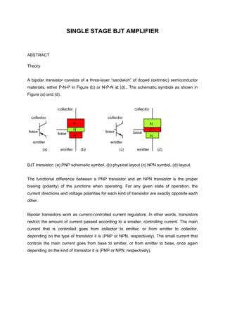
- 1. SINGLE STAGE BJT AMPLIFIER ABSTRACT Theory A bipolar transistor consists of a three-layer “sandwich” of doped (extrinsic) semiconductor materials, either P-N-P in Figure (b) or N-P-N at (d).. The schematic symbols as shown in Figure (a) and (d). BJT transistor: (a) PNP schematic symbol, (b) physical layout (c) NPN symbol, (d) layout. The functional difference between a PNP transistor and an NPN transistor is the proper biasing (polarity) of the junctions when operating. For any given state of operation, the current directions and voltage polarities for each kind of transistor are exactly opposite each other. Bipolar transistors work as current-controlled current regulators. In other words, transistors restrict the amount of current passed according to a smaller, controlling current. The main current that is controlled goes from collector to emitter, or from emitter to collector, depending on the type of transistor it is (PNP or NPN, respectively). The small current that controls the main current goes from base to emitter, or from emitter to base, once again depending on the kind of transistor it is (PNP or NPN, respectively).
- 2. The are three types of configurations: 1) Common Emitter Configuration Here the emitter terminal is common to both the input and output signal. The arrangement is the same for a PNP transistor. Used in this way the transistor has the advantages of a medium input impedance, medium output impedance, high voltage gain and high current gain. 2) Common Base Configuration Here the base is the common terminal. Used frequently for RF applications, this stage has the following properties. Low input impedance, high output impedance, unity (or less) current gain and high voltage gain. 3) Common Collector Configuration This last configuration is also more commonly known as the emitter follower. This is because the input signal applied at the base is follow quite closely at the emitter with a voltage gain close to unity. The properties are a high input impedance, a very low output impedance, a unity voltage gain and a high current gain. This circuit is also used extensively as a buffer converting impedances or for feeding or driving long cables or low impedance loads. Characteristic Common Base Common Emitter Common Collector Voltage Gain,Av High Medium Unity Current Gain,Ai Less than unity Medium High Power Gain Low High Medium Input impedance,Zin Low Medium High Output impedance,Zout High Medium Low The main objectives of this experiment are 1) To differentiate the BJT configuration 2) To measure the dc and ac parameters of BJT
- 3. 3) To observe the differences of voltage gain by common emitter and common collector circuit 4) To observe the waveform differences between the voltage output and voltage input List of equipment was used in this experiment Equiment Component 1) DC Power supply 1) Breadboard 2) Oscilloscope 2) Transistor:BC 109 3) Digital multimeter 3) Resistor:1kΩ,3.3kΩ,27kΩ,120kΩ 4) Function generator 4) Capacitors:10µF,47 µF,22 µF 5) Connecting wires and clippers EXPERIMENT PROCEDURE 1) The Circuit was constructed as shown in Figure 6.2. 2) The Value of VB,VC,VE,VBE and VCE was recorded and measured in Table 6.2.The Amplifier was designed to function with the following bias:VBE~0.7V and VC 0.5Vcc. 3) A 1kHz,20mVp-p signal was applied from signal generator to the amplifier and the input and output signals on the oscilloscope was observed.The input voltage,Vin was slowly increased until the output voltage achieves maximum value without distortion.The input and output waveform was drawed to identify of configuration being used,in Figure 6.4(a) and Figure 6.4(b) respectively. 4) The voltage output,Vo was measured and the voltage gain,Av was calculated by using Equation 6.1 (Equation 6.1) 5) Step 3 and 4 for the circuit shown in Figure 6.3 was repeated,The input and output waveform was drawed in Figure 6.5(a) and Figure 6.5(b) respectively.
- 5. RESULTS VB VC VE VCE VBE Theoretical 2.755V 9.84V 2.055V 6.16V 0.7V {Pre-Lab) Measured 2.5V 8.6V 1.92V 6.65V 0.64V Table 6.2
- 6. Discussion In the Figure 6.2 the type of configuration was used is the common emitter configuration and in the Figure 6.3 the type of configuration was used is common collector configuration.From our result it clearly indicate that circuit which is use common emitter configuration amplified the circuit and the circuit which is used common collector configuration does not amplified.So the experiment that was be done agreed with the theory which are voltage gain by the common emitter circuit is high and voltage gain by the common collector circuit is unity. From the result which in table 6.2.It show us that got differences in value between the theoretical and measured.By using theoretical we was using DC Analysis to find out the value VB,VC,VE,VCE by assume B=380 and VBe=0.7.By using digital multimeter we was measured the value VB,VC,VE,VCE,VBE by constructing same circuit in the Figure 6.2 and Figure 6.3.The value slightly differences .So we expect that some error was interrupted our experiment value.One of the error is the instrument error.Each component that we used got some resistance .So it can affect our measured value.
- 7. References 1) Charles K.Alexander & Mattgew N.O.Sadiku (2009).Fundamentals Of Electrical Circuit Fourth Edition:McGRAW HILL. 2) Norsabrina Sihab (2011), Chapter 4 : DC Analysis of BJT notes