
Recommended
More Related Content
What's hot
What's hot (20)
Similar to 8 beam deflection
Similar to 8 beam deflection (20)
More from Lisa Benson
More from Lisa Benson (20)
Recently uploaded
Recently uploaded (20)
8 beam deflection
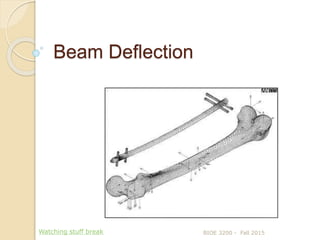
- 1. Beam Deflection BIOE 3200 - Fall 2015Watching stuff break
- 2. Learning Objectives Define beam deflection (δ) and identify the factors that affect it Determine deflection and slope in beams in bending using double integration method BIOE 3200 - Fall 2015
- 3. Deflection in beams Deflection is deformation from original position in y direction BIOE 3200 - Fall 2015
- 4. Recall relationships between shear force, bending moment and normal stresses BIOE 3200 - Fall 2015 To balance forces within beam cross section: P = σx 𝑑𝐴 V = 𝑥𝑦 𝑑𝐴 𝑀 𝑧 = − σx 𝑦 𝑑𝐴 𝑥𝑦
- 5. Bending moments balance normal stresses across area of cross section. This is how we relate applied loads and deformation (stress and strain). BIOE 3200 - Fall 2015 Simplify: 𝑀𝑧 = 𝐸 𝑑2 𝑢 𝑜𝑦(𝑥) 𝑑𝑥2 𝑦2 𝑑𝐴 Recall that 𝐼x = 𝑦2 𝑑𝐴 So: where u0y(x) is displacement in y direction
- 6. General formula for beam deflection involves double integration of bending moment equation Governing equation for deflection: 𝑑2δ 𝑑𝑥2 = 𝑀(𝑥) 𝐸𝐼 , where deflection δ(x) = uoy(x) Solve double integral to get equation for δ(x) (elastic curve), or the deflected shape Shape of beam determined by change in load over length of beam BIOE 3200 - Fall 2015
- 7. How to calculate beam deflection using double integration method BIOE 3200 - Fall 2015 δ(x) EI = Flexural Rigidity Governing equation: 𝑑2δ 𝑑𝑥2 = 𝑀 𝐸𝐼 𝐸𝐼 𝑑δ 𝑑𝑥 = 0 𝑥 𝑀 𝑥 𝑑𝑥 + 𝐶1 Note: 𝑑δ 𝑑𝑥 = tan θ ≈ θ(x) 𝐸𝐼θ(x) = 0 𝑥 𝑀 𝑥 𝑑𝑥 + 𝐶1 𝐸𝐼δ = 0 𝑥 [ 0 𝑥 𝑀 𝑥 𝑑𝑥 + 𝐶1 ] dx + 𝐶2 𝐸𝐼δ = 0 𝑥 𝑑𝑥 0 𝑥 𝑀 𝑥 𝑑𝑥 + 𝐶1x + 𝐶2 - general formula for beam deflection
- 8. Sign conventions for beam deflection X and Y axes: positive to the right and upward, respectively Deflection δ(x): positive upward Slope of deflection at any point 𝑑δ 𝑑𝑥 and angle of rotation θ(x): positive when CCW with respect to x-axis Curvature (K) and bending moment (M): positive when concave up (beam is smiling) BIOE 3200 - Fall 2015 δ(x)
- 9. What affects deflection? Bending moment ◦ Magnitude and type of loading ◦ Span (length) of beam ◦ Beam type (simply supported, cantilever) Material properties of beam (E) Shape of beam (Moment of Intertia I) BIOE 3200 - Fall 2015
- 10. How to complete double integration 𝐸𝐼δ = 0 𝑥 𝑑𝑥 0 𝑥 𝑀 𝑥 𝑑𝑥 + 𝐶1x + 𝐶2 Find C1 and C2 from boundary conditions (supports) Example: cantilever beam with load at free end BIOE 3200 - Fall 2015
- 11. Using boundary conditions to calculate deflections in beams Other examples of boundary conditions: BIOE 3200 - Fall 2015
- 12. Pulling it all together Relation of the deflection δ with beam loading quantities V, M and load Deflection = δ Slope = d δ / dx Moment M(x) = EI 𝑑2δ 𝑑𝑥2 Shear V(x) = - dM/dx = - EI 𝑑3δ 𝑑𝑥3 (for constant EI) Load w(x) = dV/dx = - EI 𝑑4δ 𝑑𝑥4 (for constant EI) BIOE 3200 - Fall 2015
- 13. Load, moment, deformation and slope can all be sketched for a beam BIOE 3200 - Fall 2015
- 14. Procedure for calculating deflection by integration method Select interval(s) of the beam to be used, and set coordinate system with origin at one end of the interval; set range of x values for that interval List boundary conditions at boundaries of interval (these will be integration constants) Calculate bending moment M(x) (function of x for each interval) and set it equal to EI 𝑑2δ 𝑑𝑥2 Solve differential equation (double integration) and solve using known integration constants BIOE 3200 - Fall 2015
- 15. Typical deflection equation Simply supported beam under uniform constant load: δx = 𝑤 𝑥 24 𝐸 𝐼 (𝑙3 − 2 𝑙 𝑥2 + 𝑥3 )(at any point x) BIOE 3200 - Fall 2015 Loa d Material Property Shape Propert y L Δmax Span
- 16. Examples of deflection formulae FBD for simply supported beam under constant uniform load: δmax = 5 𝑤 𝑙4 384 𝐸 𝐼 (at midpoint) δx = 𝑤 𝑥 24 𝐸 𝐼 (𝑙3 − 2 𝑙 𝑥2 + 𝑥3 )(at any point x) BIOE 3200 - Fall 2015
- 17. Examples of deflection formulae Simply supported beam, point load at midspan δmax = 𝑃 𝐿 𝑜 3 48 𝐸 𝐼 (at point of load) δx = 𝑃 𝑥 48 𝐸 𝐼 (3 𝐿 𝑜 2 − 4 𝑥2 ) (where x < 𝐿 𝑜 2 ; symmetric about midspan) BIOE 3200 - Fall 2015 x
- 18. Examples of deflection formulae Cantilever beam loaded at free end δmax = 𝑃 𝐿3 3 𝐸 𝐼 (at free end) δx = 𝑃 𝑥 2 6 𝐸 𝐼 (3 𝐿 - 𝑥)(everywhere else) BIOE 3200 - Fall 2015 P
Editor's Notes
- Long bone curvature results in bending when compressive loads applied; convex surface under tension, convex surface under compression.
- Unloaded beam: neutral axis is level Applied load: neutral axis bends and takes on curved shape Distance d (also delta; maximum deflection is delta max) is distance between unloaded and loaded neutral axis (NA). Delta max occurs at mid-span of simply supported beam, or at free end of cantilever beam
- The axial stress σx produces a moment about the z-axis that must be equivalent to the moment resultant Mz. In other words, σx balances moment Mz, and Mz balances σx
- Recall that stress = strain x Young’s modulus (𝜖E) Note that we must integrate Mz over the cross-section A, which lies in the y-z plane. Assume that Young's modulus E is a constant over the cross-section, and thus E may be taken outside the integral. Since uoy(x) is not a function of y or z, it may also be taken outside the integral. Replacing strain and E for stress, moment equation includes E and second derivative of displacement term u(x). This is also called delta (δ) Iz = Second moment of area Note EI = flexural rigidity; material and shape property of beam, assumed to be constant throughout beam (unless otherwise noted)
- The equation for beam deflection is an ordinary second order differential equation. It defines the transverse displacement in terms of the bending moment. We know that bending moment Mz is a function of position x along the beam, and we have already learned how to determine the equation for Mz. So deflection can be determined by double integrating the equation for M. Note: EI = flexural rigidity
- Integrate 2nd order differential equation twice to get expression for δ(x) θ(x) – approximate slope at location Q along the beam for small deflections, because d𝛅 dx = tan θ ≈ θ(x) for small deflections Beam deflection defined between two points; red curve represents the deflected shape of the beam. Can express elastic curve as a function of x – get equation of line, can get deflection at any point on the beam. Governing equation: M = complete equation for moment distribution along a beam; Differential equation can be integrated in each particular case to find the deflection delta, provided by bending moment M and flexural rigidity EI are known.
- Beam between two points; red curve represented the deflected shape of the beam. Can express elastic curve as a function of x – get equation of line, can get deflection at any point on the beam. Governing equation: M = complete equation for moment distribution along a beam; Differential equation can be integrated in each particular case to find the deflection delta, provided by bending moment M and flexural rigidity EI are known. EI = flexural rigidity
- Higher magnitude, more deflection; Uniform load produces less deflection than single point (same equivalent resultant) Same load on a longer beam will be greater than on a shorter beam Stiffer beam (higher E) will deflect less Shape of beam – mainly cross section (rectangular, circular, I-shape)
- At points A and B for simply supported beam, deflection = 0 For cantilever, slope and deflection at A = 0 Use these boundary conditions to calculate C1 and C2 (2 constants, 2 boundary conditions) (1) the x and y axes are positive to the right and upward, respectively; (2) The deflection ν is positive upward; (3) The slope dν dx and angle of rotation θ are positive when counterclockwise with respect to the positive x axis; (4) The curvature k is positive when the beam is bent concave upward; and (5) the bending moment M is positive when it produces compression in the upper part of the beam.
- For more complex loading scenarios where equation for moment cannot be defined for entire x, cut beam into sections where M can be represented by one function – concentrated loads, discontinuity in distributed loads
- Sign convention: (1) the x and y axes are positive to the right and upward, respectively; (2) The deflection ν is positive upward; (3) The slope dν dx and angle of rotation θ are positive when counterclockwise with respect to the positive x axis; (4) The curvature k is positive when the beam is bent concave upward; and (5) the bending moment M is positive when it produces compression in the upper part of the beam.
- Example (W is a distributed load): At any distance x from left to right (except midspan) Delta max is at mid-span
- Delta max is at mid-span
- Delta x left or right of midspan, deflection will be less than delta max (deflection at midspan)
- All these equations have the same elements: load, geometry, material properties and shape properties