X.25
•
6 likes•5,198 views

X.25 is a packet-switched network, developed by ITU-T as an interface between data terminal equipment DTE and data circuit-terminating equipment DCE for terminal operation in packet mode on public data network. It is an end-to-end protocol, but actual movement of packet through the network is invisible to the user.The user sees the network as a cloud through which each packet passes on its way to the receiving DTE. It defines how a packet-mode terminal can be connected to a packet network for exchange of data. It describes procedures necessary for establishing, maintaining and terminating connections. It uses virtual network approach to packet switching, SVC and PVC and uses asynchronous TDM to multiplex data...

Recommended
More Related Content
What's hot
What's hot (20)
Similar to X.25
Similar to X.25 (20)
More from Madhumita Tamhane
More from Madhumita Tamhane (20)
Recently uploaded
Recently uploaded (20)
X.25
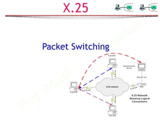
- 1. Prof. M adhumita Tamhane X.25 Packet Switching
- 2. Prof. M adhumita Tamhane X.25 » Packet-switching wide area network developed by ITU-T. » X.25 is subscriber network interface (SNI) protocol. » Defines how data terminal equipment (DTE) communicates with the network to send packets over it using data circuit-terminating equipment (DCE). » It uses virtual circuit approach to packet switching (SVC and PVC). » Uses asynchronous TDM to multiplex packets. » It describes procedure for establishing, maintaining and terminating connections.
- 3. Prof. M adhumita Tamhane X.25 Layers » Physical layer, frame layer and packet layer define function at physical, data link and network layers respectively of OSI model.
- 4. Prof. M adhumita Tamhane X.25 Layers » Physical Layer : » X.25 specifies a protocol X.21 defined by ITU-T. » X.25 supports all other physical layer protocols too like EIA-232 etc as X.21 is similar to them. » Frame Layer: » X.25 provides data link controls using a bit-oriented protocol called Link Access Procedure-Balanced (LAPB). » LAPB is subset of HDLC, comprising of point-to-point and asynchronous balance mode. I-frame: User data S-frame: Empty U-frame: Control data
- 5. Prof. M adhumita Tamhane X.25 Layers-Frame Layer » X.25 being point-to-point and asynchronous balance mode support only two addresses at frame layer: » 00000001 for a command issued by a DTE and the response to this command. » 00000011 for a command issued by a DCE and the response to this command.
- 6. Prof. M adhumita Tamhane Frame Layer-Categories of frame » I-frame: Used to encapsulate packet layer protocol (PLP) packets from the network layer. » S-frame:Flow and error control in frame layer. » U-frame: To set up and disconnect the links between a DTE and a DCE. » Most common U-frame packets are Set Asynchronous Balance Mode (SABM), Un-numbered Acknowledgement (UA) or Disconnect (DISC).
- 7. Prof. M adhumita Tamhane Frame Layer-Phases » Link Setup: » Link between DTE and DCE must be setup before packets from packet layer must be transferred. » Either DTE or DCE can setup link by sending an SABM frame. » Responding party sends a UA frame to show link setup. » Transferring Data: » After link establishment, DTE and DCE can send and receive network layer packets(data and control) using I-frame and S-frame. » Link Disconnect: » One of the parties can issue a disconnect(DISC) frame to request disconnect. » Other party can answer with a UA frame.
- 8. Prof. M adhumita Tamhane Packet Layer » Network layer in X.25 is called packet layer protocol PLP. » Responsible for connection establishment, data transfer, and connection termination. » Responsible for creating virtual circuit, negotiating network services between two DTEs. » Unlike frame layer, packet layer is responsible for end-to-end connection(DTE to DTE). » X.25 uses flow and error control at two levels: » between DTE and DCE by frame layer » between two DTEs by packet layer.
- 9. Prof. M adhumita Tamhane Virtual Circuits » X.25 is packet-switched virtual circuit network. » Virtual circuit created at network later. » Physical layer between DTE and DCE can carry many virtual circuits at network layer. » Each VC responsible for carrying either data or control information (In-Band-Signalling).
- 10. Prof. M adhumita Tamhane Virtual Circuit Identifiers » In X.25, Virtual Circuit Identifiers are called Logic Channel Number. » VC establishment between two DTEs creates two LCNs: » One defining VC between a local DTE and a local DCE. » Other defining VC between remote DTE and remote DCE.
- 11. Prof. M adhumita Tamhane LCNs in X.25 » Two different LCNs helps in making LCN domain local. » This allows set of LCNs for each local connection to be small and hence short LCN field. » Also same LCNs can be reused between two different DTE-DCE links without any global confusion. ! » Global LCN would require a larger set of LCNs and hence large LCN field. » Moreover LCNs can not be reused as global uniqueness is lost.
- 12. Prof. M adhumita Tamhane PVCs and SVCs in X.25 » X.25 uses both permanent PVC and switched virtual circuits SVC. » PVCs are similar to telephone leased line and are permanently assigned and established by X.25 network providers. » SVCs are established at each session by network layer using a control packet. » After connection establishment, both DTE-DCE links are assigned LCNs. » After data transfer, VC is disconnected and LCNs are invalid. » VC establishment and release at network layer are different from link set-up and disconnect at frame layer.
- 13. Prof. M adhumita Tamhane SVC setup in X.25 » A link is setup between local DTE and DCE and also between remote DTE and DCE. » A virtual circuit is established between a local DTE and and the remote DTE. » Data are transferred between the two DTEs. » The virtual circuit is released. » The link is released.
- 14. Prof. M adhumita Tamhane LCN Assignment » X.25 allows unto 4096 (212) LCNs. » One-way LCNs are used for simplex connection. » Two-way LCNs are used for duplex communications.
- 15. Prof. M adhumita Tamhane PLP Packets » PLP packet format has 3 or 4 bytes of header and an optional information frame.
- 16. Prof. M adhumita Tamhane PLP Packets » General Frame Identifier(GFI): 4 bits » Bit 1: Q (qualifier) bit - defines source of control information: » 0-PLP » 1- other higher level protocol » Bit 2: D (delivery) bit - defines which device should acknowledge the packet: » 0-local DCE » 1- remote DTE » Last two bits: indicates size of sequence number field: » 01: 3-bit sequence numbering- modulo 8(0 to 7) » 10: 7-bit sequence numbering- modulo 128(0 to 127)
- 17. Prof. M adhumita Tamhane PLP Packets » Logical Channel Number(LCN): 12 bits » Identifies virtual circuit chosen for a given transmission. » LCN was originally given hierarchal sense by dividing LCN as: » 4 bits- LGCN logical group channel number » 8 bits- logical channel number » Packet Type Identifier(PTI): 8/16 bits » Defines type of packet. » Contents of this field depends on packet type. » Two categories of packet:
- 18. Prof. M adhumita Tamhane PLP-Data Packets » Transmits user data. » Header and user data field. » Packet type identifier PTI consists of packet send P(S) and packet receive P(R) for flow and error control. » P(S) indicates sequence number of packet being sent. » P(R) is sequence number of next packet that the receiver is expecting to receive. » This field is also used to piggyback acknowledgement to data packets when both parties have data to send. » Two formats for information packets. » Short format: P(S) and P(R) are 3 bits long.(GFI—QD01) » Sequence numbers from 0 to 7.(GFI—QD10) » Long format: P(S) and P(R) are 7 bits long. » Sequence numbers from 0 to 127.
- 19. Prof. M adhumita Tamhane PLP-Data Packets » M bit expresses if more packets belonging to same message. » M=1 —More packets of same message to follow. » M=0 —Current packet is last packet of a message. » 0 in LSB of third byte indicates information packet. Q D 1 0 LCN LCN P(R) 0 P(S) M User Data Seven bit sequence number Q D 0 1 LCN LCN P(R) M P(S) 0 User Data Three bit sequence number
- 20. Prof. M adhumita Tamhane Control Packets-RR, RNR, REJ » Receive Ready (RR), Receive Not Ready (RNR) and Reject (REJ) packets have headers with 01 in two LSBs of third row. » Only for flow and error control— » Carry no data. » No P(S). » Packet type:— Q D 0 1 LCN LCN P(R) Packet Type 0 1 Q D 1 0 LCN LCN Packet Type 0 1 P(R) 0 Three bit sequence number Seven bit sequence number
- 21. Prof. M adhumita Tamhane Control Packet Type » RR (000):— Receive ready means that DTE or DCE is ready to receive more packets. » It also acknowledges receipt of all {P(R)-1} data packets sent before. » Expecting to receive data packet numbered P(R). » RNR (001):— Receive not ready means that DTE or DCE is not ready to receive more packets. » It also acknowledges receipt of all {P(R)-1} data packets sent before. » REJ (010):— Reject means error detected in packet numbered P(R). » Other party must resend all packets from P(R) onwards. » Go-Back-n error control. » Expecting to receive data packet numbered P(R).
- 22. Prof. M adhumita Tamhane Other Control Packets » Identified by 11 in two LSBs of third row. » May carry information only for control purposes and not data. » Only one size of header, as no P(R) and P(S) fields. » Packet type 6 bits long, giving 64 different possible functions. » Few functions described are:— Q D 0 1 LCN LCN Packet Type 1 1 Additional Information Unnumbered Packets
- 23. Prof. M adhumita TamhaneDTE to DCE DCE to DTE Type Discription Local Call Request Remote Incoming Call 0 0 0 0 1 0 Request connection establishment between two DTEs. Facilities are optional, on agreement between users and networks. Contractual options like incoming/outgoing calls barred, flow control parameter negotiations, fast select, reverse charging, etc.. Remote Call accepted Local Call Connected 0 0 0 0 1 1 Indicated acceptance of packets by called system. Sent in response to call request and incoming call packets. Header Address Length DTE Address Facility Length Facilities Header Address Length DTE Address Facility Length Facilities Other Control Packets
- 24. Prof. M adhumita TamhaneDTE to DCE DCE to DTE Type Discription Clear Request Clear Indication 0 0 0 1 0 0 Used at end of an exchange to disconnect(clear) connection by DTE or DCE. Can also be used by remote DTE to respond negatively to incoming call if unable to accept. Clear Confirm Clear Confirm 0 0 0 1 0 1 Sent in response to clear indication. Interrupt Interrupt 0 0 1 0 0 0 Under unusual circumstances to break into exchange to get attention, by DTE/DCE. ALERT. E.G.user doesn’t get ACK/NACK for long. Interrupt Confirm Interrupt Confirm 0 0 1 0 0 0 Confirms receipt of interrupt packet. Header sent. Header Cause Diagnosis Header Other Control Packets Header
- 25. Prof. M adhumita TamhaneDTE to DCE DCE to DTE Type Discription Reset Request Reset Indication 0 0 0 1 1 0 To reset sequence numbers in data exchange over a particular VC if wants reinitialisation. VC remains active but transmission re-starts from a predetermined point. Packets renumbered from 0. Reset Confirm Reset Confirm 0 0 0 1 1 1 Confirms reset process Restart Request Restart Indication 1 1 1 1 1 0 Restarts all VCs created by DTE. Different from reset(which only resets packet numbering over existing VCs).Establishes new VCs. P(S) from 0. Restart Confirm Restart Confirm 1 1 1 1 1 1 Confirms restart request. Header sent. Header Cause Diagnosis Header Other Control Packets Header Cause Diagnisis
- 26. Prof. M adhumita TamhaneDTE to DCE DCE to DTE Type Discription Registration Request 1 1 1 1 0 0 Allows on-line registration of new user to the network Registration Confirm 1 1 1 1 0 1 Confirms registration Header Address Length DTE Address Registration Length Registration Header Address Length DTE Address Registration Length Registration Other Control Packets
- 27. Prof. M adhumita Tamhane X.25-Call Establishment Packet
- 28. Prof. M adhumita Tamhane X.25-Call Establishment
- 29. Prof. M adhumita Tamhane Data Transfer phase D=0
- 30. Prof. M adhumita Tamhane Data Transfer phase D=1
- 32. Prof. M adhumita Tamhane INTERRUPT – Urgent Data after window exhausted
- 34. Prof. M adhumita Tamhane Grouping of logical channels
- 35. Prof. M adhumita Tamhane X.121 protocol » X.25 does not define Global addressing for call setup to access remote DTE before SVC establishment. » X.25 uses X.121(by ITU-T) to globally address DTEs connected to public data networks. » 14 digit address format has — » First 4 digits Data Network Identification Code (DNIC) defines specific network with » 3 digits for country » 1 digit for network inside country » Next 10 digits National Terminal Number(NTN) defines DTEs inside a particular network. DNIC NTN Country Code Network Number 4 digits 10 digits 1 digit3 digits
- 36. Prof. M adhumita Tamhane Tripple X protocol » X.3, X.28 and X.29 collectively are called Triple X Protocols. » Used to connect a dumb terminal to X.25 network. » Dumb terminal can not understand X.25.
- 37. Prof. M adhumita Tamhane Tripple X protocol » X.3 :- » Defines packet assembler/disassembler(PAD). » Needed to connect a character oriented(dumb) terminal to an X.25 network. » A PAD buffers dumb-terminal character keys and assembles them into X.25 packet. » At receiver, it disassembles the X.25 packet so as to be displayed on the screen or printed on printer. » X.3 defines 22 parameters to be used by PAD. » X.28 :- » Defines rules for communication between a dumb terminal in (Asynchronous character mode) and a PAD. » Defines commands for dumb terminal or PAD for various X.25 activities.
- 38. Prof. M adhumita Tamhane Tripple X protocol » X.29 :- » Defines relationship between a PAD and a remote terminal. » Using X.29, a remote terminal can set some parameters in packet mode in PAD. » Defines how the PAD encapsulates characters and control information in X.25 packets. » Example: Echo.