
Recommended
Recommended
More Related Content
Similar to RR-Ship-Shape-Oct-2015-RRS-Timpane
Similar to RR-Ship-Shape-Oct-2015-RRS-Timpane (20)
More from Michael Timpane
RR-Ship-Shape-Oct-2015-RRS-Timpane
- 1. “I wish to have no connection with any ship that does not sail fast.” -John Paul Jones, American Revolutionary War naval leader Most of the major MRF equipment vendors and operators have reported recently slow pipelines and delayed or cancelled orders for retrofits or new facilities. They have a reason for concern. Government records show that residential recycling in the U.S. grew for 50 years straight, until last year, when it dropped slightly. And the downward trend will continue at least for a few more quarters, if not more. The major financial reset in residential MRF economics from failing commod- ity markets and higher costs, and the shakeout that the industry is coping with now, will stagnate recyclable volumes. This year will certainly be a washout, as recalcitrant programs take on contami- nation, marginal materials are banished to disposal and the nation’s fleet of merchant MRFs taking material continues to shrink. Many industry experts have speculated that the number of facilities that could close during this protracted slump could be 15-20 percent of the market. And, in fact, in the last 12 months, many public and private companies have announced MRF closings and asset sell-offs. The reasons for today’s MRF struggles are multifaceted: a lack of adaptability to customers’ preferences for more accepted materi- als, unused expensive capacity due to a lack of volume, loss of key contracts and more. However, on top of all those issues, is the problem of design. More than a few MRFs on the landscape feature material flow arrangements that do not help the case for sustained operations. In short, they are not producing the desired results at a sustainable cost. The future MRF will require constant investment and change. These re-tooled or new MRFs must be flexible, reliable and strive for flank speed. That means the industry must develop facilities and retrofits that can withstand down market times. Even while many operations shut down, plants have been started or are planned in Atlanta; Cocoa Beach, Fla.; Dallas; Milwaukee; Oakland, Calif.; and Sun Valley, Calif. to name just a few. Given the mixed conditions, planning better MRFs is imperative even as some walk the plank. Are there axiomatic lessons for the design and layout of physical facilities, which can help MRF processing effectiveness and get op- erations through the ups and downs of market vagaries? Yes. Best practices and operating MRF examples are available and recom- mended for analysis as part of every retrofit and new facility design to alleviate downstream bottlenecks and lack of adaptability to new conditions. The lessons are simple and straightforward – and they reduce cost. This will help on the margin side over the entire time the facility is operated, and may help to navigate through times like the current ones. Yet essential best practices in MRF design are often compro- mised as MRF planners find themselves skimping because they are “between the devil” (capital budget, property size and building lim- itations) and “the deep” (later higher costs). Many times, planners are awarded on hitting capital budgets and not often on later issues unless the MRF is owner-operated. Let’s look at MRF fixed equipment, and the simplest or easiest Ship ShapeIN THE THIRD PART OF A SERIES ON THE MODERN MRF, OUR EXPERTS LAY OUT DESIGN PRINCIPLES AND EQUIPMENT CONSIDERATIONS THAT MAKE FOR MORE SUCCESSFUL PLANTS IN GOOD TIMES AND BAD. BY MICHAEL TIMPANE AND KERRY SANDFORD Reprinted from 16 RR | October 2015
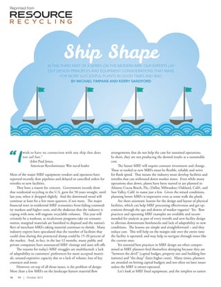
- 2. RR | October 2015 17 considerations for plant layout and equip- ment when designing or retrofitting MRFs. The underlying economic question throughout the discussion can be boiled down to the following: Is saving today worth the tomorrow it brings? Sailing straight ahead Over the years, MRFs have been crammed into every imaginable configuration as planners considered land and building costs, location, and the suitability of property and zoning. The tradeoffs have led to MRFs with Escher-like configurations that feature corkscrew material flows, three- and four- tier systems rising up to 40 feet high, and creature discomforts very hard to overcome. They do not work as well as other more straightforward MRFs. An old mate in the business confided that “if I go into a plant and cannot see the flow clearly, I know the plant will have issues throughout its life.” Well laid-out facilities include a number of key points. Upon first look, the trained eye can see when process steps are arranged in a “natural” order, safely linking together sorting, maintenance and cleaning. This natural flow reduces conveyor belt travel and minimizes re-circulation as well as the number of touches and transitions. In short, material processing steps are arranged in a logical order, with the shortest distance possible between each step. This is such a simple concept, but it’s not often followed in the MRF world. Like the iconic desert highway, you can put the pedal to the metal in these puppies. Henry Ford, Boeing, Toyota and the lean manufac- turing revolution have shared these concepts and proven that shortening the distance between steps brings higher efficiency. Figure 1 | Straight line “I” process flow Source: All figures and charts courtesy of RRS, 2015 INFEED SHIP Figure 2 | Typical “comb and spine” flow in a single-stream MRF CONTAINER SORT BALER INFEED BALE LARGE TO SMALL FIBER CONVEYOR BELT RESIDUE LINEGLASS CLEANING CLEAN MATERIALS STREAMS BALE INFEED SHIP SHIP SHIP RECTANGLAR BUILDING GENERAL FLOW MOVING IN ONE DIRECTION RECTANGLAR BUILDING GENERAL FLOW MOVING IN ONE DIRECTION UNSORTED INFEED
- 3. 18 RR | October 2015 Straightforward flow (or I-shaped flow) is the best pattern for MRFs, and the strategy calls for rectangular buildings rather than square ones. MRF owners have plenty of incentive to follow this recommendation. After all, the more conveyors, the higher the system price tag. In actuality, of course, even the best laid-out single-stream facilities represent a modified straight-line flow. They tend to harness a “comb and spine” arrangement, where products exit the one-way process flow at various levels for activities such as baling, trash collection and glass cleaning. Still, achieving a system that’s as close to a true I-shaped flow as possible is the goal. Such set-ups bring the following benefits: • Material is spread uniformly across belts and increases visibility for manual and automated sorting. • Larger materials are sorted from the stream first to improve visibility and sorting efficiency when it comes to smaller items. • As material is pulled from the line, successive conveyors are narrower to accommodate smaller items and smaller volumes of materials. • The depth of recyclables on the belt is fully controlled by conveyor speeds and splash transitions, so presentation to sorters and automated sorting devices is optimized for material capture, ergo- nomic comfort and other needs. • Belt feet consumed for all of the sorting and baling tasks required are at their lowest level, meaning less energy is used and less repair is needed over time. • Transitions between conveyors and the number of motors are also lowest, leading to similar gains in outage times, energy and maintenance. • Maintenance access is easier because the system can be approached from both sides. • Mixed material is tipped at one end of the building, and sorted and baled ma- terial is loaded into trailers or contain- ers at the other end. This minimizes handling of material and saves on fuel and equipment repair. Meanwhile, deviations from the straight line ideal, including “L” and “U” shaped flows, or even more complex multi-level or multidirectional MRFs, have comparative disadvantages including: • Controlling the depth of the material is not as easily accomplished, making downstream sorting and cleaning more difficult. • With every turn in the system, utili- zation of the receiving angled belt is compromised by material piling up on one side. • Wear at the splash point is concentrated in a small area. • Every transition conveyor adds initial conveyor costs and breakdown points to the motor, drive pulley and tail pulley, not to mention the belts and sprockets. But it’s the careful consideration of advan- tages and disadvantages for different kinds of flow that counts. Some counterbalancing benefits of non-straight-line flow include: • A U-shaped, L-shaped or multi-level corkscrew equipment configuration can be done in a smaller space and build- ing/land costs may be less. • Existing building retrofits may have too many location advantages to justify adoption of a rectangular flow. • Outside traffic is better controlled and more efficient in circular arrangements surrounding square buildings. These are competing upfront-cost tradeoffs, especially if you are not building new or do not have the room on a property for a long, rectangular plant. The point is that regardless of whether you are dealing with a new $30 million facility or making do with one that is there, attention needs to be paid to make bent configurations work. Not having a straight-line flow, though disadvantaged, may not sink a MRF if layout design is well thought out and minimizes unnecessary equipment and turns. Facilities can still have a clean and logical flow of material. In fact, a few very efficient MRFs defy straight-line processing logic. And manufacturers like Bollegraaf/ Van Dyk, Bulk Handling Systems (BHS), CP Group, Machinex and Sherbrooke OEM have designed layouts to overcome the inefficiencies using on-site practicalities. Some arrangements put the control station and all sorters except presort within a few steps of each other. This makes for easy management of staff and quick recognition of arising problems. Any strategy for flow will hinge on the transitions between conveyors and equip- ment. If turns are needed, the transitions should aim to get material spread across the receiving conveyor or process equip- ment without gaps. Turns may require an increased drop height as well as enclosure Figure 3 | “U” shaped flow SHIP U SHAPE INFEED
- 4. RR | October 2015 19 Figure 4 | “L” shaped equipment configuration of the splash area. Making turns without well-designed transitions leads to issues such as spillage (requiring daily or even con- tinuous cleanup labor), jams (causing line stoppage and risking damage to expensive equipment) and unevenly distributed flow (compromising the efficiency of downstream sorting activities and limiting the through- put of the system). In addition, you may need turns to use space efficiently – for example, when an operation has more than two optical sorters, it will need to stack the decks or fold them back and forth, unless the building is very long (there are space and speed advantages to foldback). The major takeaway is not to compromise the room needed in the layout to have well designed transitions. Skimping on space, while desirable for design efficien- cy, is the downfall of many expensive MRFs. Beware the compromises. If one must be made, it will be better made on the container system (as opposed to the fiber stream): Splash backs and other fixes can be employed for efficiency on three-dimension- al material more readily. The vital takeaway here is engaging in a really vigorous process flow optimization step when new/retrofitted equipment is designed and laid out. This diligence is the path to lower operating costs and larger • If a baler is down, loose paper and seg- regated containers can be sorted, stored and baled directly with only a baler operator and a forklift driver. • If the entire sorting system is down, single-stream recyclables can be baled or reloaded onto trucks for storage or nearby facilities, if available • The plant can buy in mixed paper or mixed containers at lower costs since major labor is avoided for entire system costs. The flexibility of bypass systems also includes the ability for better material com- position analysis after sorting because loose material is available and can be designed to be collected in a container, minimizing heavy/light stratification. In large systems, when the contain- er line is down, mixed rigid material can bypass processing and be stored and moved directly to the repaired line, instead of being mixed with the single-stream again and moving through the paper system a second time. Another gallingly common error in MRF design is not building in baler direct feed capacity, a move that really is a penny-wise decision. Utilizing available direct-to-baler capacity is one of the easiest ways to lower costs. Direct-to-bale com- modities will have the lowest plant costs because of limited sorting. They also will add volume to the fixed cost structure while avoiding the operating and maintenance costs involved in running the material through the sorting system. This is an easy design change that can bring much needed flexibility in operation and financial perfor- mance. Consider a 15,000-ton-per-month plant with 75 sorters and a per-ton pro- cessing cost of $60. The manager has an objective to reduce cost by 5 percent per ton (to $57 per ton) because there is a new competitor and the plant wants to keep an important contract. After reviewing op- tions, he or she decides eliminating sorters will provide the “biggest bang for the buck” (see chart 1). The facility would need to elimi- nate between 13 and 16 sorters to reach the objective. What recycling plant can eliminate that many sorters and remain effective in making saleable commodities? Assuming the manager is doing a good job, cutting into the meat of the plant is not possible. However, if the plant had direct-baler capacity, it could consider a plan to attract 5 percent more volume by accepting clean SHIP L SHAPE INFEED returns. Failure to maximize efficiency here will increase operating costs and the MRF’s competitive relevance for the life of the machinery. Much like the hidden fees in some 401(K)s, a new MRF can become an expensive investment if time is not spent on this critical design value. Bypassing and direct-to-bale Once an efficient, I-shape-influenced flow structure is established, an operator can begin digging into the more nuanced areas of design, which carry plenty of revenue implications in their own right. One com- mon mistake that is made again and again with MRF design is the lack of bypasses in the MRF processing system. Imagine a system in which single-stream material must flow completely through the system over all the belts and then 70 percent through baling before it can be removed if needed. Such situations are not uncommon, and the vulnerability is that if one part of the system breaks down, the entire plant stops processing. The larger a facility is, the more significant the ROI for effective bypass systems long-term. Handy bypasses pay dividends in the following ways:
- 5. 20 RR | October 2015 material at the lower cost associated with just baling. The move would result in around 160 tons per week better baler capacity utiliza- tion and would bring the MRF’s cost down to $57.75 per ton, more than two-thirds of the way to the cost-reduction goal (see chart 2), and the entire plant is more competitive and sustainable. Direct-bale access is a by- pass mechanism as well, and when the plant goes down for extended periods of time, it may allow the facility to ship materials to other facilities. In most cases, such access takes a side door for truck access and a slightly longer baler feed conveyor. Plug and play or drown at sea The majority of MRFs today are suddenly seeing a need for the modularization of components to a degree they never have before. MRFs are not flexible enough to meet the quickly emerging future because they were not designed for easy adapt- ability to changing streams and technol- ogy. MRFs are, for the most part, fixed monoliths – very sturdy but not effective at replacing manual sorting areas with automa- tion or today’s peripherals (eddy currents, infrared sorters, etc.) with tomorrow’s robot- ic and optic solutions (think smart robots, X-ray/optical sorting, three-dimensional sorting drums, economical advanced glass clean-up, improving air-knife systems and more). Finally, the order of each process is fixed as well, due to the needed space for each step. Much of the reason for this condition is the lead time in municipal programs, where permitting and building new facilities can be as much as five years from the beginning of the municipal planning process until the first day of operation. Public procurement cycles are lengthy, and contracts are long- term. The greater-than-40-percent ONP content of just five years ago is now nearing 25 percent of composition (and much less in recently measured sites). In addition, evolving materials such as aseptics/cartons, bulky rigid HDPE plastics, tubs and lids (Nos. 2, 4 and 5 plastics) and others are growing commodity captures at many fa- cilities, with sorters assigned to them rather than other tasks. Most five-year-old MRFs were not built with those materials in mind. In sum, MRFs today are still generally custom-made to buildings and old material streams, and components from different manufacturers are not standardized. Fur- thermore, costs for technology improvements limit action from operators. There is great work to be done here and it must be done here. The entire industry could see very positive impacts if standardization and a modular approach (even local site modularization) were implemented. Take the time to put mod- ularization and other smart ideas on the table and give them as much weight as other design considerations. It may allow your MRF ship to get to long- term safe harbors in changing seas. Michael Timpane is vice president of process optimization and recovery for Resource Recycling Systems (RRS). He can be reached at mtimpane@recycle.com. Kerry Sandford is senior engineer at RRS. He can be reached at ksandford@recycle.com. Reprinted with permission from Resource Recycling, P.O. Box 42270, Portland, OR 97242-0270; (503) 233-1305, (503) 233- 1356 (fax); www.resource-recycling.com. Chart 2 – Reducing costs per ton by baler utilization Total plant cost $900,000 Additional baling cost of 5 percent additional material at $12.50 per ton 750 x $12.50 = $9,375 New plant cost $909,375 5 percent Increase in plant volume 15,750 tons New per unit cost in the plant for all tons $57.75 per ton Chart 1 – Reducing costs per ton by cutting labor Total plant cost current $60 per ton or $900,000 per month Objective Reduce 5 percent to $57 per ton or $855,000 per month Current 75 sorters x 40 hrs. x 4.5 weeks x $15 = $202,500 Requirement to succeed Reduce $45,000 in sorting cost (1 sorter costing $2,700 per month)