10. اُشؤف ػجذ اُغيذ ٖٓٓإ د-األصٛش ٛ٘ذعخ
10
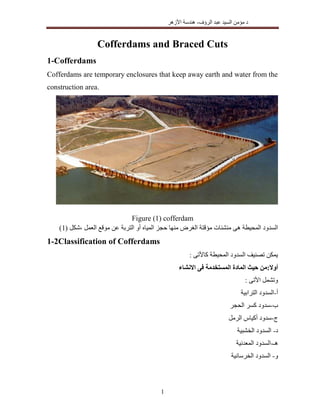
Figure (10) Double sheet pile cofferdam
Figure (11) Double sheet piles cofferdams
1-3-5 Cellular cofferdams انمتالصقح انخهىيح انسذود
A cellular cofferdam is constructed by driving sheet piles of special shapes to
form a series of cells as shown in figure (12). The cells are interconnected to
form a watertight wall. These are filled with soils to provide stability against
the lateral forces.
اُغبثوخ اُغذٝد أٗٞاع ٖٓ ٝٗٞع ٟأ يظِخ ُْٝ َاجذ ًجيش ٌَثش عذ ٠ِػ اُخبسجيخ اُؼـٞؽ صادد ئرا
ٌٕٞيز ٚٗأ ديش االعزبريٌيخ اُ٘بديخ ٖٓ أُضدٝط ٟاُغزبئش اُغذ ٚيشج ٞٛٝ ِٟٞاُخ اُغذٝد ّاعزخذا ْكيز
11. اُشؤف ػجذ اُغيذ ٖٓٓإ د-األصٛش ٛ٘ذعخ
11
اُِٞديخ اُغزبئش ٖٓ أُزالطوخ اُخاليب ٖٓ ٓجٔٞػخ ٖٓ.أٝأُٞاح ُٞديخ عزبئش ٖػ ػجبسح ِٟٞاُخ ٝاُغذ
ٓ٘بعت ّثشد ِٓئٜب ْيز ْص اُغذ ٌٓٞٗخ ثيٜ٘ب كئب َرزذاخ ٓزجبٝسح خاليب ٌُٕٞز دهٜب ْيز خبطخ ٍأشٌب راد
أُطِٞة ٕاالرضا ُزذوين.
Figure (7-12) Cellular cofferdams
1-3-1 -1Types of Cellular Cofferdams
There are two types of cellular cofferdams, namely diaphragm type cellular
cofferdam and circular type cellular cofferdam.
a)Diaphragm Type cellular cofferdam اُـشبئيخ اُغذٝد
ٓؼب يشثطٜب ُِغذ ٝاُخبسجيخ اُذاخِيخ اُ٘بديخ ٠ك دائشيخ ٓ٘ذ٘يبد ٖػ ػجبسح اُـشبئيخ اُخِٞيخ اُغذٝد
خبطخ هطغ ثٞاعطخ اُذائشيخ ثبُٔ٘ذ٘يبد رشرجؾ ٓغزوئخ ؿشبئيخ دٞائؾ,ثذجيجبد اُخاليب ِٓئ ْيز ْص
ٚػِي أُإصشح األكويخ ٟٞاُو َٔرذ ٠ِػ ٚهذسر ٠ُٝثبُزب اُغذ ٕٝص ُضيبدح ٝرُي ٖخش ّسد.يجت ًٔب
اُزشثخ ػـؾ َثلؼ اكويخ ٟٞه ُزُٞذ رج٘جب ٟٓزٞاص ٌَثش ّثبُشد أُزجبٝسح اُخاليب ِٓئ ْيز ٕأ ٓشاػبح
ٖٓ اُ٘ٞع ٛزا ٝئزبص ٠اُـشبئ اُذبئؾ ٖٓ ٝادذح ٗبديخ ٖٓ ّاُشد ُٞجٞد ٗزيجخ ٠اُـشبئ اُجذاس ٠ِػ
٠اُـشبئ اُذبئؾ ٍٞؽ ثضيبدح ٕاالرضا ٠ِػ ٚهذسر صيبدح ثآٌبٗيخ اُغذٝد.
This type of cellular cofferdam consists of circular arcs at the inner and outer
sides, which are connected by straight diaphragm walls as shown in figure
(13). The connection between the curved parts and diaphragms are made by
12. اُشؤف ػجذ اُغيذ ٖٓٓإ د-األصٛش ٛ٘ذعخ
12
means of specially fabricated Y- elements. The cofferdam is made from
interconnected steel sheet piles. The cells are filled with coarse-grained soils,
which increase the weight of the cofferdam and its stability. The leakage of
the cofferdam is also reduced. To avoid rupture of the diaphragm due to
unequal pressures on the two sides, it is essential to fill all the cells at
approximately the same rate. The advantage of the diaphragm type is that the
effective width of the cofferdam may be increased easily by lengthening the
diaphragm.
Figure (13) Diaphragm cellular cofferdams
b) Circular Type cellular cofferdam اُذائشيخ اُغذٝد
ثخاليب ٓؼب ٓشرجطخ ْاُذج ًجيشح اُذائشيخ اُخاليب ٖٓ ٓجٔٞػخ ٖػ ػجبسح اُـشبئيخ اُذائشيخ اُغذٝد
اطـش دائشيخ.ٍاألدٔب يٞصع ٟاُز ٟاُذائش ُشٌِٜب ٗزيجخ ثزارٜب ٓغزوِخ اُخاليب ٖٓ خِيخ ًَ ٝرؼزجش
ثزارٜب ٓغزوِخ ػِٔيخ خِيخ ًَ ّسد ػِٔيخ َيجؼ ٓٔب اُوششيخ أُ٘شئبد ٠ِػ ٍاألدٔب رٞصيغ ٚيشبث ٌَثش
ٟاألخش ِٞر ٝادذح اُخاليب ّسد ٌٖٔي ثذيش.ٍاألدٔب َٔرذ ٠ِػ اُؼبُيخ ثوذسرٜب رٔزبص اُذائشيخ ٝاُخاليب
13. اُشؤف ػجذ اُغيذ ٖٓٓإ د-األصٛش ٛ٘ذعخ
13
أًجش ُؼذد الدزيبجٜبًاٗظش رٌِلخ ٜٓ٘ب أًضش ٌُٜٝ٘ب اُـشبئيخ اُخاليب ٖٓ أًجش ٌَثش ػِيٜب اُٞاهؼخ األكويخ
أُؼذاد ديش ٖٓ ٝاُزشًيت اُذم ٠ك ػبُيخ آٌبٗيبد ٠ُئ ادزيبجٜب ٠ُئ ثبإلػبكخ اُذائشيخ اُوطغ ٖٓ
أُذسثخ أُبٛشح ٝاُؼٔبُخ.
It consists of a set of large diameter circular cells interconnected by arcs of
smaller diameter. This is shown in Figure (14). The walls of the connecting
cells are perpendicular to main circular cell of large diameter. The segmental
arcs are joined by special T-pile to the main cell. The circular type of cellular
cofferdam is self sustaining, independent of the adjacent circular cells. Each
cell can be filled independently. The stability of such cells is much larger as
compared with the diaphragm type. The circular type is more expensive as
compared to the diaphragm type, because these require more sheet piles and
skilled technology for setting and driving the pile. As the diameter of the
circular cell is limited by interlock tension, their ability to resist large lateral
pressures due to high head is restricted.
Figure (14) Circular cellular cofferdams
14. اُشؤف ػجذ اُغيذ ٖٓٓإ د-األصٛش ٛ٘ذعخ
14
Problem (1)
State the types of cofferdams, indicating the circumstances under which each
is most suitable.
Solution
a)Following are some of the common types of cofferdams
(1) Earth fill cofferdam
(2) Rock fill cofferdam
(3) Single wall cofferdam
(4) Double wall cofferdam.
(5) Cellular cofferdam.
b) Circumstances:
(1) Earth fill cofferdam:- The use of this variety is limited in the vicinity
where the impervious earth is available and the water depth is shallow with
low velocity of flow. This type is not used where there is danger of
overtopping of water.
(2)Rock fill cofferdam:- These are constructed by placing rock along stream.
They can be used for depths of water up to about 3 m and are suitable even in
swift waters. These are economical in places where rock is available in plenty.
(3)Single wall cofferdam:- This type of cofferdam is suitable when available
working space is limited and area enclosed is small. It can be used up to a
depth of water equal to 25 m.
(4) Double wall cofferdam:- Double wall cofferdams are provided to enclose a
larger area. This type is useful where scour problems and space limitations are
prevalent.
(5) Cellular cofferdam:- These are suitable for dewatering large areas. These
can withstand overtopping of water. These types of cofferdams are used in
case of bridges with long spans.
16. اُشؤف ػجذ اُغيذ ٖٓٓإ د-األصٛش ٛ٘ذعخ
16
Where:
W=B {(H-H1) γT+H1 γsub} ٕٝصاُخِيخ َداخ اُزشثخ
Pw= 0.5γw H2
أُبئيخ أُغذخ ٗبديخ ٖٓ ٙأُيب ػـؾ ٓذظِخ
PA=0.5γsub Ka H2² ٍاُلؼب اُزشثخ ػـؾ ٓذظِخ
Pp= Ppˋ+Pw1 ّٝأُوب اُزشثخ ػـؾ ٓذظِخ+ُِغذ ٠ِاُذاخ ٚاُٞج ٗبديخ ٖٓ ٙأُيب
Ppˋ=0.5γsub Kp H4² اُغذ ُٚٞج اُذاخِيخ اُ٘بديخ ٖٓ ّٝأُوب اُزشثخ ػـؾ ٓذظِخ
Pw1= 0.5γw H3
2
ُِغذ اُذاخِيخ اُ٘بديخ ٖٓ ٙأُيب ػـؾ ٓذظِخ
λ =0.5 for smooth rock, اُغذ ػِيٜب أُشرٌض اُزشثخ ٝ اُغذ َداخ اُزشثخ ٖثي االدزٌبى َٓٓؼب
λ = tan ϕ for other soil
Figure (15) Forces affected on cellular cofferdams
ب-االوقالب ضذ انسالمح اختثار
Check against overturning can be calculated by taking a moment about point
A, as follow:
Where:
MR =Resistance moment
50.125.1
W.
=.S.
pAW pPP
F
50.33=.S.
O
R
M
M
F
17. اُشؤف ػجذ اُغيذ ٖٓٓإ د-األصٛش ٛ٘ذعخ
17
MO= Overturning Moment
د-األساش ترتح ًف االوهيار ضذ انسالمح اختثار
Factor of safety can be calculated as follow:
Where:
qult ٠ششيط ألعبط ٠االهظ َاُزذٔي جٜذ
٠ٛٝ ٟاألخش االخزجبساد ٖٓ ٓجٔٞػخ رٞجذ ًٔب:
د-اُغذ ٓذٞس ػ٘ذ ٠اُشأع ثبُوض االٜٗيبس ػذ اُغذ عالٓخ اخزجبس
ٙ-االعبط ٝرشثخ ّاُشد ٖثي ٠دجيج ٍاٗلظب دذٝس ػذ اُغذ عالٓخ اخزجبس
ٝ-٠ِاُذاخ ّاُشد ٠ِػ اُخبسجيخ ُِغزبئش اٗضالم دذٝس ػذ اُغذ عالٓخ اخزجبس
ص-٠ِاُذاخ اُ٘ذش ػذ اُغذ عالٓخ اخزجبس
Problem (2)
Design the cofferdam shown in the figure below:
332
.
= 3
1
4
1R
HP
H
P
BW
M wp
33
P=
2
wo
H
P
H
M a
50.20.2
/6/
=.
2
b.c
BMBW
q
F
O
ult
18. اُشؤف ػجذ اُغيذ ٖٓٓإ د-األصٛش ٛ٘ذعخ
18
Solution
B=0.85 H = 0.85x20=17m
Where the fill is fine particles, so the inclination of saturation line =3:1
H3=20-17/3=14.34 m
H1=20-8.5/3=17.16m
ka=(1-sin35°)/(1+sin35°) = 0.27
kp=3.69
PA=0.5γsub Ka H2² = 0.5x10x0.27x8²= 86.4kN, ya=8/3=2.67m
Pw= 0.5γw H2
= 0.5x10x20²=2000 kN, y1= 20/3=6.67m
Ppˋ=0.5γsub Kp H4² = 0.5x10x3.69x5²=461.25kN, yp=5/3=1. 67m
Pw1= 0.5γw H3
2
=0.5 x10 x 14.34²= 1028.178kN, y2=4.78m
Pp= Ppˋ+Pw1 = 461.25+1028.178=1489.428kN
W=B {(H-H1) γT+H1 γsub}=17{ (20-17.16)x18+17.16x 8}=3202.8kN
Check against sliding
W=3202.8kN
λ = tan ϕ=tan35°=0.7
50.125.1
W.
=.S.
pAW pPP
F
safe
x
F 50.125.175.3
42.14894.862000
7.08.3202
=.S.
19. اُشؤف ػجذ اُغيذ ٖٓٓإ د-األصٛش ٛ٘ذعخ
19
Check against overturning:
Check against overturning can be calculated by taking a moment about point
A.
=3202.8x8.5+461.25x1.67+1028.178x4.78 =32908.77 kN.m
= 2000x6.67+86.4x2.67=13570.68kN.m
F.S.=32908.77/13570.68=2.42<3 unsafe
Take B=20m, B/2 =10 m
W=B {(H-H1) γT+H1 γsub}=20{ (20-17.16)x18+17.16x 8}=3768kN
MR=3768x10+461.25x1.67+1028.178x4.78 =43364.97 kN.m
F.S.=43364.97/13570.68=3.2 safe
ٖٓ ٕاألٓب َٓٓؼب هئخ ٖػ ثبُزؼٞيغ ػٌغيخ ثطشيوخ َاُذ ٌُٖٔٔا ٖٓ3:3.5أُؼبدُخ ٠ك اُزؼٞيغ ْص
اُغذ ػشع هئخ ٠ِػ ٍُِٞذظ.
W=B {(H-H1) γT+H1 γsub}=B{ (20-17.16)x18+17.16x 8}=188.4B
W.B/2= (188.4B).B/2=94.2B²
MR= 94.2B²+5684.97
3.25= 94.2B²+5684.97/13570.68
B=20.34 m ≈20.5m
50.33=.S.
O
R
M
M
F
332
.
= 3
1
4
1R
HP
H
P
BW
M wp
33
P=
2
wo
H
P
H
M a
25.3=.S.
O
R
M
M
F
78.4178.102867.125.461
2
.
=R xx
BW
M
20. اُشؤف ػجذ اُغيذ ٖٓٓإ د-األصٛش ٛ٘ذعخ
20
Check on soil stresses under the cofferdam
MT=MR-Mo=94.2x20.5²+5684.97-13570.68=31701.84 kN.m
W=188.4B=188.4x20.5=3862.2kN
xˋ=MT/W =31701.84/3862.2=8.2 m
xˋ: اُغذ ٠ِػ أُإصشح ُِٟٞو أُذظِخ رأصيش ٗوطخ
e=B/2- xˋ=20.5/2-8.2=1.75m
e : اُغذ ٠ِػ أُإصشح ُِٟٞو أُذظِخ رأصيش ٝٗوطخ اُغذ ٓشًض ٖثي أُغبكخ ٠ٛ
F1,2 : اُغذ َأعل االجٜبداد
F1=3862.2/20.5 (1+ (6x1.75)/20.5)=284.9 kN/m²
F2=3862.2/20.5(1-(6x1.75)/20.5)=91.9 kN/m²>0.0 ok
)
6
1(=1,2
B
e
B
W
F
23. اُشؤف ػجذ اُغيذ ٖٓٓإ د-األصٛش ٛ٘ذعخ
23
Figure (18) Steel sheet piles
Design of Steel sheet pile
• The sheet pile can be calculated as continuous beam resting on the wales, so
the sheet pile can be designed/m
• The Wales must be designed as continues beam resting on the struts, so the
reaction on the Wales can be calculated
• With the reaction in the struts, the struts can be designed as compression
member. The moment in the strut due to its own weight and buckling must be
taken into consideration.
2-3-3 Soldier Beam
٠ِػ االٗشبء ٓٞهغ ٍٞد دهٜب ْيز ارش دشف ٌَش ٠ِػ دذيذيخ خٞاصين ٖػ ػجبسح ْاُزذػي ًٔشاد
ٖٓ ٓغبكبد1.5:2.5ٖثي اُزجٜيض عبثوخ ثالؽبد ٝأ خشجيخ اُٞاح ٝػغ ْيز اُذلش ّروذ ٝٓغ ٓزش
ٌَثبُش ًٔب أكويخ ٝدػبٓبد ػٞاسع رشًيت ْيز ْص اُذذيذيخ اُخٞاصين(19).ٌٕٞي اُذبُخ ٙٛز ٠ٝك
َبثغيط رشرٌضاسرٌبصا ٠ٝاُز اُزجٜيض عبثوخ اُجالؽبد ٝأ اُخشجيخ األُٞاح ٠ِػ ٓجبششح ٓإصش اُزشثخ ػـؾ
ثغيطخ ًٔشاد أٜٗب ٠ِػ ٠األكو ٙاالرجب ٠ك رظٔئٜب ْيز ٠ُٝثبُزب اُذذيذيخ ْاُزذػي ًٔشاد ٠ِػ
االسرٌبص.عبثوخ اُجالؽبد َكؼ سد َٔرذ سأعيخ ًٔشاد أٜٗب ٠ِػ رظٔئٜب ْيز ْاُزذػي ًٔشاد ثي٘ٔب
أٜٗب ٠ِػ رظٔئٜب ْيز ٠اُز اُذػبٓبد ٠ُئ َٔاُذ َر٘و ٠ٝاُز األكويخ اُؼٞاسع ٠ِػ ٝرشرٌض اُزجٜيض
٠اُزار ٝصٜٗب ٖػ اُ٘بشئ االٗذ٘بء ّػض ٠ُئ ثبالػبكخ األكويخ اُؼٞاسع َكؼ سد رأخز ػـؾ ػ٘بطش
االٗجؼبط ٝهئخ.
25. اُشؤف ػجذ اُغيذ ٖٓٓإ د-األصٛش ٛ٘ذعخ
25
2-4 Lateral Earth Pressure Distribution on Braced Cuts
اُزوِيذيخ اُطشم ٍخال ٖٓ ٚ٘رؼيي ٌٖٔي ٟٝاُز اُزشثخ ػـؾ ٞٛ اُغ٘ذ دبئؾ ٠ِػ أُإصشح ٍاألدٔب
ٌَثبُش أُٞػذخ اُزوشيجيخ ْاُوي ٍخال ٖٓ ٝأ أُؼشٝكخ(21)ٍخال ٖٓ ػِيٜب ٍٞاُذظ ْر ٠ٝاُز
ٝدوِيخ ٓؼِٔيخ رجبسة.
Figure (21) Lateral Earth Pressure on Braced Cuts
Problem (3)
A long trench is excavated in medium dense sand for the foundation of a
multistory building. The sides of the trench are supported with sheet pile walls
fixed in place by struts and Wales as shown in the Figure below. The soil
properties are: γ= 18.5 kN/m3
, c = 0 and ϕ = 38°
Determine:
(a) The pressure distribution on the walls with respect to depth.
(b) Strut loads. The struts are placed horizontally at distances L = 4 m center
to center.
(c) The maximum bending moment for determining the pile wall section.
(d) The maximum bending moments for determining the section of the wales.
26. اُشؤف ػجذ اُغيذ ٖٓٓإ د-األصٛش ٛ٘ذعخ
26
Solution
(a) The pressure distribution on the walls
Ka = tan2
(45 - ϕ/2)
Pa = 0.65 γ H Ka = 0.65 x 18.5 x 8 tan2
(45 - 38/2) = 23 kN/m2
27. اُشؤف ػجذ اُغيذ ٖٓٓإ د-األصٛش ٛ٘ذعخ
27
(b) Strut loads
The reactions at the ends of struts A, B and C are represented by RA, RB and Rc
respectively.
For reaction RA , take moments about B.
RA x3 - 4x23x (4/2) = 0
RA = 61.33 kN
RB1 = 23 x 4-61.33 = 30.67 kN
Due to the symmetry of the load distribution,
RB1 = RB2 = 30.67 kN, and RA = Rc = 61.33 kN.
Now the strut loads are (for L - 4 m)
Strut A, PA = 61.33 x 4 - 245 kN
Strut B, PB = (RBl + RB2 ) x 4 = 61.34 x 4 ≈ 245 kN
Strut C, Pc = 245 kN.
(c) Moment of the pile wall section
To determine moments at different points it is necessary to draw a diagram
showing the shear force distribution as shown in the figure below
MA = 0.5 x 1 x 23 = 1 1.5 kN. m
Mc = 0.5 x 1 x 23 = 1 1.5 kN. m
Mm =1.33x30.67-(23x1.33²/2)= 20.4 kN. m
28. اُشؤف ػجذ اُغيذ ٖٓٓإ د-األصٛش ٛ٘ذعخ
28
Mn = 1.33x30.67-(23x1.33²/2)= 20.4 kN. m
The maximum moment = 20.4 kN.m
A suitable section of sheet pile can be determined
(d) Maximum moment for Wales
The bending moment equation for Wales is
Mmax=RL2
/8
Where:
R = maximum strut load = 245 kN
L = spacing of struts = 4 m
Mmax= 245x42
/8=490 kN.m
A suitable section for the Wales can be determined
2-4Check to avoid heave
Braced cuts in clay become unstable as a result of heaving of the bottom of the
excavation. The bottom of a cut in sand is generally stable. When the water
table is encountered, the bottom of the cut is stable as long as the water level
inside the cut (excavation) is higher than the ground water table. In case
dewatering is needed the factor of safety, against up lift should be checked.
اُذلش هبع ٠ك اٗزلبر ُذذٝس ٗزيجخ ٓغزوش ؿيش يظجخ ٕأ ٌُٖٔٔا ٖٓ اُطي٘يخ اُزشثخ ٠ك أُغ٘ٞد اُذلش
أُطِٞة ٕاألٓب ُزذوين رأًيذيخ دغبثبد َٔثؼ ّاُويب ٠يغزذػ ٓٔب جٞكيخ ٙٓيب ٝجٞد دبُخ ٠ك ٝرُي(ًٔب
اُجٞكيخ ٙأُيب رخليغ ٓذبػشح ٠ك ٚششد عجن).