
Recommended
Recommended
More Related Content
What's hot
What's hot (20)
Similar to Design of pile cap
Similar to Design of pile cap (20)
Recently uploaded
Recently uploaded (20)
Design of pile cap
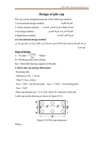
- 1. الرءوف عبد السيد مؤمن /د.م-األزهر هندسة Design of pile cap Pile cap can be designed using one of the following methods: 1-Conventional design method, الطريقةالتقليدية 2- Finite element method. المحدودة العناصر نظرية تطبيقات باستخدام 3-Circulage method, التحزيم طريقة أو الدائرية الطريقة 4-Rigid beam method, طريقةالجاسئة الكمرة a) Conventional design method من بدال الخوازيق من مركزة أفعال لردود معرضة مفردة كقاعدة الهامة تصميم يتم الطريقة هذه فى التربة جهد Steps of Design: 1- Where: Pw=Working load of the column, Qall =Allowable bearing capacity of the pile. 2- Draw pile cap and get Dimension: Assuming that: -Thickness of PC = 10 cm -Take S= Smin, where: Smin = 3xD→ for friction piles, Smin = 2.5xD → for bearing piles, Smax = 6xD -Take side distance (e) = (1:1.5) D, where D= diameter of the pile A pile cap can be drawing as shown in figure (3-3) Figure (3-3) Pile cap dimension Where: Q Pw1.15 pilesNo. all
- 2. الرءوف عبد السيد مؤمن /د.م-األزهر هندسة L=2(S+e) B=S+2e 3- Determine the pile working load a) For concentrically loaded pile cap: حملالهامة على متمركز رأسى b) For eccentrically loaded pile cap: حملالهامة على متمركز غير رأسى 4-Determine the ultimate pile load Pu (pile) =1.5 Pw (pile) 5-Design of flexure The critical section of moment is taken at the face of column as shown in figure (3-4). Figure (3-4) The critical section for moment خازوق كل عند الفعل رد حاصل مجموع = )العمود لوجه المماسين عندالقطاعين (يؤخذ االنحناء عزم الحرج القطاع عن الخازوق مركز بعد * Mu1 = Pu1xa+Pu4 x a Mu2 = Pu1xb+Pu2 x b + Pu3xb Where: pileNo.of mn)1.1Pw(colu Pw(pile) 22v y yMx. x .M N V- P Xy
- 3. الرءوف عبد السيد مؤمن /د.م-األزهر هندسة Mu1= the ultimate bending moment at sec 1-1 Mu2= the ultimate bending moment at sec 2-2 Pu1= the ultimate load for pile number 1 Pu2= the ultimate load for pile number 2 Pu3= the ultimate load for pile number 3 Pu4= the ultimate load for pile number 4 6-Calculate the pile cap depth Once calculation the bending moment the pile cap depth can be determined as follow: By taking C1=5 , get d1,d2 then choose the biggest value. Check d>dmin, dmin =1.5D+10 cm , or (dmin =2D) where D= pile diameter Take t= d+ cover , cover>700 mm .سم 7 عن يقل ال غطاء أخذ مع األكبر العمق يؤخذ ثم حدة على اتجاه لكل العمق حساب يتم حيث 7-Check of shear (one way shear) The critical section of shear is located at d/2 from face of column, where d is the depth of pile cap. :األتى مراعاة مع الهامة عمق نصف مسافة على يقع للقص الحرج القطاع 1-للقص الحرج القطاع خارج بالكامل الخازوق يقع عندما للخازوق الفعل رد قيمة كامل احتساب يتم 2-للقص الحرج القطاع داخل بالكامل الخازوق يقع عندما الخازوق فعل رد تجاهل يتم 3-من فقط الجزء هذا احتساب يتم للقص الحرج القطاع خارج الخازوق من جزء وجود حالة فى من كنسبة وذلك القص قوى حساب عند الخازوق( بشكل موضح هو كما الخازوق مساحة5-3)
- 4. الرءوف عبد السيد مؤمن /د.م-األزهر هندسة Figure (3-5) Effect of pile location on shear forces Figure (3-6) The critical section for one way shear The shear forces for the pile cap shown in figure (3-6) can be determined as follow: Qsh1-1=qu1+qu4 1-1 القطاع خارج الخوزازيق احمال مجموع Qsh2-2=zero القطاع خارج الخوزازيق احمال مجموع2-2صفر = Where: fcu =the concrete compressive strength. γc =1.5 B.d 1-Qsh1 1-qsh1
- 5. الرءوف عبد السيد مؤمن /د.م-األزهر هندسة If q sh1-1 ˂ qcu safe If qsh 1-1 > qcu un safe, increase the depth :كالتالى تقريبيا القص قوى حساب يتم الحرج القطاع داخل يقع الخازوق من جزء حالة فى الخازوق ومركز العمود وجه بين المسافة من أكبر مسافة على يقع الحرج القطاع يكون ما حالة فى الخازوق ومركز العمود وجه بين المسافة من أقل مسافة على يقع الحرج القطاع يكون ما حالة فى للخازوق الكلى القطر / القطر من القص فى المؤثر الجزء طول = التخفيض معامل أن أى Where: Fr = reduction factor D=pile diameter X= الحرج والقطاع الخازوق محور بين المسافة 8-Check of punching (two way shear) The critical section of punching is located at d/2 from each side of column as shown in figure (3-7). D D/2)(X Fr rsh FxQ uP D X)(D/2 Fr
- 6. الرءوف عبد السيد مؤمن /د.م-األزهر هندسة Figure (3-7) The critical section for punching مساحة مكونا ناحية كل من العمود وجه من الهامة عمق نصف بعد على للثقب الحرج القطاع يقع ( بالشكل موضح هو كما العمود حول الثاقب للقص7-3الحمل عن عبارة الثاقب القص ويكون ) :كالتالى وذلك الحرج القطاع داخل الخوازيق أفعال ردود منه مطروحا للعمود األقصى Qup=Pcu - ∑ Pu(pile) Where: qp=punching stress Pcu =column ultimate load للعمود األقصى الحمل Pu= pile ultimate load الحرج القطاع خارج الخازوق فعل رد U=perimeter of critical section U= 2[(a+d)+(b+d)] The allowable punching stress (qcup) is giving as the least value of the following: Where: U.d q up p Q
- 7. الرءوف عبد السيد مؤمن /د.م-األزهر هندسة qcup=the punching shear strength provided by concrete (allowable), a,b=the ratio of long side to short side of column, α=4for interior column,3 for edge column ,2 for corner column, fcu =the concrete compressive strength. If qp ˂ qcup safe If qp>qcup un safe, increase the depth : كالتالى الثقب قوى حساب فيتم للتثقيب الحرج القطاع داخل منها جزء يقع التى للخوازيق بالنسبة Qup=Pcu - λx No .of piles in critical section x pile load ultimate, As shown in figure (3-7) 9-Reinforcement of the Cap Pile: The area of steel can be determined as follow: As 1-1= → As1 /m = As 1-1/B Check : As 1-1> As min= (0.6/fy)x B x d As2-2= →=As2/m = As2-2/L Check: As2-2 > As min= (0.6/fy)x L x d 9-Details of reinforcement أو منفصلة (سواء القواعدالمسلحة لتسليح مماثال التصميم من الطريقة هذه فى الهامة تسليح يكون ( بشكل موضح كماهو وذلك )جار قاعدة أو مشتركة8-3.) j.d.fy 1-1Mu j.d.fy 2-2Mu piletheofareagross piletheofareahatched
- 8. الرءوف عبد السيد مؤمن /د.م-األزهر هندسة Figure (3-8) Details of reinforcement for pile cap فى ويراعى: األتى الهامة تسليح 1-عن تقل ال لمسافة الهامة فى الخازوق تسليح حديد يمتد أن يجب60.سم 2-تمثل علوية بشبكة الهامة تسلح أن يمكن1عن اليقل بما الهامة مقطع مساحة من %5فى أسياخ .االتجاهين Problem (3-2) Design and give complete reinforcement detailing for a pile cap, knowing that column dimension = 0.6×0. 6 m, column working load = 2000 kN Pile diameter = 0.4 m, Pile working load =600 KN, fcu = 30 N/mm² , fy = 360 N/mm². Solution = 1.15x2000/600=3.83, take 4 piles Assume S= 3D (pile diameter) = 3x0.4= 1.2 m e=1.25xD=1.25x0.4=0.5m→ L= B= 1.2+2x0.5=2.2m Q Pw1.15 pilesNo. all
- 9. الرءوف عبد السيد مؤمن /د.م-األزهر هندسة Pu (pile)=1.5x550=825kN Mu1-1=Mu2-2 =Mu Mu= No. of piles xPu xa , a=(1.2-0.6)/2= 0.3m Mu=2x825x0.3=495 kN.m d=5√ (495x106 /30x2200) =433 mm ≈44cm dmin =1.5D+10 cm =1.5x0.4+0.1=0.7m Take d=70 cm , t=d+10 = 80 cm Check of shear: 550kN1.1x2000/4 pileN.o.of mn)1.1Pw(colu Pw(pile)
- 10. الرءوف عبد السيد مؤمن /د.م-األزهر هندسة بعد على يقع للقص الحرج القطاع أن حيث35القص حساب يمكن ذلك فعلى العمود وش من سم : كالتالى Qsh=2x309.4=618.8kN qsh = 618.8x10³ /(2200x700)=0.401 N/mm² qcu =0.16√(30/1.5)=0.715N/mm² qsh˂qcu ok Check of punching: D X)-Pu(D/2 (pile)Qsh B.d Qsh qsh kN4.309375.0825 0.4 0.05)-/24.825(0 x
- 11. الرءوف عبد السيد مؤمن /د.م-األزهر هندسة Four hatched area is located inside the critical punching area: Qup=Pcu - ∑ Pu(pile) - λx No .of piles in critical section x pile load ultimate Qup=1.5x2000 - 4x 0.43x825=2081KN U=[(0.6+0.7)+(0.6+0.7)]x2=5.2m=5200mm qp=2081x10³/(5200x700)=0.57N/mm² The allowable punching stress (qcup) is giving as the least value of the following: 1-qcup= 0.316√(30/1.5)=1.41N/mm²˂1.6 N/mm² 2-qcup= 0.136(0.5+0.6/0.6)√(30/1.5)=2.12 N/mm² 3- qcup=0.8(0.2+(4x0.7/2.6)√(30/1.5)=4.57N/mm² qcup=1.41N/mm², qp˂ qcup safe Uxd q up p Q
- 12. الرءوف عبد السيد مؤمن /د.م-األزهر هندسة Reinforcement of the pile cap فقط واحد التجاه التسليح حساب يتم االتجاهين من متماثلة الهامة ألن نظرا As= C1=5→ j=0.826 As=495x106 /(0.826x700x360)=2378.06 mm²/2.2m As min= (0.6/fy) x B x d= (0.6/360)x2200x700=2566.6 mm² Take As= As min=2566.6mm²/2.2m As/m=2566.6/2.2=1166.6mm²/m=11.66cm²/m, take 6ϕ16/m : ملحوظة محصلة تأثير نقطة تنطبق بحيث الخوازيق توزيع من البد مشتركة كقاعدة الخوازيق هامة تصميم عند .المعتادة بالطريقة الحل يستكمل ثم الخوازيق ثقل مركز مع األعمدة أحمال b) Finite element method analysis of pile cap fdj M y u
- 13. الرءوف عبد السيد مؤمن /د.م-األزهر هندسة In some cases, the manual methods to analysis a pile cap is not available or not accurate, the internal forces of pile cap can be determined by using a computer program like sap. In this method the pile cap is modeled as a shell element and pile modeled as a spring element as shown in figure (3-9). The pile spring constant (Kpile) can be calculated as following: Permissible settlement can be determined from pile loading test. Figure (3-9) Modeling of the pile cap Permissible settlement may be taken =0.01D Where D=Pile diameter العالقة من الصالبة معامل حساب يمكن كما: K=EA/L Where: L = Pile length, (m); E = Elastic modulus of concrete, (t/m²) = 1.40x10⁶ t/m²=140 t/cm2 . A = Pile cross-section area. settlementepermissibl loadworkingPile Kpile