
Recommended
More Related Content
What's hot
What's hot (20)
Similar to FOC-Control Induction Motors
Similar to FOC-Control Induction Motors (20)
Recently uploaded
Recently uploaded (20)
FOC-Control Induction Motors
- 1. FIELD ORIENTED CONTROL OF INDUCTION MOTOR (FOC) . 1Field oriented control of Induction Motor12/6/2015
- 2. Presented by: Mohit Sharma | 2K13/EE/074 Rahatul Ashfeen | 2K13/EE/096 Submitted to: Dr. Mini Sreejeth (Project advisor) Dr. S.K. Velluru (Project Coordinator) DELHI TECHNOLOGICAL UNIVERSITY (DEPARTMENT OF ELECTRICAL ENGINEERING) 2Field oriented control of Induction Motor12/6/2015
- 3. Before FOC scalar control ●This control of AC drives produces good steady state performance but poor dynamic response. ●This is because in AC machines , the air gap flux linkage and inductance of stator and rotor are the function position of rotor at some time. ●This variation is found both in magnitude and phase. 3Field oriented control of Induction Motor12/6/2015
- 4. Before FOC scalar control (contd.) ●Therefore , this has been concluded that the fluxes and so the inductances are time varying. The study of this dynamic behavior is need to carry out by some technique other than vector control. Which can give control over this dynamic behavior with respect to time. 4Field oriented control of Induction Motor12/6/2015
- 5. Introduction This method gives more precise control of AC drives over its scalar counterpart. It is now commonly used in industries due to its DC machine like operation. As per the DC machine like performance , it makes the decoupling between flux (speed) and torque possible. This way it is used in high accurate performance drives where oscillation in air gap flux linkages are intolerable. Example : Actuators and servos etc. 5Field oriented control of Induction Motor12/6/2015
- 6. Introduction contd. In scalar control both flux and torque are the function of voltage/current and frequency. This tends the system into instability due to higher order harmonics. While in vector control both these are independently controllable. Because of the decoupled nature of flux and torque in this control 6Field oriented control of Induction Motor12/6/2015
- 7. Induction motor (d-q model and circuit) The equivalent circuit of induction motor(per phase) neglecting the rotor leakage inductance has been shown here: Ids and Iqs corresponds to the flux and torque components respectively. 7Field oriented control of Induction Motor12/6/2015
- 8. Induction motor (d-q model and circuit) contd.. What is d-q model of induction machine? It is a 3 phase to 2 phase transformed model of an induction motor drive. 8 Field oriented control of Induction Motor12/6/2015
- 9. Induction motor (d-q model and circuit) contd.. 9Field oriented control of Induction Motor12/6/2015 This model is obtained by a series of transformations as follows: 1) Clark’s transformation : [3-2 phase stationary ds-qs model.] 2) Park’s transformation : [2 phase stationary to 2 phase synchronously rotating reference frame.]
- 10. Induction motor (d-q model and circuit) contd.. 10Field oriented control of Induction Motor12/6/2015 After these transformation the d-q model variable are Ids and Iqs. Which are merely DC quantities that means time - invariant. Therefore the total current is given by : Is=√(Ids²+Iqs²)
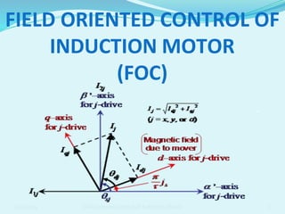
- 11. Phasor Diagrams for Induction Motor 11Field oriented control of Induction Motor12/6/2015 The steady state phasor (or vector) diagrams for an induction motor in the de-qe (synchronously rotating) reference frame are shown below:
- 12. Phasor Diagrams for Induction Motor 12Field oriented control of Induction Motor12/6/2015 An increase in Ids component will increase the flux without affecting the torque and similarly, An increase in torque component Iqs cause increase in torque without affecting the flux. This is as seen in the DC machine. As seen from the figure because of orthogonal orientation of torque (Iqs) and flux (Ids) components , they can be controlled independently. However , it is first necessary to maintain this orientation throughout the operation.
- 13. Principle of vector control 13Field oriented control of Induction Motor12/6/2015 The basic implementation of vector control is illustrated in the following block diagrams:1. Here the 3 phase currents from the input AC supply are converted into 2 phase DC quantities by using the Clark’s and Park’s transformation. 2. This is given to the machine-model for DC machine like control.
- 14. Principle of vector control 14Field oriented control of Induction Motor12/6/2015 Figure : output of machine-model to the induction machine from the controller 1. Here the output from the model is given to the controller which convert these signals back to the AC form to fed the induction motor. 1. In the controller two inverse transforms are performed: • From the synchronous d-q to the stationary d-q reference frame;
- 15. Types of vector control techniques 15Field oriented control of Induction Motor12/6/2015 There are two approaches to vector control: 1) Direct field oriented current control - here the rotation angle of the iqs vector with respect to the stator flux ψqr is being directly determined (e.g. by measuring air gap flux). 2) Indirect field oriented current control - here the rotor angle is being measured indirectly, such as by measuring slip speed. There are some other techniques as well: Sensorless vector control , stator flux oriented vector control etc.
- 16. Direct Vector Control In direct vector control the field angle is calculated by using terminal voltages and current or Hall sensors. 12/6/2015 Field oriented control of Induction Motor 16Figure :
- 17. Direct Vector Control contd… ● The principal vector control parameters, ids and iqs , which are dc values in the synchronously rotating reference frame, are converted to the stationary reference frame (using the vector rotation (VR) block) by using the unit vector cosθe and sinθe. ● These stationary reference frame control parameters ids s and iqs s are then changed to the phase current command signals, ia , ib and ic which are fed to the given type of12/6/2015 Field oriented control of Induction Motor 17
- 18. Direct Vector Control contd… 12/6/2015 Field oriented control of Induction Motor 18 A flux control loop is used to precisely control the flux. Torque control is achieved through the current iqs which is generated from the speed control loop. The torque can be negative which will result in a negative phase orientation for iqs in the phasor diagram.
- 19. Direct Vector Control contd… 12/6/2015 Field oriented control of Induction Motor 19 Figure : ds-qs and de-qe phasors showing rotor flux orientation
- 20. Direct Vector Control contd… ● Here the de-qe frame is rotating at synchronous speed ωe with respect to the stationary reference frame ds-qs, and at any point in time, the angular position of the de axis with respect to the ds axis is θe (=ωet). ● From this phasor diagram we can write: ● Therefore , 12/6/2015 Field oriented control of Induction Motor 20 Ψ Ψ Ψ
- 21. Direct Vector Control contd… 12/6/2015 Field oriented control of Induction Motor 21 ● The cosθe and sinθe signals in correct phase position are shown below: ● From the above figure : These unit vector signals, when used in the vector rotation(VR) block, cause ids to maintain orientation along the de-axis and the iqs orientation along the qe-axis. ● Finaly the above two waveforms are showing the two DC quantities Ids and Iqs which are in ohase quarature.
- 22. Advantages of vector control A few of the salient features of vector control are: ● The motor is “self-controlled” by using the unit vectors(by vector rotation block) to help control the frequency and phase. ● There is no concern about instability because limiting within the safe limit automatically limits operation to the stable region.12/6/2015 Field oriented control of Induction Motor 22
- 23. Advantages of vector control contd…. ● Transient response will be fast because torque control by iqs does not affect flux. ● Vector control allows for speed control in all four quadrants (without additional control elements) since negative torque is directly taken care of in vector control. ● Dynamic speed accuracy. ● Reduction in size of motor, cost and power consumption. 12/6/2015 Field oriented control of Induction Motor 23
- 24. Disadvantage ● With the number of steps involved in conversions from 3 to 2 phase d-q model this method is complex in nature. ● This method is impractical with complete accuracy. 12/6/2015 Field oriented control of Induction Motor 24
- 25. MATLAB Work ● The MATLAB SIMULINK modeling of Induction machine of prescribed rating is shown below: 12/6/2015 Field oriented control of Induction Motor 25 Phase conversion inside Induction machine model
- 26. MATLAB Work(PI Control) 12/6/2015 Field oriented control of Induction Motor 26 o This is the model inside the pulse generation block o Here the actual and reference speeds are compared and the error speed is used as input to the inverter.
- 27. MATLAB Work(FLC Control) 12/6/2015 Field oriented control of Induction Motor 27
- 28. Simulink results (PI) ● simulation output shows the response for the constant speed of 955rpm (100rad/s) at no load that is torque is zero. 12/6/2015 Field oriented control of Induction Motor 28
- 29. Simulink results (PI) ● For step speed of 1430rpm (150rad/s) at 0.2s. 12/6/2015 Field oriented control of Induction Motor 29
- 30. Simulink results (PI) ● For constant speed of 100 rad/s(955rpm) and step torque of 10Nm at 0.2s. 12/6/2015 Field oriented control of Induction Motor 30
- 31. Simulink results (FLC) ● The response for the constant speed of 100 rad/s(955rpm) and no load torque is as shown: 12/6/2015 Field oriented control of Induction Motor 31
- 32. Simulink results (FLC) ● The response for the step speed of 100 rad/s(1430rpm) and no load torque is as shown: 12/6/2015 Field oriented control of Induction Motor 32
- 33. Conclusion ● By using this method we obtained maximum response in minimum time. ● On comparing with scalar control method this method is fast, accurate and control variable speed of induction motor. 12/6/2015 Field oriented control of Induction Motor 33
- 34. References ● 1. Matlab mathworks.com Induction machine model. ● 2. B.K. Bose, Power Electronics and AC Drives, Prentice-Hall,’’ NJ, USA, 2002. ● 3.www.wikipedia.com ● 4. www.google.com ● 5.Nptel lectures of Induction motor Modeling. ● 6. Vas, P. ,"Vector Control of AC Machines", Oxford University Press, Oxford,1990. ● 7. Lai, Y-S.,"Modelling and Vector Control of Induction Machines- a New Unified Approach", in Conf. Rec. Power Engineering Soc. Winter Meeting, Vol. I, 1999, pp. 47-52. ● 8. H. C. Stanley, An Analysis of the Induction Motor , AIEE Transactions, Vol. 57 (Supplement), 1938, pp. 751-755. ● 9. Adel Aktaibi & Daw Ghanim,”Dynamic Simulation of a Three-Phase Induction Motor Using Matlab Simulink”,IEEE,Canada ● 10. Sandeep Goyat , Rajesh Kr. Ahuja,” SPEED CONTROL OF INDUCTION MOTOR USING VECTOR OR FIELD ORIENTED CONTROL”,IJAET, ISSN: 2231-1963 475 Vol. ,July 2012. 12/6/2015 Field oriented control of Induction Motor 34
- 35. Thank you … 12/6/2015 Field oriented control of Induction Motor 35
- 36. Questions… 12/6/2015 Field oriented control of Induction Motor 36