
Recommended
Recommended
More Related Content
What's hot
What's hot (20)
Similar to Training sap2000 linearanalysis
Similar to Training sap2000 linearanalysis (20)
Recently uploaded
Recently uploaded (20)
Training sap2000 linearanalysis
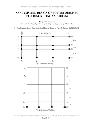
- 1. Analysis And Design Of Four Storied RC Building Using SAP2000 v14 For any suggestions and queries please write to Mr. VIJAY N. KHOSE, vijaynkhose@gmail.com Page 1 of 44 ANALYSIS AND DESIGN OF FOUR STORIED RC BUILDINGS USING SAP2000 v14 Vijay Namdev Khose Research Scholar, Department of Earthquake Engineering, IIT Roorkee Q – Analyse and design four storied building as shown in Fig.1 & 2 using SAP2000 v14 Fig.1 Plan of the building Fig. 2 Elevation of building 2 m 3 m 3 m Y4 Y3 Y2 Y1 X1 X2 X3 X4 3 Nos @ 5m C/C 3.1 3.1 3.1 3.1 1.2 Z6 Z5 Z4 Z3 Z1 Z2
- 2. Analysis And Design Of Four Storied RC Building Using SAP2000 v14 For any suggestions and queries please write to Mr. VIJAY N. KHOSE, vijaynkhose@gmail.com Page 2 of 44 Building details are as follows 1. Grade of concrete used is M 20 and grade of steel used is Fe 415. 2. Floor to floor height is 3.1 m 3. Plinth height above GL is 0.55 m. 4. Depth of Foundation is 0.65 m below GL 5. Parapet height is 1.5 m. 6. Slab Thickness is 150 mm. 7. External wall thickness is 230 mm and internal wall thickness is 150 mm. 8. Size of columns is 300mm X 450 mm and size of beams 300mm X 450 mm. 9. Live load on floor is 3kN/m2 and Live load on roof is 1.5kN/m2 . 10. Floor finishes is 1 kN/m2 and roof treatment is 1.5 kN/m2 11. Site located in Seismic Zone IV. 12. Building is resting on medium soil. 13. Take Importance Factor as 1. 14. Building frame type is Special Moment Resting Frame (SMRF). 15. Density of concrete is 25 kN/m3 and Density of masonry wall is 20 kN/m3
- 3. Analysis And Design Of Four Storied RC Building Using SAP2000 v14 For any suggestions and queries please write to Mr. VIJAY N. KHOSE, vijaynkhose@gmail.com Page 3 of 44 Step 1 Begin a New Model In this Step, the basic grid that will serve as a template for developing the model will be defined. A. Click the File menu > New Model command or the New Model button . The form shown in Fig. 3 will display. Verify that the default units are set to KN, m, C. B. The New Model form allows for the quick generation of numerous model types using parametric generation techniques. However, in this tutorial the model will be started using only the grid generation. When laying out the grid, it is important that the geometry defined accurately represents the major geometrical aspects of the model, so it is advisable to spend time carefully planning the number and spacing of the grid lines. Select the Grid Only button, and the form shown in Fig. 4 will display. C. The Quick Grid Lines form (Fig. 4) is used to specify the grids and spacing in the X, Y and Z directions. Set the number of grid lines to 4 in the X and Y direction, and to 6 in the Z directions. Type 5, 3, 3.1 into X, Y, Z directions spacing edit boxes respectively. The values specified in the First Grid Line Location area locate the origin of the grid lines; make sure that these values are all set to zero for this tutorial. Click the OK button to continue. 1. Click the Define menu > Coordinate Systems/Grids command. The Coordinate/Grid Systems form will display. Make sure that the Systems item on the Coordinate/Grid Systems form has Global highlighted and Fig.3 New Model form
- 4. Analysis And Design Of Four Storied RC Building Using SAP2000 v14 For any suggestions and queries please write to Mr. VIJAY N. KHOSE, vijaynkhose@gmail.com Page 4 of 44 Fig. 4 Quick Grid lines form Fig. 5 Define Grid Data form Fig. 6 SAP 2000 Windows
- 5. Analysis And Design Of Four Storied RC Building Using SAP2000 v14 For any suggestions and queries please write to Mr. VIJAY N. KHOSE, vijaynkhose@gmail.com Page 5 of 44 click the Modify/Show System button. The Define Grid Data form (Fig. 5) will display. 2. The Define grid data form is used to specify the irregular spacing in the X, Y and Z directions. Set the Display Grid as to spacing. 3. In Y Grid Data set spacing as 2 for Grid ID 2 and in Z Grid Data set it to 1.2 for z1 Grid ID. 4. Click the OK button to close the Define Grid Data form. D. Click the OK button to close the Coordinate/Grid Systems form, and Fig. 6 will appear. The grids appear in two view windows tiled vertically, an X-Y “Plan” View on the left and a 3-D View on the right, as shown in Fig. 6. The number of view windows may be changed by selecting the Options menu > Windows command. Notice that the “Plan” view is active in Fig 6. When the window is active, the display title bar is highlighted. Set a view active by clicking anywhere in the view window. Note that the Global Axes are displayed as well, and that Z positive is in the “up” direction. When SAP2000 refers to the direction of gravity, this is in the negative Z direction, or “down”. Step 2 Define Material Use the Define menu > Materials command to add, modify, or delete a material property definition. The material property definitions are then used in defining the structural objects (frame sections, cable sections, tendon sections, area sections, solid properties). A. Click the Define menu > Materials command, the Define Material form (Fig. 7) will display. Fig. 7 Define Materials form
- 6. Analysis And Design Of Four Storied RC Building Using SAP2000 v14 For any suggestions and queries please write to Mr. VIJAY N. KHOSE, vijaynkhose@gmail.com Page 6 of 44 Highlight a 4000Psi in the Materials display list. Then Click the Modify/Show Material button, the form shown in Fig. 8 will display. B. In Material Name and display color edit box, type M20 and in Material Type select concrete from drop down list. C. Set Weight per unit Volume as 25. Set Modulus of Elasticity to 22360679.774 ( ckf5000 as per IS 456). Set Poisson’s Ratio to 0.15. Set Specified Concrete Compressive Strength to 20000 and then click OK button. D. Highlight a A992fy50 in the Materials display list. Then Click on Modify/Show Material button, the form shown in Fig. 9 will display. E. In Material Name and display color edit box, type Fe415 and in Material Type select Rebar from drop down list. F. Set Minimum yield stress, fy, Minimum tensile stress, fu , Expected yield stress, fye and Expected tensile stress, fue to 415000, 498000, 518750 and 622500. Click OK buttons on Material Property Data form and Add materials form to exit all forms. Fig. 8 Material Property Data form -Concrete Fig. 9 Material Property Data form -Rebar
- 7. Analysis And Design Of Four Storied RC Building Using SAP2000 v14 For any suggestions and queries please write to Mr. VIJAY N. KHOSE, vijaynkhose@gmail.com Page 7 of 44 Step 3 Define Frame Section Defining a frame section makes the section available for assignment to selected frame objects. The Define menu > Frame Sections command can be used to (a) import sections from predefined databases, (b) define frame section properties on the basis of their dimensions, (c) review and modify section properties, and (d) delete section properties. A. Click the Define menu > Section Properties > Frame Sections command, which will display the Frame Properties form (Fig. 10). B. Click the Add New Property button, which will display form shown in Fig. 11 C. In Frame Section Property Type select Concrete from drop down list and click the Rectangular button, which will display from shown in Fig. 12. 1. In Section Name Area, Type C-300X450. 2. In Depth and Width edit box, Type 0.45 and 0.3 respectively. D. Click the Concrete Reinforcement button, Reinforcement data form (Fig. 13) will appear. 1. In Rebar Material Area, Select Fe415 from list as a Rebar Material of Fig. 10 Frame Properties form Fig. 12 Rectangular Section formFig. 11 Add Frame Section Property form
- 8. Analysis And Design Of Four Storied RC Building Using SAP2000 v14 For any suggestions and queries please write to Mr. VIJAY N. KHOSE, vijaynkhose@gmail.com Page 8 of 44 Longitudinal Bars and Confinement Bars (Ties). 2. In Design Type Area, Select Column (P-M2-M3Design) option. 3. In Configuration of reinforcement area, select Rectangular. 4. In Longitudinal Bars - Rectangular Configuration area, Type 0.05 in Cover to for confinement bars edit box. 5. In Confinement Bars Area, Select 8d from drop down list as Confinement Bar Size; Type 0.2 in Longitudinal Spacing of Confinement Bars edit box and Type 2 in Number of Confinement Bars in 3-dir and 2-dir. 6. In Set Check/ Design Area, select Reinforcement to be Designed. 7. Click OK buttons on Reinforcement Data form and Rectangular section form. E. Click the Add New Property button, which will display form shown in Fig. 11. F. Make sure that in Frame Section Property Type, Concrete is selected and click the Rectangular button, which will display from shown in Fig. 12. 1. In Section Name Area, Type B-300X450. 2. In Depth and Width edit box, Type 0.45 and 0.3 respectively. Fig. 13Reinforcement Data form for Column Fig. 14Reinforcement Data form for Beam
- 9. Analysis And Design Of Four Storied RC Building Using SAP2000 v14 For any suggestions and queries please write to Mr. VIJAY N. KHOSE, vijaynkhose@gmail.com Page 9 of 44 G. Click the Concrete Reinforcement button, Reinforcement data form (Fig. 13) will appear. 1. In Rebar Material Area, Select Fe415 from list as a rebar material of Longitudinal Bars and Confinement Bars (Ties). 2. In Design Type Area, Select Beam (M3Design only) option, which will display reinforcement data form (Fig.14) for beam. 3. In Concrete Cover to Rebar Center Area, Type 0.03 Top and Bottom edit box. 4. Click the OK buttons on Reinforcement Data form, Rectangular section form and frame properties form. Step 4 Add Frame Objects In this Step, Frame objects with the associated column and beam sections list are drawn using the grids and snap-to options, and generated using Edit menu commands. Draw Frame Objects (XZ Plane) Make sure that the X-Z Plane @ Y= 0 views is active (see Step1-D for directions on how to make a view active). This view should be in the left window. Also check that the Snap to Points and Grid Intersections command is active. This will assist in accurately positioning the frame objects. This command is active when its associated button is depressed. Alternatively, use the Draw menu > Snap to > Points and Grid Intersections command. By default, this command is active. A. Click the View menu > Set 2D View command. B. In the Set 2D View form click on the X-Z plane option. Type 0 into the Y = edit box to display the Side view at Y = 0, and click OK. C. Click the Draw Frame/Cable/Tendon button or use the Draw menu > Draw Frame/Cable/Tendon command. If you accessed the Draw Frame/Cable/Tendon command via the Draw menu, the Draw Frame/Cable/Tendon button will depress verifying your command selection. The Properties of Object pop-up form for frames will appear as shown in Fig.15.
- 10. Analysis And Design Of Four Storied RC Building Using SAP2000 v14 For any suggestions and queries please write to Mr. VIJAY N. KHOSE, vijaynkhose@gmail.com Page 10 of 44 If the Properties of Object form is covering any part of the model in either view, click on the title bar and drag it out of the way. D. Click in the Section drop-down list on the Properties of Object form and scroll down to C- 300X450. Single click on it to assign the auto select list C-300X450 to the members you will draw. E. To draw the columns, left click once in the X-Z Plane view at the X-Z origin, and then go on clicking at the nodes (X=0, Z=1.2), (X=0, Z=4.3), (X=0, Z=7.4), (X=0, Z=10.5) and (X=0, Z=13.6) i.e. nodes along the vertical grid line X =0. The cursor location is indicated in the lower right-hand corner of the interface. A frame lines should appear in both views (Side and 3D). After clicking to define the end point of the column, a right click will “lift the pen” so you will no longer be actively drawing, but will leave the Draw Frame/Cable/Tendon command active so that you may add additional objects. If you have made a mistake while drawing this object, click the Select Object button, to leave the Draw mode and go to the Select mode. Then click the Edit menu > Undo Frame Add command, and repeat Items C-D. F. Repeat Item E to draw additional columns along the Grid line X=5, X=10 and X=15. These members form the columns of XZ frame at Y = 0. Right click to stop drawing. G. Click in the Section drop-down list on the Properties of Object form (Fig. 15) and scroll down to B-300X450. Single click on it to assign the auto select list B- 300X450 to the members you will draw. H. Repeat Item E to draw beams along grid line Z=1.2, Z=4.3, Z=7.4, Z=10.5 and Z= 13.6. These members form the complete XZ frame at Y = 0. I. Click the Select Object button, or Press the Esc key on the key-board to exit the Draw Frame/Cable/Tendon command. Fig. 15 Properties of Objects
- 11. Analysis And Design Of Four Storied RC Building Using SAP2000 v14 For any suggestions and queries please write to Mr. VIJAY N. KHOSE, vijaynkhose@gmail.com Page 11 of 44 Add Restraints In this step, supports for the frame are defined. Make sure that the X-Y Plane @ Z=0 view is active, and that the program is in the Select mode. A. Select the support nodes i.e. nodes at Z=0. B. Click the Assign menu > Joint > Restraints command to bring up the Joint Restraints form (Fig. 16). C. Click the Fixed support button to assign restraints in the Translation and Rotation in 1, 2 and 3 directions. Click OK to accept the changes. Modify Column Orientation To better view the column orientation, click the Set Display Options button. When the form (Fig. 18) appears, check the Fill Objects and Extrude view check box and the Apply to All Window check box, as shown in Fig.18. A. Select all the columns along the grid line X=0 and X =15. B. Click the Assign menu > Frame > Local Axes command to access the Frame Local Axis form (Fig. 17). Fig. 16 Joint restraints form Fig. 17 Frame Local Axis Form Fig. 18 Display Options for Active Window
- 12. Analysis And Design Of Four Storied RC Building Using SAP2000 v14 For any suggestions and queries please write to Mr. VIJAY N. KHOSE, vijaynkhose@gmail.com Page 12 of 44 C. Type 90 in Angle in degrees edit box. Click OK to accept changes. Replicate Objects Make sure that the program is in the Select mode. A. Select the complete XZ plane frame at Y=0 by left clicking directly on the members, or left clicking to the right of the object, holding the left mouse button down, and dragging the mouse across the member. See Fig. 19 for selection options. B. Click the Edit menu > Replicate command to bring up the form shown in Fig. 20. C. On the Linear tab, type 3 into the dy edit box. Type 1 in the Number edit box. Click the OK button. D. Repeat Item A-B. Fig. 19 Graphical selection options
- 13. Analysis And Design Of Four Storied RC Building Using SAP2000 v14 For any suggestions and queries please write to Mr. VIJAY N. KHOSE, vijaynkhose@gmail.com Page 13 of 44 E. On the Linear tab, type 5 into the dy edit box. Type 1 in the Number edit box. Click the OK button. F. Again repeat Item A-B G. On the Linear tab, type 8 into the dy edit box. Type 1 in the Number edit box. Click the OK button. Draw Frame Objects (YZ Plane) Make sure that the Y-Z Plane @ X= 0 view is active Or Click the View menu > Set 2D View command. In the Set 2D View form click on the Y-Z plane option. Type 0 into the X = edit box to display the Side view at X = 0, and click OK. A. Click the Draw Frame/Cable/Tendon button or use the Draw menu > Draw Frame/Cable/Tendon command. The Properties of Object pop-up form for frames will appear as shown in Fig.15. B. Click in the Section drop-down list on the Properties of Object form (Fig. 15) and scroll down to B-300X450. Single click on it to assign the auto select list B- 300X450 to the members you will draw. C. Draw beams along Grid line Z=1.2, Z=4.3, Z=7.4, Z=10.5 and Z=13.6. These members form the complete YZ frame at X = 0. Right click to stop drawing. D. Click the Select Object button, or Press the Esc key on the key-board to exit the Draw Frame/Cable/Tendon command. Replicate Objects Make sure that the program is in the Select mode and Y-Z Plane @ X= 0 views is active. A. Select all the beams in YZ plane frame at X=0. B. Click the Edit menu > Replicate command to bring up the form shown in Fig. 20. C. On the Linear tab, type 5 into the dx edit box. Type 3 in the Number edit box. D. Click the OK button. Fig. 20 Replicate form
- 14. Analysis And Design Of Four Storied RC Building Using SAP2000 v14 For any suggestions and queries please write to Mr. VIJAY N. KHOSE, vijaynkhose@gmail.com Page 14 of 44 Step 5 Define Load Patterns The loads used in this problem consist of Dead, Dead Wall, Dead Slab, Dead FF (Floor finish), Dead RT (Roof treatment), Live and Live Roof loads acting in the gravity direction. A. Click the Define menu > Load Patterns command to bring up the Define Load Patterns form (Fig. 21). Note there is a single default load case defined, which is a Dead Load case with self-weight (DEAD). Note that the self-weight multiplier is set to 1 for the default case. This indicates that this load pattern will automatically include 1.0 times the self-weight of all members. In SAP2000, both Load Patterns and Load Cases exist, and they may be different. However, the program automatically creates a corresponding Load case when a load pattern is defined, and the load cases are available for review at the time the analysis is run. B. Click in the edit box for the Load Pattern Name column. Type the name of the new load pattern, DEAD Wall. Select a Type of load from the drop-down list; in this case, select SUPER DEAD. Make sure that the Self Weight multiplier is set to zero. Click the Add New Load Pattern button to add the Dead Wall load to the load list. C. Repeat item B, to add Dead Slab, Dead FF, Dead RT load cases. D. Type the name of the new load pattern, LIVE. Select LIVE, a Type of load from the drop-down list. Make sure that the Self Weight Multiplier is set to zero. Click the Add New Load Pattern button to add the Live load to the load list. E. Type the name of the new load pattern, LIVE ROOF. Select ROOF LIVE, a Type of load from the drop-down list. Make sure that the Self Weight Multiplier is set to zero. Click the Add New Load Pattern button to add the Live load to the load list. Fig. 21 Define load Patterns form
- 15. Analysis And Design Of Four Storied RC Building Using SAP2000 v14 For any suggestions and queries please write to Mr. VIJAY N. KHOSE, vijaynkhose@gmail.com Page 15 of 44 F. The Define Loads form should now appear as shown in Fig. 22. Click the OK button in that form to accept the newly defined static load cases. Step 6 Assign Gravity Loads In this Step, the Dead and Live loads will be applied to the model. Assign DEAD WALL load Make sure that the X-Y Plane @ Z=1.2 view is active, and that the program is in the select mode. A. Select the all external walls in X-Y Plane at level Z=1.2, Z= 4.3, Z=7.4 & Z=10.5. If you make a mistake in selecting, press the Clear Selection button, and try again. Use the Move Up in list and Move Down in List buttons to change floor level. B. Click the Assign menu > Frame Loads > Distributed command. This brings up the Frame Distributed Loads form (Fig. 23). 1. Select DEAD WALL from the Load Case Name drop-down list. New Load Pattern can be added by clicking New Load Pattern button, if required. 2. In Units, Verify that the KN, m, C option is selected. 3. In the Load Type and Direction area, verify that the Forces option is selected and that the Gravity direction is selected. 4. In the Options, select the Replace Existing Loads Option. Fig. 22 Define load Patterns form
- 16. Analysis And Design Of Four Storied RC Building Using SAP2000 v14 For any suggestions and queries please write to Mr. VIJAY N. KHOSE, vijaynkhose@gmail.com Page 16 of 44 5. Type 12.19 (value of external wall load intensity) in the Uniform Load edit box. Remember that the Gravity Direction is in the negative Global Z direction. 6. In the Trapezoidal loads area, verify that in all Load edit boxes values are zero. 7. Click the OK button to accept the DEAD WALL load. C. Select all internal walls in X-Y Plane at level Z=1.2, Z= 4.3, Z=7.4 & Z=10.5. D. Click the Assign menu > Frame Loads > Distributed command. 1. In Load Case Name, Verify that Dead Wall is selected. 2. In the Options, select the Replace Existing Loads Option. 3. Type 7.95 (value of internal wall load intensity) in the Uniform Load edit box 4. In the Trapezoidal loads area, verify that in all Load edit boxes values are zero. 5. Click the OK button to accept the Dead Wall load. E. Make sure that the X-Y Plane @ Z=13.6 views is active, and that the program is in the Select mode. Select all external walls. F. Click the Assign menu > Frame Loads > Distributed command. 1. In Load Case Name, Verify that DEAD WALL is selected. 2. In the Options, select the Replace Existing Loads Option. 3. Type 6.90 (value of parapet wall load intensity) in the Uniform Load edit box 4. In the Trapezoidal loads area, verify that in all Load edit boxes values are zero. 5. Click the OK button to accept the DEAD WALL load. Fig. 23 Frame Distributed Loads form
- 17. Analysis And Design Of Four Storied RC Building Using SAP2000 v14 For any suggestions and queries please write to Mr. VIJAY N. KHOSE, vijaynkhose@gmail.com Page 17 of 44 Assign DEAD SLAB load In this tutorial Slab load is transferred to adjacent beams and Rigid Diaphragm is assigned to simulate the in-plane slab rigidity. Yield line pattern for slab load is shown in Fig.24. Make sure that the X-Y Plane @ Z=4.3 view is active, and that the program is in the select mode. A. Select the all beams in X-Y Plane along line Y=0, Y=3, Y=5 and Y=8 (i.e. beams along Y1, Y2, Y3 and Y4 in Fig. 24) at level Z= 4.3, Z=7.4, Z=10.5 & Z=13.6). Use the Move Up in list and Move Down in List buttons to change floor level. B. Click the Assign menu > Frame Loads > Distributed command. 1. Select DEAD SLAB from the Load Case Name drop-down list. 2. In the Options, select the Replace Existing Loads Option. 3. In the Trapezoidal loads area, select the Absolute Distance From End I option. a. In Trapezoidal loads area, type 0 in first Distance and Load edit boxes. b. Type 1.5 in second Distance edit box and type 5.625 in second Load edit box. X4X3X2X1 Y1 Y3 Y2 Y4 Fig. 24 Yield line pattern for slab load
- 18. Analysis And Design Of Four Storied RC Building Using SAP2000 v14 For any suggestions and queries please write to Mr. VIJAY N. KHOSE, vijaynkhose@gmail.com Page 18 of 44 c. Type 3.5 in third Distance edit box and type 5.625 in third Load edit box. d. Type 5 in fourth Distance edit box and type 0 in fourth Load edit box 4. In the Uniform load area, Type 0 in Load edit box. 5. Click the OK button to accept the DEAD SLAB load. C. Select the all beams in X-Y Plane along line Y=3 and Y=5 (i.e. beams alongY2 & Y3 in Fig. 22) at level Z= 4.3, Z=7.4, Z=10.5 & Z=13.6). D. Click the Assign menu > Frame Loads > Distributed command. 1. In Load Case Name, Verify that DEAD SLAB is selected. 2. In the Options, select the Add to Existing Loads Option. 3. In the Trapezoidal loads area, Type 0 in all Load edit boxes. 4. In the Uniform load area, Type 3.75 in Load edit box. 5. Click the OK button to accept the DEAD SLAB load. E. Select the beams having 3m length in X-Y Plane along line X=0, X=5, X=10 and X=15(i.e. beams along X1, X2, X3 and X4 in Fig. 24) at level Z= 4.3, Z=7.4, Z=10.5 & Z=13.6). F. Click the Assign menu > Frame Loads > Distributed command. 1. Select DEAD SLAB from the Load Case Name drop-down list. 2. In the Options, select the Replace Existing Loads Option. 3. In the Trapezoidal loads area, select the Absolute Distance From End I option. a. In Trapezoidal loads area, type 0 in first Distance and Load edit boxes. b. Type 1.5 in second Distance edit box and type 5.625 in second Load edit box. c. Type 1.5 in third Distance edit box and type 5.625 in third Load edit box. d. Type 3 in fourth Distance edit box and type 0 in fourth Load edit box. 4. In the Uniform load area, Type 0 in Load edit box.
- 19. Analysis And Design Of Four Storied RC Building Using SAP2000 v14 For any suggestions and queries please write to Mr. VIJAY N. KHOSE, vijaynkhose@gmail.com Page 19 of 44 5. Click the OK button to accept the DEAD SLAB load. G. Select the beams having 3m length in X-Y Plane along line X=5 & X=10 (i.e. beams along X2 and X3 in Fig. 24) at level Z= 4.3, Z=7.4, Z=10.5 & Z=13.6). H. Click the Assign menu > Frame Loads > Distributed command. 1. Select DEAD SLAB from the Load Case Name drop-down list. 2. In the Options, select the Add to Existing Loads Option. 3. In the Trapezoidal loads area, select the Absolute Distance From End I option. a. In Trapezoidal loads area, type 0 in first Distance and Load edit boxes. b. Type 1.5 in second Distance edit box and type 5.625 in second Load edit box. c. Type 1.5 in third Distance edit box and type 5.625 in third Load edit box. d. Type 3 in fourth Distance edit box and type 0 in fourth Load edit box. 4. In the Uniform load area, Type 0 in Load edit box. 5. Click the OK button to accept the Dead Slab load. Assign DEAD FF (Floor Finish) load Make sure that the X-Y Plane @ Z=4.3 view is active, and that the program is in the select mode. A. Select the all beams in X-Y Plane along line Y=0, Y=3, Y=5 and Y=8 (i.e. beams along Y1, Y2, Y3 and Y4 in Fig. 24) at level Z= 4.3, Z=7.4and Z=10.5). B. Click the Assign menu > Frame Loads > Distributed command. 1. Select DEAD FF from the Load Case Name drop-down list. 2. In Units, Verify that the KN, m, C option is selected. 3. In the Load Type and Direction area, verify that the Forces option is selected and that the Gravity direction is selected. 4. In the Options, select the Replace Existing Loads Option.
- 20. Analysis And Design Of Four Storied RC Building Using SAP2000 v14 For any suggestions and queries please write to Mr. VIJAY N. KHOSE, vijaynkhose@gmail.com Page 20 of 44 5. In the Trapezoidal loads area, select the Absolute Distance From End I option. a. In Trapezoidal loads area, type 0 in first Distance and Load edit boxes. b. Type 1.5 in second Distance edit box and type1.5 in second Load edit box. c. Type 3.5 in third Distance edit box and type1.5 in third Load edit box. d. Type 5 in fourth Distance edit box and type 0 in fourth Load edit box 6. In the Uniform load area, Type 0 in Load edit box. 7. Click the OK button to accept the DEAD FF load. C. Select the all beams in X-Y Plane along line Y=3 and Y=5 (i.e. beams along Y2 and Y3 in Fig. 24) at level Z= 4.3, Z=7.4and Z=10.5). D. Click the Assign menu > Frame Loads > Distributed command. 1. In Load Case Name, Verify that DEAD FF is selected. 2. In the Options, select the Add to Existing Loads Option. 3. In the Trapezoidal loads area, Type 0 in all Load edit boxes. 4. In the Uniform load area, Type 1 in Load edit box. 5. Click the OK button to accept the DEAD FF load. E. Select the beams having 3m length in X-Y Plane along line X=0, X=5, X=10 and X=15 (i.e. beams along X1, X2, X3 and X4 in Fig. 24) at level Z= 4.3, Z=7.4and Z=10.5). F. Click the Assign menu > Frame Distributed command. 1. Select DEAD FF from the Load Case Name drop-down list. 2. In the Options, select the Replace Existing Loads Option. 3. In the Trapezoidal loads area, select the Absolute Distance From End I option. a. In Trapezoidal loads area, type 0 in first Distance and Load edit boxes. b. Type 1.5 in second Distance edit box and type 1.5 in second Load edit box.
- 21. Analysis And Design Of Four Storied RC Building Using SAP2000 v14 For any suggestions and queries please write to Mr. VIJAY N. KHOSE, vijaynkhose@gmail.com Page 21 of 44 c. Type 1.5 in third Distance edit box and type 1.5 in third Load edit box. d. Type 3 in fourth Distance edit box and type 0 in fourth Load edit box. 4. In the Uniform load area, Type 0 in Load edit box. 5. Click the OK button to accept the DEAD FF load. G. Select the beams having 3m length in X-Y Plane along line X=5 & X=10 (i.e. beams along X2 and X3 in Fig. 24) at level Z= 4.3, Z=7.4and Z=10.5). H. Click the Assign menu > Frame Loads > Distributed command. 1. Select DEAD FF from the Load Case Name drop-down list. 2. In the Options, select the Add to Existing Loads Option. 3. In the Trapezoidal loads area, select the Absolute Distance From End I option. a. In Trapezoidal loads area, type 0 in first Distance and Load edit boxes. b. Type 1.5 in second Distance edit box and type 1.5 in second Load edit box. c. Type 1.5 in third Distance edit box and type 1.5 in third Load edit box. d. Type 3 in fourth Distance edit box and type 0 in fourth Load edit box. 4. In the Uniform load area, Type 0 in Load edit box. 5. Click the OK button to accept the DEAD FF load. Assign DEAD RT (Roof Treatment) load Make sure that the X-Y Plane @ Z=13.6 views is active, and that the program is in the select mode. A. Select the all beams in X-Y Plane along line Y=0, Y=3, Y=5 and Y=8(i.e. beams along Y1, Y2, Y3 and Y4 in Fig. 24). B. Click the Assign menu > Frame Loads > Distributed command. 1. Select DEAD RT from the Load Case Name drop-down list. 2. In Units, Verify that the KN, m, C option is selected.
- 22. Analysis And Design Of Four Storied RC Building Using SAP2000 v14 For any suggestions and queries please write to Mr. VIJAY N. KHOSE, vijaynkhose@gmail.com Page 22 of 44 3. In the Load Type and Direction area, verify that the Forces option is selected and that the Gravity direction is selected. 4. In the Options, select the Replace Existing Loads Option. 5. In the Trapezoidal loads area, select the Absolute Distance From End I option. a. In Trapezoidal loads area, type 0 in first Distance and Load edit boxes. b. Type 1.5 in second Distance edit box and type2.25 in second Load edit box. c. Type 3.5 in third Distance edit box and type2.25 in third Load edit box. d. Type 5 in fourth Distance edit box and type 0 in fourth Load edit box 6. In the Uniform load area, Type 0 in Load edit box. 7. Click the OK button to accept the Dead RT load. C. Select the all beams in X-Y Plane along line Y=3 and Y=5 (i.e. beams along Y2, and Y3 in Fig. 24). D. Click the Assign menu > Frame Loads > Distributed command. 1. In Load Case Name, Verify that DEAD RT is selected. 2. In the Options, select the Add to Existing Loads Option. 3. In the Trapezoidal loads area, Type 0 in all Load edit boxes. 4. In the Uniform load area, Type 1.5 in Load edit box. 5. Click the OK button to accept the DEAD RT load. E. Select the beams having 3m length in X-Y Plane along line X=0, X=5, X=10 and X=15 (i.e. beams along X1, X2, X3 and X4 in Fig. 24). F. Click the Assign menu > Frame Loads > Distributed command. 1. Select DEAD RT from the Load Case Name drop-down list. 2. In the Options, select the Replace Existing Loads Option. 3. In the Trapezoidal loads area, select the Absolute Distance From End I option.
- 23. Analysis And Design Of Four Storied RC Building Using SAP2000 v14 For any suggestions and queries please write to Mr. VIJAY N. KHOSE, vijaynkhose@gmail.com Page 23 of 44 a. In Trapezoidal loads area, type 0 in first Distance and Load edit boxes. b. Type 1.5 in second Distance edit box and type 2.25 in second Load edit box. c. Type 1.5 in third Distance edit box and type 2.25 in third Load edit box. d. Type 3 in fourth Distance edit box and type 0 in fourth Load edit box. 4. In the Uniform load area, Type 0 in Load edit box. 5. Click the OK button to accept the DEAD RT load. G. Select the beams having 3m length in X-Y Plane along line X=5 & X=10 (i.e. beams along X2 and X3 in Fig. 24). H. Click the Assign menu > Frame Loads > Distributed command. 1. Select DEAD RT from the Load Case Name drop-down list. 2. In the Options, select the Add to Existing Loads Option. 3. In the Trapezoidal loads area, select the Absolute Distance From End I option. a. In Trapezoidal loads area, type 0 in first Distance and Load edit boxes. b. Type 1.5 in second Distance edit box and type 2.25 in second Load edit box. c. Type 1.5 in third Distance edit box and type 2.25 in third Load edit box. d. Type 3 in fourth Distance edit box and type 0 in fourth Load edit box. 4. In the Uniform load area, Type 0 in Load edit box. 5. Click the OK button to accept the Dead RT load.
- 24. Analysis And Design Of Four Storied RC Building Using SAP2000 v14 For any suggestions and queries please write to Mr. VIJAY N. KHOSE, vijaynkhose@gmail.com Page 24 of 44 Assign LIVE Load A. Select the all beams in X-Y Plane along line Y=0, Y=3, Y=5 and Y=8 at level Z= 4.3, Z=7.4 & Z=10.5 (i.e. beams along Y1, Y2, Y3 and Y4 in Fig. 24). B. Click the Assign menu > Frame Loads > Distributed command. 1. Select LIVE from the Load Case Name drop-down list. 2. In Units, Verify that the KN, m, C option is selected. 3. In the Load Type and Direction area, verify that the Forces option is selected and that the Gravity direction is selected. 4. In the Options, select the Replace Existing Loads Option. 5. In the Trapezoidal loads area, select the Absolute Distance From End I option. a. In Trapezoidal loads area, type 0 in first Distance and Load edit boxes. b. Type 1.5 in second Distance edit box and type 4.5 in second Load edit box. c. Type 3.5 in third Distance edit box and type 4.5 in third Load edit box. d. Type 5 in fourth Distance edit box and type 0 in fourth Load edit box 6. In the Uniform load area, Type 0 in Load edit box. 7. Click the OK button to accept the LIVE load. I. Select the all beams in X-Y Plane along line Y=3 and Y=5 at level Z= 4.3, Z=7.4 & Z=10.5 (i.e. beams along Y2 and Y3 in Fig. 24). J. Click the Assign menu > Frame Loads > Distributed command. 1. In Load Case Name, Verify that LIVE is selected. 2. In the Options, select the Add to Existing Loads Option. 3. In the Trapezoidal loads area, Type 0 in all Load edit boxes. 4. In the Uniform load area, Type 3 in Load edit box. 5. Click the OK button to accept the LIVE load.
- 25. Analysis And Design Of Four Storied RC Building Using SAP2000 v14 For any suggestions and queries please write to Mr. VIJAY N. KHOSE, vijaynkhose@gmail.com Page 25 of 44 K. Select the beams having 3m length in X-Y Plane along line X=0, X=5, X=10 and X=15 at level Z= 4.3, Z=7.4 & Z=10.5 (i.e. beams along X1, X2, X3 and X4 in Fig. 24). L. Click the Assign menu > Frame Loads > Distributed command. 1. Select Live from the Load Case Name drop-down list. 2. In the Options, select the Replace Existing Loads Option. 3. In the Trapezoidal loads area, select the Absolute Distance From End I option. a. In Trapezoidal loads area, type 0 in first Distance and Load edit boxes. b. Type 1.5 in second Distance edit box and type 4.5 in second Load edit box. c. Type 1.5 in third Distance edit box and type 4.5 in third Load edit box. d. Type 3 in fourth Distance edit box and type 0 in fourth Load edit box. 4. In the Uniform load area, Type 0 in Load edit box. 5. Click the OK button to accept the LIVE load. M. Select the beams having 3m length in X-Y Plane along line X=5 & X=10 at level Z= 4.3, Z=7.4 & Z=10.5 (i.e. beams along X2 and X3 in Fig. 24). N. Click the Assign menu > Frame Loads > Distributed command. 1. Select Live from the Load Case Name drop-down list. 2. In the Options, select the Add to Existing Loads Option. 3. In the Trapezoidal loads area, select the Absolute Distance From End I option. a. In Trapezoidal loads area, type 0 in first Distance and Load edit boxes. b. Type 1.5 in second Distance edit box and type 4.5 in second Load edit box. c. Type 1.5 in third Distance edit box and type 4.5 in third Load edit box.
- 26. Analysis And Design Of Four Storied RC Building Using SAP2000 v14 For any suggestions and queries please write to Mr. VIJAY N. KHOSE, vijaynkhose@gmail.com Page 26 of 44 d. Type 3 in fourth Distance edit box and type 0 in fourth Load edit box. 4. In the Uniform load area, Type 0 in Load edit box. 5. Click the OK button to accept the LIVE load. Assign LIVE ROOF load Make sure that the X-Y Plane @ Z=13.6 views is active, and that the program is in the select mode. A. Select the all beams in X-Y Plane along line Y=0, Y=3, Y=5 and Y=8. B. Click the Assign menu > Frame Loads > Distributed command. a. Select LIVE ROOF from the Load Case Name drop-down list. b. In Units, Verify that the KN, m, C option is selected. c. In the Load Type and Direction area, verify that the Forces option is selected and that the Gravity direction is selected. d. In the Options, select the Replace Existing Loads Option. e. In the Trapezoidal loads area, select the Absolute Distance From End I option. 1. In Trapezoidal loads area, type 0 in first Distance and Load edit boxes. 2. Type 1.5 in second Distance edit box and type 2.25 in second Load edit box. 3. Type 3.5 in third Distance edit box and type 2.25 in third Load edit box. 4. Type 5 in fourth Distance edit box and type 0 in fourth Load edit box f. In the Uniform load area, Type 0 in Load edit box. g. Click the OK button to accept the Live Roof load. C. Select the all beams in X-Y Plane along line Y=3 and Y=5 D. Click the Assign menu > Frame Loads > Distributed command. a. In Load Case Name, Verify that Live Roof is selected. b. In the Options, select the Add to Existing Loads Option.
- 27. Analysis And Design Of Four Storied RC Building Using SAP2000 v14 For any suggestions and queries please write to Mr. VIJAY N. KHOSE, vijaynkhose@gmail.com Page 27 of 44 c. In the Trapezoidal loads area, Type 0 in all Load edit boxes. d. In the Uniform load area, Type 1.5 in Load edit box. e. Click the OK button to accept the Live Roof load. E. Select the beams having 3m length in X-Y Plane along line X=0, X=5, X=10 and X=15 F. Click the Assign menu > Frame Loads > Distributed command. a. Select LIVE ROOF from the Load Case Name drop-down list. b. In the Options, select the Replace Existing Loads Option. c. In the Trapezoidal loads area, select the Absolute Distance From End I option. 1. In Trapezoidal loads area, type 0 in first Distance and Load edit boxes. 2. Type 1.5 in second Distance edit box and type 2.25 in second Load edit box. 3. Type 1.5 in third Distance edit box and type 2.25 in third Load edit box. 4. Type 3 in fourth Distance edit box and type 0 in fourth Load edit box. d. In the Uniform load area, Type 0 in Load edit box. e. Click the OK button to accept the LIVE ROOF load. G. Select the all beams in X-Y Plane along line X=5 & X=10 H. Click the Assign menu > Frame Loads > Distributed command. a. Select LIVE ROOF from the Load Case Name drop-down list. b. In the Options, select the Add to Existing Loads Option. c. In the Trapezoidal loads area, select the Absolute Distance From End I option. 1. In Trapezoidal loads area, type 0 in first Distance and Load edit boxes. 2. Type 1.5 in second Distance edit box and type 2.25 in second Load edit box.
- 28. Analysis And Design Of Four Storied RC Building Using SAP2000 v14 For any suggestions and queries please write to Mr. VIJAY N. KHOSE, vijaynkhose@gmail.com Page 28 of 44 3. Type 1.5 in third Distance edit box and type 2.25 in third Load edit box. 4. Types 3 in fourth Distance edit box and type 0 in fourth Load edit box. d. In the Uniform load area, Type 0 in Load edit box. e. Click the OK button to accept the LIVE ROOF load. Step 7 Assign Rigid Diaphragm Make sure that the X-Y Plane @ Z=4.3 view is active, and that the program is in the select mode. A. Select all the nodes at Z= 4.3, Z=7.4, Z=10.5 & Z=13.6 level. B. Click the Assign menu > Joint >Constraints command. This brings up the Assign/Define Constraint form (Fig. 25). C. In the Choose Constraint Type to Add area, click the drop-down list and select Diaphragm. D. Click the Add New Constraint button, which will display Diaphragm Constraint form (Fig. 26). E. Type Floor Diaphragm in the Constraint Name edit box. F. Verify that the Z Axis option is selected in Fig. 25 Assign /Define Constraints form Fig. 26 Assign/Define Constraints form
- 29. Analysis And Design Of Four Storied RC Building Using SAP2000 v14 For any suggestions and queries please write to Mr. VIJAY N. KHOSE, vijaynkhose@gmail.com Page 29 of 44 the Constraint Axis area. G. Check Assign a different diaphragm constraint to each different selected Z level box. H. Click the OK buttons on the Diaphragm Constraint and the Assign/Define constraints forms to exit all forms. Step 8 Define Response Spectrum Function. A response-spectrum function is simply a list of period versus spectral-acceleration values. In SAP2000, the acceleration values in the function are assumed to be normalized; that is, the functions themselves are not assumed to have units. Instead, the units are associated with a scale factor that multiplies the function and that is specified when the response-spectrum analysis case is defined. A. Click the Define menu > Functions > Response Spectrum Functions command, which will display Define Response Spectrum Function form (Fig.27). B. In the Choose the Function Type to Add area, Select Spectrum from File from drop-down list. C. Click the Add New Function button, which will display Response Spectrum function Definition form (Fig. 28). 1. In Function Name edit box, type RES IS 1893 II. 2. In Function Fig. 27 Define Response Spectrum Functions Fig. 28 Response Spectrum Function Definition form
- 30. Analysis And Design Of Four Storied RC Building Using SAP2000 v14 For any suggestions and queries please write to Mr. VIJAY N. KHOSE, vijaynkhose@gmail.com Page 30 of 44 Damping Ratio area, type 0.05. 3. In Function File area, click the Browse button in this area and pick the text file that includes the response spectrum data (Refer Appendix). The path of the selected file will display in the File Name display box. Click the View File button to display the selected file in WordPad. 4. In Header lines to skip area, Type 5 5. In the Values are: area, select the Period vs Values option. 6. Click the Display graph button, which will display Response spectrum as shown in Fig. 28. 7. Click the Convert to User Defined button, which will display Response Spectrum Definition form (Fig. 29). 8. Click the OK buttons on the Response Spectrum Function Definitions and the Define Response spectrum functions forms to exit all forms. Step 9 Define Response Spectrum Load case A. Click the Define menu > Load Cases command, which will display the Define Load Cases form. B. Click the Add New Load Case button, which will display Define Load case data form (Fig. 30). C. In Load Case Name Area, Type EQ – X. D. In Load Case Type Area, select Response Spectrum from drop-down list. E. In Modal Combination Area, Select CQC option. F. In Load applied area 1. In Load Type area, select Accel from drop down list. Fig. 29 Response Spectrum Function Definition form
- 31. Analysis And Design Of Four Storied RC Building Using SAP2000 v14 For any suggestions and queries please write to Mr. VIJAY N. KHOSE, vijaynkhose@gmail.com Page 31 of 44 2. In Load Name area, select U1 from drop down list. 3. In Function area, select RS IS 1893 II (Function defined in step 7) from drop down list. 4. In Scale factor edit box, Type 0.2354, i.e. g R IZ 2 . 5. Click the Add button G. Click OK button on the Load Case Data – Response Spectrum form to accept the EQ- X analysis case. H. Click the Add New Load Case Button on the Define Load Cases form. I. In Load Case Name Area, Type EQ – Y. J. Repeat Item D-E K. In Load applied area 1. In Load Type area, select Accel from drop down list. 2. In Load Name area, select U2 from drop down list. 3. In Function area, select RS IS 1893 II (Function defined in step 7) from drop down list. 4. In Scale factor edit box, Type 0.2354 i.e. g R IZ 2 . 5. Click the Add button. L. Click OK buttons on the Analysis Case Data– Response Spectrum form and Define Load Cases form. Fig. 30 Load Cases Data – Response Spectrum form
- 32. Analysis And Design Of Four Storied RC Building Using SAP2000 v14 For any suggestions and queries please write to Mr. VIJAY N. KHOSE, vijaynkhose@gmail.com Page 32 of 44 Step 10 Define Mass sources. A. Click the Define menu > Mass Source command, which will display the Define mass source form (Fig. 31). B. In Mass Definition area, select From loads option. C. In Define Mass Multiplier for loads area 1. In Load area, Select DEAD from drop down list. 2. Type 1 in Multiplier edit box. 3. Click the Add button to add mass source. 4. Repeat Item 1-3 for DEAD Slab, DEAD Wall, Dead FF and DEAD RT load. 5. In Load area, Select LIVE from drop down list. 6. Type 0.25 (as live load ≤ 3 kN/m2 ) in Multiplier edit box. D. Click OK button on the Define Mass Source form to accept mass sources. E. Click the File menu > Save command, or the Save button, to save your model. Step 11 Run the Analysis In this Step, the analysis will be run. A. Click the Analyze menu > Run Analysis command or the Run Analysis button, to bring up the Set Load Cases to Run form (Fig. 31). B. Click the Run Now button on the set load cases to run form, which will display SAP Analysis Monitor (Fig. 32). The program will create the analysis model from your object-based SAP2000 model. Data will scroll in this window as the program runs the analysis. This information may be accessed at a later time by going to the File menu > Show Input/Output Text Files command and selecting the file with the .LOG extension. Fig. 31 Define Mass Source
- 33. Analysis And Design Of Four Storied RC Building Using SAP2000 v14 For any suggestions and queries please write to Mr. VIJAY N. KHOSE, vijaynkhose@gmail.com Page 33 of 44 C. When the analysis is finished, the message “ANALYSIS COMPLETE” will display. Close the analysis window. The program automatically displays a deformed shape view of the model, and the model is locked. The model is locked when the Lock/Unlock Model button appears depressed. Locking the model prevents any changes to the model that would invalidate the analysis results. Fig. 33 SAP Analysis Monitor Fig. 32 Set Analysis Cases to Run form
- 34. Analysis And Design Of Four Storied RC Building Using SAP2000 v14 For any suggestions and queries please write to Mr. VIJAY N. KHOSE, vijaynkhose@gmail.com Page 34 of 44 Step 12 Apply VB VB Correction A. Click the Display Menu > Show Tables command, which will display Choose tables for Display Window (Fig. 34). B. Check the Structural Output Option. C. Click OK button on the Choose Tables for Display, which will display tables Base Reactions and Modal Information. D. Note Base reactions for DEAD, DEAD SLAB, DEAD WALL, DEAD FF and DEAD RT, LIVE and LIVE ROOF and compare it with manual load calculations. E. Also note the Base Shear ( XVB ) in X Direction (Global FX force for EQ – X Load Case) and Base Shear ( YVB ) in Y Direction (Global FY force for EQ – Y Load Case). F. Calculate Base shear in X direction ( XVB ) and Base shear in Y direction ( YVB ) as per IS 1893: 2002 provisions, and calculate X X VB VB and Y Y VB VB G. Click the Define menu > Load Cases command, which will display the Analysis Fig. 34 Choose Tables for Display- Window
- 35. Analysis And Design Of Four Storied RC Building Using SAP2000 v14 For any suggestions and queries please write to Mr. VIJAY N. KHOSE, vijaynkhose@gmail.com Page 35 of 44 Cases form. H. In Cases area, click the EQ – X Case Name and click Modify/Show Case button, which will display Analysis Case Data- Response Spectrum form. I. In the load applied area, type the value of X X VB VB Xg R IZ 2 in scale factor edit box and Click OK button on the Analysis Case Data – Response Spectrum form. J. Click the EQ – Y Case Name on the Analysis Case Form. K. Click Modify/Show Case button, which will display Analysis Case Data- Response Spectrum form. L. In the load applied area, type the value of Y Y VB VB Xg R IZ 2 in scale factor edit box and Click OK button on the Analysis Case Data – Response Spectrum form. M. Repeat the step 11 and 12A-12C and Check the base shear in X & Y direction. Now base shear in X & Y direction should match with base shear in X & Y direction as per IS 1893:2002 provisions. Step 13 Define Load Combinations A. Click the Define menu > Combinations command, which will display the Define Response Combinations form. B. Click the Add New Combo button, which will display the Response Combination Data form (Fig.35). 1. Type 1.5(DL+LL) in the Response Combination Name edit box. 2. Select Linear Add from the Combination Type drop- down list if it is not already selected. Fig. 35 Response Combination Data form
- 36. Analysis And Design Of Four Storied RC Building Using SAP2000 v14 For any suggestions and queries please write to Mr. VIJAY N. KHOSE, vijaynkhose@gmail.com Page 36 of 44 3. Select DEAD in the Case Name from drop-down list (if it is not already selected) and type 1.5 in the Scale Factor edit box (if it is not already there) and click the Add button. 4. Select DEAD Slab in the Case Name from drop-down list and click the Add button. 5. Select DEAD Wall in the Case Name from drop-down list and click the Add button. 6. Select DEAD FF in the Case Name from drop-down list and click the Add button. 7. Select DEAD RT in the Case Name from drop-down list and click the Add button. 8. Select Live in the Case Name from drop-down list and click the Add button. 9. Select Live Roof in the Case Name from drop-down list and click the Add button. 10. Click OK button on Response Combination Data form to accept combination. C. Again Click the Add New Combo button to add another load combination, which will display the Response Combination Data form (Fig.35). 11. Type 1.2(DL+LL+EQX) in the Response Combination Name edit box. 12. Select Linear Add from the Combination Type drop-down list if it is not already selected. 13. Select DEAD in the Case Name drop-down list and type 1.2 in the Scale Factor edit box and click the Modify button. 14. Select DEAD Slab in the Case Name drop-down list and type 1.2 in the Scale Factor edit box and click the Modify button. 15. Select DEAD Wall in the Case Name drop-down list and type 1.2 in the Scale Factor edit box and click the Modify button. 16. Select DEAD FF in the Case Name drop-down list and type 1.2 in the Scale Factor edit box and click the Modify button.
- 37. Analysis And Design Of Four Storied RC Building Using SAP2000 v14 For any suggestions and queries please write to Mr. VIJAY N. KHOSE, vijaynkhose@gmail.com Page 37 of 44 17. Select DEAD RT in the Case Name drop-down list and type 1.2 in the Scale Factor edit box and click the Modify button. 18. Select Live in the Case Name drop-down list and type 0.3 in the Scale Factor edit box and click the Modify button. 19. Select Live Roof in the Case Name drop-down list and click the Delete button. 20. Select EQ-X in the Case Name drop-down list and type 1.2 in the Scale Factor edit box and click the Add button. 21. Click OK button on Response Combination Data form to accept combination. D. Similarly define following combinations 1. 1.2(DL + LL - EQX) 2. 1.2(DL + LL ± EQY) 3. 1.5(DL ± EQX) 4. 1.5(DL ± EQY) 5. 0.9DL ± 1.5 EQX 6. 0.9DL ± 1.5 EQY Step 14 Graphically Review the Analysis Results. In this Step, the analysis results will be reviewed using graphical representation of the results. A. Make sure that the X-Y Plane @ Z=0 view is active. Then click on the XZ View button to reset the view to an elevation. B. Click the Show Forces/Stresses > Frames/Cables button or the Display menu > Show Forces/Stresses > Frames/Cables command to bring up the Member Force Diagram for Frames (Fig. 35). 1. Select DEAD from the Case / Combo Name drop-down list. 2. Select the Shear 2-2 option. 3. Check the Fill Diagram check box. Fig. 36 Member Force Diagram for Frames form
- 38. Analysis And Design Of Four Storied RC Building Using SAP2000 v14 For any suggestions and queries please write to Mr. VIJAY N. KHOSE, vijaynkhose@gmail.com Page 38 of 44 4. Click the OK button to generate the Shear force diagram shown in Fig 37. C. Right click on the any column in the X-Z view to bring up the Diagram for Frame Object window (Fig. 38). Note that the program displays the force diagrams for the entire column. 1. Select DEAD in Fig.37 Shear Force 2-2 Diagram (DEAD) in an elevation view Fig. 38 Diagram for Frame Object
- 39. Analysis And Design Of Four Storied RC Building Using SAP2000 v14 For any suggestions and queries please write to Mr. VIJAY N. KHOSE, vijaynkhose@gmail.com Page 39 of 44 the Case drop-down list. 2. Select Major (V2 and M3) in the Item drop-down list. 3. Click the Scroll for Values option and you may obtain the values at any location by moving the mouse over the diagrams with the left button held down. 4. Click the Done button to close the form. D. Make sure that the X-Z View is active and then click the Display menu > Show Deformed Shape command or the Show Deformed Shape button, to bring up the Deformed Shape form (Fig. 39). 1. Select MODAL from the Case/Combo Name drop-down box. 2. Check the Cubic Curve check box. 3. Click the OK button to display first Mode shape shown in (Fig.40) Fig. 39 Deformed Shape form Fig.40 Mode Shape in an elevation and 3D views
- 40. Analysis And Design Of Four Storied RC Building Using SAP2000 v14 For any suggestions and queries please write to Mr. VIJAY N. KHOSE, vijaynkhose@gmail.com Page 40 of 44 Click the Start Animation button on the status bar at the bottom of the screen to animate the first mode shape. 4. Click the Right Arrow button on the status bar at the bottom of the screen to view the next mode shape. 5. Continue clicking the Right Arrow button to step through all of the mode shapes. 6. Click the Left Arrow button on the status bar at the bottom of the screen to view the previous mode shape. 7. Click the Options menu > Sound command to turn the sound associated with the animation off or on. E. Right click on any joint to display the Joint Displacements results form (Fig.41) F. Click the Show Undeformed Shape button to remove the displayed mode shape. Step 15 Concrete Frame Design In this Step, the concrete frame members will be designed. Note that the analysis should be run before completing the following Action Items. A. Click the Design menu >Concrete Frame Design > View/Review Preferences command. The Concrete Frame Design Preferences form shown in Fig. 42 appears. a. Click in the Design Code Values drop-down list to see the available design codes. Select the Indian IS 456-2000 code. b. Review the information contained in the other items and then click OK to accept the selections. B. Click the Design menu > Concrete Frame Design > Select Design Combinations button, which will show Design Load Combination Selection form (Fig. 36). In List of Combination Area, Select all the load combinations defined in Step 13 and click Add. Fig. 41 Joint Displacements obtained by right clicking at node
- 41. Analysis And Design Of Four Storied RC Building Using SAP2000 v14 For any suggestions and queries please write to Mr. VIJAY N. KHOSE, vijaynkhose@gmail.com Page 41 of 44 C. Click the Design menu > Concrete Frame Design > Start De-sign/Check of Structure command or the Start Concrete Design/Check of Structure button, to start the concrete frame design process. When the design is finished, the area of longitudinal bar required is displayed on the screen. Note that the current units are KN and m. D. Click the drop-down list in the status bar to change the units to . The values for the area of longitudinal reinforcing steel are now in units of mm2 . E. Click the Design menu > Concrete Frame Design > Display Design Info command to access the Display Concrete Design Results form. 1. Verify that the Design Output option is selected. 2. Select Rebar Percentage from the Design Output drop-down list. Fig. 41 Concrete frame design preferences form
- 42. Analysis And Design Of Four Storied RC Building Using SAP2000 v14 For any suggestions and queries please write to Mr. VIJAY N. KHOSE, vijaynkhose@gmail.com Page 42 of 44 3. Click the OK button. The required longitudinal reinforcing percentage is displayed on the screen. F. Right click on any beam/column to access the Concrete Beam /Column Design Information form. 1. Note that the required top and bottom longitudinal steel and the required shear steel is reported for each design load combination at each output segment along the beam. 2. Click the Flex. Details button to display flexural design details for the highlighted design load combination and output station location. The Concrete Design Information {Code} form is displayed. 3. When finished viewing the detailed information, click the Close button in the upper right-hand corner of the Concrete Design Information {Code} form to close it. 4. Click the OK button to close the Concrete Beam Design Information form.
- 43. Analysis And Design Of Four Storied RC Building Using SAP2000 v14 For any suggestions and queries please write to Mr. VIJAY N. KHOSE, vijaynkhose@gmail.com Page 43 of 44 APPENDIX A. Load calculations A.1. Wall load External wall load intensity = 0.23 X 1 X (3.1-0.45) X 20 = 12.19kN/m. Internal wall load intensity = 0.15 X 1 X (3.1-0.45) X 20 = 7.95kN/m. Parapet wall load intensity = 0.23 X 1 X 1.5 X 20 = 6.9kN/m. A.2. Slab (Self weight) load (Dead Slab) Intensity of slab load = 0.15 X 1 X 1 X 25 = 3.75kN/m. A.3. Floor finish load (Dead FF) Intensity of floor finish load = 1 X 1 = 1kN/m. A.4 Roof treatment load (Dead RT) Intensity of roof treatment load = 1.5 X 1 = 1.5kN/m. A.5. Live load Intensity of live load = 3 X 1 = 3kN/m. A.6. Live roof load Intensity of live roof load = 1.5 X 1 = 1.5kN/m.
- 44. Analysis And Design Of Four Storied RC Building Using SAP2000 v14 For any suggestions and queries please write to Mr. VIJAY N. KHOSE, vijaynkhose@gmail.com Page 44 of 44 Table A.1 Load calculations Load Case Trapezoidal loading Triangular loading Dead Slab a = 3.75 X 1.5 = 5.625 Dead FF a = 1.00 X 1.5 = 1.500 Dead RT a = 1.50 X 1.5 = 2.250 Live a = 3.00 X 1.5 = 4.500 Live Roof a = 1.50 X 1.5 = 2.250 B. Response Spectrum text file. Fig. B.1. Response Spectrum text file.