1. 1
Nicholas Andre Chagnon
Mechanical Engineering Undergraduate 17’
Summer Undergraduate Research Fellowship Final Report
Constructing an Interferometer:
An Experimental Approach to Measuring Residual Stress in 3-D Woven Composites
Objectives
The objective of the summer undergraduate research fellowship (SURF) was to construct an
interferometer that can be used to characterize the cure-induced residual stress present in 3D-
woven composites. The interferometer will be used to measure the displacements that occur due
to stress relaxation when a small hole is drilled. The measured displacement field will be related
to the local residual stress using a 3D finite element model of the composite.
Accomplishments
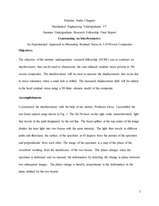
I constructed the interferometer with the help of my mentor, Professor Gross. I assembled the
two beam optical setup shown in Fig. 1. The He-Ne laser on the right emits monochromatic light
that travels in the path designated by the red line. The beam splitter at the top center of the image
divides the laser light into two beams with the same intensity. The light then travels in different
paths and illuminate the surface of the specimen at 45 degrees from the normal of the specimen
and perpendicular from each other. The image of the specimen is a map of the phase of the
wavefront resulting from the interference of the two beams. This phase changes when the
specimen is deformed and we measure the deformation by detecting the change in phase between
two subsequent images. The phase change is linearly proportional to the deformation in the
plane defined by the two beams.
2. 2
Fig.1 Electronic Speckle Pattern Interferometer
I programmed a CCD camera with a frame grabber to capture images of the illuminated
specimen shown in Fig.1 on the left. I developed a program in LABVIEW that captured 4
consecutive images of the illuminated specimen while changing the path length of one of the
optical paths by a quarter of the laser wavelength. This was accomplished by displacing a mirror
mounted on a piezoelectric translator approximately 160nm during the acquisition of each image.
The 4 images are used to construct a phase map that is linearly proportional to displacement.
I developed a code in MATLAB that plotted a phase difference map where the phase difference
is linearly proportional to deformation. 4 four images taken before deformation were used to
develop a phase map before deformation and then 4 four images taken after deformation were
used to develop a phase map after deformation. The difference between the phase maps resulted
in the phase difference map. Fig. 2 represents a phase difference image that was obtained when a
3. 3
hole was drilled in an orthogonally wrapped 3-D woven composite to relieve the residual stress
from curing. The device is available for use in the mechanics, manufacturing, and materials lab.
Fig. 2 Wrapped Phase Difference Map
A phase of –pi is encoded in the phase difference map shown in Fig.2 as black and a
phase of pi is encoded in the phase difference map as white. With a contrast of black to white
linearly proportional to –pi to pi. The discontinuity areas where the phase map transitions from
white to black sharply are areas where the phase difference was either larger than pi or less than
– pi. Unwrapping techniques allow for a continuous phase map to be encoded that will be
implemented in the future.
Challenges and Obstacles
Neither Professor Gross, nor I, were well trained in LABVIEW Virtual Instruments (VI) before
this research period began. A LABVIEW VI was necessary for controlling the piezoelectric
translator and CCD camera. I referenced multiple books on LABVIEW VI and Vision
Acquisition to develop a background on the software. I also used YouTube videos and consulted
4. 4
with faculty at UNH to learn how to use this software. James Abare, from the Technical Service
Center, was a very knowledgeable reference for electrical systems and LABVIEW VI’s.
Over the summer I improved my machining skills, particularly with the programmable milling
machine. I took the Machine Shop Training my sophomore year but I had forgotten some of the
fundamental practices of the course. I worked with the shop instructor, Scott Campbell, to
increase my confidence using the milling machine. The milling machine was used for this project
to drill accurately positioned holes on the composite specimen that was being tested.
We experienced problems where the surface of the specimen around the edge of the hole
changed so much that the phase of the beams in the before and after image were not correlated
any longer. To attempt to reduce phase map decorrelation around the location of the drilled hole,
the holes were therefore drilled using a separate high pressure drill apparatus in an attempt to
decrease the decor related region. The high pressure drill did not yield better results. The speed
of the drilling, size of the drill bit, and hardness of the drill bit are other factors that may affect
size of the decelerated region. I used tape to shield the surface of the specimen from debris
during the hole drilling process. The tape may also be interacting with the surface of the
specimen during hole drilling if the heat from the drill increases the residue left behind by the
tape. Other methods for protecting the surface including a vacuum setup, water droplet setup
among others proved to be less effective.
The storage of the images during the phase shifting period in the computer memory yielded an
unexpected problem. Although the frame grabber was designed and programmed to save images
at 30 frames per second, the allocated space on the computer memory was not sufficient to save
the images that were captured at 30 frames per second. Instead the images that were intended to
5. 5
be taken every 1/30 seconds were taken at 1/17 seconds which directly affected the acquisition
results.
Project Budget
The project budget at the time of application was adequate for the research conducted. Professor
Gross has worked with electronic speckle pattern interferometry, the system built in this
research, and mentored the budget appropriately. My advisor spent some of his internal research
funds to purchase the frame grabber and the new camera.
Significance of Research(Educational and Professional)
Residual stress in 3D woven composites degrades their reliability and can cause microcracking.
Being able to measure these residual stresses will enable engineers to evaluate the effectiveness
of process modifications on reduction of that stress. There are no currently accepted methods to
measure residual stress in 3D woven composites.
As a Mechanical Engineer, I will be designing and optimizing cutting edge products and it is
imperative to have the best design possible. Understanding materials is essential for design. As I
enter my senior year at the University of New Hampshire it is important that I improve my
communications skills and professional writing as well. From writing the project proposal, and
then a supplementary final report, my technical writing has improved towards a level consistent
with my professional engineering future. My technical toolbox has also improved drastically by
learning how to use LabVIEW Virtual Instruments, and my expanding my knowledge of coding
in MATLAB with images.
6. 6
What Has BeenLearned From This Experience
I have greatly improved my coding skills. I have learned how to create virtual instruments to
control devices using LabView. I now understand how most interferometers work. I also have a
better understanding of the fabrication of 3D woven composites and how it generates residual
stress. Learning how to systematically debug the performance of a complex experimental system
was very valuable.
The Future of This Project
The Electronic Speckle Pattern Interferometer will be used at the University of New Hampshire
by myself and Professor Gross, this school year, to characterize the residual stress in 3-D woven
composites. As I am a senior this year, my senior project involves optimizing the electronic
speckle pattern interferometer to produce clear and accurate strain measurements of the surface
of the 3-D woven composite as I relieve the cure induced residual stress by hole drilling. I will
characterize the residual stress in the composite by drilling holes in selected regions of the
composite characterized by resins and fibers while capturing subsequent images.
I will be designing and building a jig that will allow for rotation of the specimen for measuring
strain in 2 directions. With the current setup the interferometer is only sensitive to displacements
in the plane made by the 2 light beams. I test various methods to protect the material directly
adjacent to the hole that is drilled to determine the data that was previously decorrelated shown
in Fig. 2.