Draeger Electro-chemical sensor diagnositics dongle for Polytron 7000 & 8100

The document discusses new diagnostic functions in the Polytron 7000 gas detection transmitter that provide information about the condition of electrochemical sensors. The functions are enabled via an optional software dongle. The Vitality function indicates the extent to which the sensor has been used based on past sensitivity measurements. It gives a value between 0-100 to show remaining capacity but not expected lifetime. The Predictive Maintenance function uses factors like temperature, gas exposure, and vitality to assess sensor exhaustion and recommend replacement when failure is likely. Regular self-tests also check the sensor is functioning properly. These new functions allow users to proactively maintain the system and avoid downtime.

Recommended
Recommended
More Related Content
What's hot
Similar to Draeger Electro-chemical sensor diagnositics dongle for Polytron 7000 & 8100
Similar to Draeger Electro-chemical sensor diagnositics dongle for Polytron 7000 & 8100 (20)
More from Preeju Anirudhan
Recently uploaded
Recently uploaded (20)
Draeger Electro-chemical sensor diagnositics dongle for Polytron 7000 & 8100
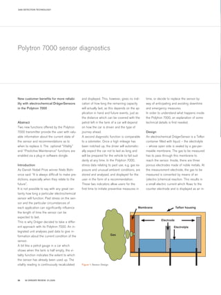
- 1. 92 DRÄGER REVIEW 01|200524 GAS DETECTION TECHNOLOGY Polytron 7000 sensor diagnostics New customer benefits for more reliabi- lity with electrochemical DrägerSensors in the Polytron 7000 Abstract Two new functions offered by the Polytron 7000 transmitter provide the user with valu- able information about the current state of the sensor and recommendations as to when to replace it. The optional “Vitality” and “Predictive Maintenance” functions are enabled via a plug-in software dongle. Introduction As Danish Nobel Prize winner Niels Bohr once said: “It is always difficult to make pre- dictions, especially when they relate to the future”. It is not possible to say with any great cer- tainty how long a particular electrochemical sensor will function. Past stress on the sen- sor and the particular circumstances of each application can significantly influence the length of time the sensor can be expected to last. This is why Dräger decided to take a differ- ent approach with its Polytron 7000. An in- tegrated unit analyses past data to give in- formation about the current condition of the sensor. A bit like a petrol gauge in a car which shows when the tank is half empty, the vi- tality function indicates the extent to which the sensor has already been used up. The vitality reading is continuously recalculated and displayed. This, however, gives no indi- cation of how long the remaining capacity will actually last, as this depends on the ap- plication in hand and future events, just as the distance which can be covered with the petrol left in the tank of a car will depend on how the car is driven and the type of journey ahead. A second diagnostic function is comparable to a odometer. Once a high mileage has been notched up, the driver will automatic- ally expect the car not to last as long and will be prepared for the vehicle to fail sud- denly at any time. In the Polytron 7000, stress data relating to past use, e.g. gas ex- posure and unusual ambient conditions, are stored and analysed, and displayed for the user in the form of a recommendation. These two indicators allow users for the first time to initiate preventive measures in time, or decide to replace the sensor by way of anticipating and avoiding downtime and emergency measures. In order to understand what happens inside the Polytron 7000, an explanation of some technical details is first needed. Design An electrochemical DrägerSensor is a Teflon container filled with liquid – the electrolyte – whose open side is sealed by a gas-per- meable membrane. The gas to be measured has to pass through this membrane to reach the sensor. Inside, there are three porous electrodes made of noble metals. At the measurement electrode, the gas to be measured is converted by means of an (electro-)chemical reaction. This results in a small electric current which flows to the counter electrode and is displayed as an in- Figure 1: Sensor Design Membrane Teflon housing Electrode Electrolyte Gas 43466_DW_Review92_S20-39 06.01.2005 15:51 Uhr Seite 24
- 2. 92 DRÄGER REVIEW 01|2005 25 dication of the concentration (Figure 1). The purpose of a third electrode (reference electrode) is to set the operating point of a sensor to a specific value, though it can also be used for diagnostic purposes. This in- volves briefly adjusting the sensor and then analysing the electric sensor signal. During this sensor self-test, the reaction must follow a certain pattern if the sensor is to be clas- sified as fully functional. Sensor properties A sensor's most important property is its sensitivity to gas, as this expresses the amount of signal which will be generated per volume of gas. A new DrägerSensor leaves the factory with a guaranteed sensi- tivity: at the end of the production process its sensitivity is measured with target gas and stored in the sensor's memory. In other words, the sensor is pre-calibrated upon delivery. Unfortunately, the sensitivity changes, i.e. decreases, over time (Figure 2). Once a sensor comes to the end of its useful life, it has only a minimum residual sensitivity. The loss of sensitivity over time depends on the application, ambient parameters and normal ageing. Extreme stress and dramatically changing ambient conditions can accelerate the ageing process. A sensor's sensitivity at a given time can be determined by calibrating it using a known concentration of test gas. The loss of sensi- tivity is compensated for by adjusting the amplification of the measurement electronics. A DrägerSensor stores the measured values from previous calibrations in its memory, this way the data is available later for soft- ware analysis. The maximum and minimum temperatures, as well as any temperature exposure, are also recorded and stored. Some sensors are exhausted when they convert measuring gas. The measurement current which is generated is used as a measure of the amount of converted gas and made available for analysis. Sensor dongle The Sensor Diagnostic Dongle memory module provides a package of innovative software to extend the diagnostic func- tionality of the Polytron 7000. A dongle can be easily retrofitted by inserting it into one of the slots. Other dongles which are available are the Sensor Self-Test Dongle and the Data Dongle. Each Polytron 7000 comes with three slots. Zeit Figure 2: Possible sensitivity curves ST-4020-2003 43466_DW_Review92_S20-39 06.01.2005 15:51 Uhr Seite 25
- 3. 92 DRÄGER REVIEW 01|200526 GAS DETECTION TECHNOLOGY POLYTRON 7000 SENSOR DIAGNOSTICS values in between are displayed in incre- ments of one, and while the sensor is in use the Polytron 7000 continuously recal- culates the sensor's vitality. In the case of a new sensor, the vitality is calculated on the basis of the factory cali- bration and its expected useful life (Figure 5 P1). When the sensor is next calibrated, its change in sensitivity is determined and compared with the previous factory cali- bration. The trend which is revealed is then used to calculate future vitality values (Figure 5 P2). If the sensitivity determined during calibra- tion deviates from the calculated vitality value, this is corrected upwards or down- wards accordingly (Figure 5 P3 and 4). The vitality value provides two important pieces of information – the change over time and the absolute value. If the value changes noticeably, calibration should be performed more frequently because the sensitivity is probably decreasing quickly, with the result that the measurement error will grow. If the vitality falls below 25, the user should start thinking about replacing the sensor (Figure 5 P5). If the adjusted vitality value is higher after calibration, this indicates that the sensor has either recovered or that a stable phase has started. A significantly lower value indicates that the sensor has either been subjected to major stress or that it is ageing quickly. A dramatic loss of vitality, however, can also be brought about by incorrect calibration. In this case, calibration should preferably be repeated. If this produces a different sensi- tivity value, the vitality will be recalculated. The vitality function permits the user to plan for the timely replacement of a used sensor. A low value indicates that the sensor is ap- proaching the end of its useful life. If vitality values decrease significantly over time, calibration should take place more often. A 10 percent loss in vitality since the last calibration can also mean that the measurement error has risen to 10 percent. As an indication of the sensitivity loss, how- ever, vitality is not the only criterion for as- sessing a sensor's performance. Over time, other properties of the sensor, e.g. its res- ponse time or cross-sensitivity to other gases, may also change. Such variables cannot always be determined by assessing the sensitivity alone, and a more detailed analysis is needed – this can be conducted with the help of the Predictive Maintenance function. Predictive Maintenance The new Predictive Maintenance (PM) func- tion uses a number of input variables to cal- culate a status indicator (Figure 6) showing the degree of sensor exhaustion. The display shows at regular intervals a schematic dia- gram of a sensor with three, two or one hori- zontal bars (Figure 7). A new sensor will ap- pear with three bars. Two bars indicate that the sensor has already reached the first stage of exhaustion due to stress and wear, but that it is still reliable. When only one bar re- mains visible, the sensor has reached its limit, and may fail at any time due to wear and tear. A number of different stress factors which can be demonstrated to influence the use- ful life of a sensor are used for the purpo- ses of analysis. These factors are measu- red, calculated and stored by the transmitter software. The life expectancy of electrode material, electrolyte and membrane is impeded by temperature. For this reason, the transmit- ter remembers how high the temperature was in the past in order to work out the de- gree of exhaustion. In addition, any violation Figure 5: Vitality curve of a sensor Vitality One of the new functions is the Sensor Vi- tality function. The current vitality value can be displayed by clicking on -->"Sensor“-- >"Vitality“ in the menu (Figure 4). The vital- ity is calculated on the basis of current and past sensitivity values and the sensor age, and indicates how exhausted the sensor al- ready is. The vitality reading is not used to correct the measured gas concentration or the displayed measurement value, and is intended solely for the information of the user. The user can check the sensor's current vitality at any time on the display of the Polytron 700 transmitter (Figure 4). When the sensor is removed, the data remain in the sensor's memory and will be displayed again correctly if the sensor is subsequently used in another transmitter. In other words, the vitality function is even available if the sensor is calibrated in a different transmitter. A new sensor has an initial vitality of be- tween 95 and 100. At the end of its useful life, a sensor's vitality reaches zero. The Figure 4: Polytron 7000 display 0 0 100 200 300 400 500 Use in days Displayedvitality 600 700 800 900 1000 1100 10 20 30 40 50 60 70 80 90 100 1 2 3 4 5 ST-3072-2004 43466_DW_Review92_S20-39 06.01.2005 15:51 Uhr Seite 26
- 4. 92 DRÄGER REVIEW 01|2005 27 of the permissible temperature limits as specified in the data sheet will negatively affect the value due to possible damage to the sensor. In some sensors, the electrode material is worn when it reacts with the measuring gas. Because the amount of material is known at the time of manufacture, the maximum gas dosage can be calculated and monitored by the transmitter. If a sensor is exposed to a lot of gas during its lifetime, this will accel- erate its exhaustion accordingly. Through- out the sensor's useful life, the transmitter measures and stores the gas dosage to which the sensor is exposed. Once the specified limit has been exceeded, a sensor may become insensitive and should there- fore be replaced. The vitality, as described above, is another input variable for the Predictive Maintenance function. If the vitality falls below a value of 25, the final stage of PM is displayed to prompt the user to replace the sensor. Dräger knows from experience how long the various sensors will last under moderate conditions. If the sensor's age exceeds a value at which the statistical probability of a sensor failure is greater than 80%, this will result in the lowest PM stage. This Methu- selah can now fail at any time. The sensor's current condition is calculated on the basis of these five variables (Figure fault. The result indicates whether the electrochemical function is maintained and the operating point is still at the optimum setting as required. This test is no substitute for a gas test to check sensitivity. If the gas access is blocked, this will not be detected in the sensor. However, this function, which runs automatically in the background, can be de- activated via the "Settings" menu and then activated manually when needed. The trans- mitter then presents the result of the test on the display. Several unsuccessful tests are evidence of a serious sensor error, in which case the sensor must be replaced immediately. Gero Sagasser, Dräger Safety AG & Co. KGaA gero.sagasser@draeger.com Conclusion The diagnostic dongle provides the user with a great deal of helpful information and funct- ions, allowing an assessment of the condition of the gas detection system. This means that the user can plan servicing and maintenance measures in time, thereby achieving a higher level of reliability and functional safety. In addition, this saves the costs which would have been incurred by taking emergency action in the event of system failures. Only DrägerSensors and the corresponding Dräger transmitters can provide this high de- gree of functionality, because they have been designed to function harmoniously together and complement each other perfectly, using the many individual data stored in the memory of the DrägerSensors. New information can be added directly to the data pool, resulting in added customer benefits. 8) and displayed. Just like a battery charge status indicator, a warning is given when it is likely that the sensor will no longer be able to perform its monitoring function reliably. The sensor should then be replaced to prevent malfunctions, false alarms and other disruptions. Sensor self-test Besides the Vitality and Predictive Mainten- ance functions, the sensor is continually subjected to tests by the transmitter to allow certain sensor errors to be detected im- mediately. Such tests are performed every 10 minutes by means of electrical stimulation lasting just a few milliseconds. This does not affect the measurement function. The sensor’s reaction is analysed and must follow a given pattern. If several successive tests are negative, the transmitter signals a Figure 6 Figure 7 Figure 8 Good OK Replace Temperature limits Work temperature Gas dosage Useful life Vitality Predictive Maintenance = Sensor exhaustion ST-3073-2004ST-3074-2004 43466_DW_Review92_S20-39 06.01.2005 15:51 Uhr Seite 27