1. Resistors
Example: Circuit symbol:
Function
Resistors restrict the flow of electric current, for example a resistor is placed in series with a
light-emitting diode (LED) to limit the current passing through the LED.
Connecting and soldering
Resistors may be connected either way round. They are not damaged by heat when soldering.
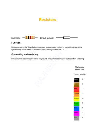
The Resistor
Colour Code
Colour Number
Black 0
Brown 1
Red 2
Orange 3
Yellow 4
Green 5
Blue 6
Violet 7
Grey 8
2. Resistor values - the resistor colour code White 9
Resistance is measured in ohms, the symbol for ohm is an omega .
1 is quite small so resistor values are often given in k and M .
1k = 1000 1M = 1000000 .
Resistor values are normally shown using coloured bands.
Each colour represents a number as shown in the table.
Most resistors have 4 bands:
• The first band gives the first digit.
• The second band gives the second digit.
• The third band indicates the number of zeros.
• The fourth band is used to shows the tolerance (precision) of the
resistor, this may be ignored for almost all circuits but further details are
given below.
This resistor has red (2), violet (7), yellow (4 zeros) and gold bands.
So its value is 270000 = 270 k .
On circuit diagrams the is usually omitted and the value is written 270K.
Find out how to make your own Resistor Colour Code Calculator
Small value resistors (less than 10 ohm)
The standard colour code cannot show values of less than 10 . To show these small values
two special colours are used for the third band:gold which means × 0.1 and silver which
means × 0.01. The first and second bands represent the digits as normal.
For example:
red, violet, gold bands represent 27 × 0.1 = 2.7
green, blue, silver bands represent 56 × 0.01 = 0.56
Tolerance of resistors (fourth band of colour code)
The tolerance of a resistor is shown by the fourth band of the colour code. Tolerance is
the precision of the resistor and it is given as a percentage. For example a 390 resistor with
3. a tolerance of ±10% will have a value within 10% of 390 , between 390 - 39 = 351 and 390 +
39 = 429 (39 is 10% of 390).
A special colour code is used for the fourth band tolerance:
silver ±10%, gold ±5%, red ±2%, brown ±1%.
If no fourth band is shown the tolerance is ±20%.
Tolerance may be ignored for almost all circuits because precise resistor
values are rarely required.
Resistor shorthand
Resistor values are often written on circuit diagrams using a code system which avoids using a
decimal point because it is easy to miss the small dot. Instead the letters R, K and M are used in
place of the decimal point. To read the code: replace the letter with a decimal point, then
multiply the value by 1000 if the letter was K, or 1000000 if the letter was M. The letter R means
multiply by 1.
For example:
560R means 560
2K7 means 2.7 k = 2700
39K means 39 k
1M0 means 1.0 M = 1000 k
Real resistor values (the E6 and E12 series)
You may have noticed that resistors are not available with every possible value, for example
22k and 47k are readily available, but 25k and 50k are not!
Why is this? Imagine that you decided to make resistors every 10 giving 10,
20, 30, 40, 50 and so on. That seems fine, but what happens when you reach
1000? It would be pointless to make 1000, 1010, 1020, 1030 and so on
because for these values 10 is a very small difference, too small to be
noticeable in most circuits. In fact it would be difficult to make resistors
sufficiently accurate.
4. To produce a sensible range of resistor values you need to increase the size
of the 'step' as the value increases. The standard resistor values are based on
this idea and they form a series which follows the same pattern for every
multiple of ten.
The E6 series (6 values for each multiple of ten, for resistors with 20%
tolerance)
10, 15, 22, 33, 47, 68, ... then it continues 100, 150, 220, 330, 470, 680, 1000
etc.
Notice how the step size increases as the value increases. For this series the
step (to the next value) is roughly half the value.
The E12 series (12 values for each multiple of ten, for resistors with 10%
tolerance)
10, 12, 15, 18, 22, 27, 33, 39, 47, 56, 68, 82, ... then it continues 100, 120,
150 etc.
Notice how this is the E6 series with an extra value in the gaps.
The E12 series is the one most frequently used for resistors. It allows you to
choose a value within 10% of the precise value you need. This is sufficiently
accurate for almost all projects and it is sensible because most resistors are
only accurate to ±10% (called their 'tolerance'). For example a resistor marked
390 could vary by ±10% × 390 = ±39 , so it could be any value between
351 and 429 .
Resistors in Series and Parallel
For information on resistors connected in series and parallel please see
the Resistance page,
Power Ratings of Resistors
7. Linear (LIN) track means that the resistance changes at a constant rate as you move
the wiper. This is the standard arrangement and you should assume this type is
required if a project does not specify the type of track. Presets always have linear
tracks.
Logarithmic (LOG) track means that the resistance changes slowly at one
end of the track and rapidly at the other end, so halfway along the track
is not half the total resistance! This arrangement is used for volume
(loudness) controls because the human ear has a logarithmic response to
loudness so fine control (slow change) is required at low volumes and coarser
control (rapid change) at high volumes. It is important to connect the ends of
the track the correct way round, if you find that turning the spindle increases
the volume rapidly followed by little further change you should swap the
connections to the ends of the track.
Rheostat
This is the simplest way of using a variable resistor. Two
terminals are used: one connected to an end of the track,
the other to the moveable wiper. Turning the spindle
changes the resistance between the two terminals from zero Rheostat Symbol
up to the maximum resistance.
Rheostats are often used to vary current, for example to control the
brightness of a lamp or the rate at which a capacitor charges.
If the rheostat is mounted on a printed circuit board you may find that all three terminals
are connected! However, one of them will be linked to the wiper terminal. This improves
the mechanical strength of the mounting but it serves no function electrically.
Presets
These are miniature versions of the standard variable
resistor. They are designed to be mounted directly onto the
circuit board and adjusted only when the circuit is built. For
example to set the frequency of an alarm tone or the Preset Symbol
sensitivity of a light-sensitive circuit. A small screwdriver or
similar tool is required to adjust presets.
9. Capacitors
Function
Capacitors store electric charge. They are used with resistors in timing circuits because it
takes time for a capacitor to fill with charge. They are used to smooth varying DC supplies by
acting as a reservoir of charge. They are also used in filter circuits because capacitors easily
pass AC (changing) signals but they block DC (constant) signals.
Capacitance
This is a measure of a capacitor's ability to store charge. A large capacitance means that more
charge can be stored. Capacitance is measured in farads, symbol F. However 1F is very large,
so prefixes are used to show the smaller values.
Three prefixes (multipliers) are used, µ (micro), n (nano) and p (pico):
• µ means 10-6 (millionth), so 1000000µF = 1F
• n means 10-9 (thousand-millionth), so 1000nF = 1µF
• p means 10-12 (million-millionth), so 1000pF = 1nF
Capacitor values can be very difficult to find because there are many types of
capacitor with different labelling systems!
There are many types of capacitor but they can be split
into two groups, polarised and unpolarised. Each group
has its own circuit symbol.
Polarised capacitors (large values, 1µF +)
10. Examples: Circuit symbol:
Electrolytic Capacitors
Electrolytic capacitors are polarised and they must be connected the correct way round, at
least one of their leads will be marked + or -. They are not damaged by heat when soldering.
There are two designs of electrolytic capacitors; axial where the leads are
attached to each end (220µF in picture) and radial where both leads are at
the same end (10µF in picture). Radial capacitors tend to be a little smaller
and they stand upright on the circuit board.
It is easy to find the value of electrolytic capacitors because they are clearly
printed with their capacitance and voltage rating. The voltage rating can be
quite low (6V for example) and it should always be checked when selecting an
electrolytic capacitor. If the project parts list does not specify a voltage,
choose a capacitor with a rating which is greater than the project's power
supply voltage. 25V is a sensible minimum for most battery circuits.
Tantalum Bead Capacitors
Tantalum bead capacitors are polarised and have low voltage ratings like electrolytic capacitors.
They are expensive but very small, so they are used where a large capacitance is needed in a
small size.
Modern tantalum bead capacitors are printed with their capacitance, voltage
and polarity in full. However older ones use a colour-code system which has
two stripes (for the two digits) and a spot of colour for the number of zeros to
give the value in µF. The standard colour code is used, but for the
spot, grey is used to mean × 0.01 and white means × 0.1 so that values of
less than 10µF can be shown. A third colour stripe near the leads shows the
voltage (yellow 6.3V, black 10V, green 16V, blue 20V, grey 25V, white 30V,
pink 35V). The positive (+) lead is to the right when the spot is
facing you: 'when the spot is in sight, the positive is to the
right'.
For example: blue, grey, black spot means 68µF
For example: blue, grey, white spot means 6.8µF
For example: blue, grey, grey spot means 0.68µF
11. Unpolarised capacitors (small values, up to 1µF)
Examples: Circuit symbol:
Small value capacitors are unpolarised and may be connected either way
round. They are not damaged by heat when soldering, except for one unusual
type (polystyrene). They have high voltage ratings of at least 50V, usually
250V or so. It can be difficult to find the values of these small capacitors
because there are many types of them and several different
labelling systems!
Many small value capacitors have their value printed but without a
multiplier, so you need to use experience to work out what the
multiplier should be!
For example 0.1 means 0.1µF = 100nF.
Sometimes the multiplier is used in place of the decimal point:
For example: 4n7 means 4.7nF.
Capacitor Number Code
A number code is often used on small capacitors where printing is difficult:
• the 1st number is the 1st digit,
• the 2nd number is the 2nd digit,
• the 3rd number is the number of zeros to give the capacitance in
pF.
• Ignore any letters - they just indicate tolerance and voltage rating.
For example: 102 means 1000pF = 1nF (not 102pF!)
For example: 472J means 4700pF = 4.7nF (J means 5%
tolerance).
Colour Code
12. Capacitor Colour Code Colour Number
A colour code was used on polyester capacitors for many years. It is now
obsolete, but of course there are many still around. The colours should be read Black 0
like the resistor code, the top three colour bands giving the value in pF. Ignore
the 4th band (tolerance) and 5th band (voltage rating). Brown 1
For example: Red 2
brown, black, orange means 10000pF = 10nF Orange 3
= 0.01µF.
Yellow 4
Note that there are no gaps between the colour
bands, so 2 identical bands actually appear as a Green 5
wide band.
Blue 6
For example:
Violet 7
wide red, yellow means 220nF = 0.22µF.
Grey 8
White 9
Polystyrene Capacitors
This type is rarely used now. Their value (in pF) is normally printed
without units. Polystyrene capacitors can be damaged by heat when
soldering (it melts the polystyrene!) so you should use a heat sink
(such as a crocodile clip). Clip the heat sink to the lead between the capacitor and the joint.
Real capacitor values (the E3 and E6 series)
You may have noticed that capacitors are not available with every possible value, for example
22µF and 47µF are readily available, but 25µF and 50µF are not!
Why is this? Imagine that you decided to make capacitors every 10µF giving
10, 20, 30, 40, 50 and so on. That seems fine, but what happens when you
reach 1000? It would be pointless to make 1000, 1010, 1020, 1030 and so on
because for these values 10 is a very small difference, too small to be
noticeable in most circuits and capacitors cannot be made with that accuracy.
15. Charge and Energy Stored
The amount of charge (symbol Q) stored by a capacitor is given by:
Q = charge in coulombs (C)
Charge, Q = C × V where: C = capacitance in farads (F)
V = voltage in volts (V)
When they store charge, capacitors are also storing energy:
Energy, E = ½QV = ½CV² where E = energy in joules (J).
Note that capacitors return their stored energy to the circuit. They do not 'use
up' electrical energy by converting it to heat as a resistor does. The energy
stored by a capacitor is much smaller than the energy stored by a battery so
they cannot be used as a practical source of energy for most purposes.
Capacitive Reactance Xc
Capacitive reactance (symbol Xc) is a measure of a capacitor's opposition to AC
(alternating current). Like resistance it is measured in ohms, , but reactance is more
complex than resistance because its value depends on the frequency (f) of the electrical
signal passing through the capacitor as well as on the capacitance, C.
1 Xc = reactance in ohms ( )
Capacitive reactance, Xc = 2 fC where: f = frequency in hertz (Hz)
C = capacitance in farads (F)
The reactance Xc is large at low frequencies and small at high frequencies.
For steady DC which is zero frequency, Xc is infinite (total opposition), hence
the rule that capacitors pass AC but block DC.
For example a 1µF capacitor has a reactance of 3.2k for a 50Hz signal, but
when the frequency is higher at 10kHz its reactance is only 16 .
Note: the symbol Xc is used to distinguish capacitative reactance from
inductive reactance XL which is a property of inductors. The distinction is
important because XL increases with frequency (the opposite of Xc) and if
16. both XL and Xc are present in a circuit the combined reactance (X) is
the difference between them. For further information please see the page
on Impedance.
Capacitors in Series and Parallel
Combined capacitance 1 1 1 1
(C) of C = C1 C2 C3 +
capacitors connected + +
...
in series:
Combined capacitance
(C) of
capacitors connected C = C1 + C2 + C3 + ...
in parallel:
Two or more capacitors are rarely
deliberately connected in series in real
circuits, but it can be useful to connect
capacitors in parallel to obtain a very
large capacitance, for example to smooth a power supply.
Note that these equations are the opposite way round for resistors in series
and parallel.
Charging a capacitor
The capacitor (C) in the circuit diagram is being charged
from a supply voltage (Vs) with the current passing
through a resistor (R). The voltage across the capacitor
(Vc) is initially zero but it increases as the capacitor
charges. The capacitor is fully charged when Vc = Vs.
The charging current (I) is determined by the voltage
across the resistor (Vs - Vc):
Charging current, I = (Vs - Vc) / R (note that Vc
is increasing)
At first Vc = 0V so the initial current, Io = Vs / R
17. Vc increases as soon as charge (Q) starts to build up (Vc = Q/C), this reduces
the voltage across the resistor and therefore reduces the charging current.
This means that the rate of charging becomes progressively slower.
time constant is in seconds (s)
time constant = R × C where: R = resistance in ohms ( )
C = capacitance in farads (F)
For example:
If R = 47k and C = 22µF, then the time constant, RC = 47k × 22µF = 1.0s.
If R = 33k and C = 1µF, then the time constant, RC = 33k × 1µF = 33ms.
A large time constant means the capacitor charges slowly. Note that the time
constant is a property of the circuit containing the capacitance and
resistance, it is not a property of a
capacitor alone.
Graphs showing the current and
voltage for a capacitor charging
time constant = RC
18. The time constant is the time taken for the
charging (or discharging) current (I) to fall
to 1/e of its initial value (Io). 'e' is the base
of natural logarithms, an important number
in mathematics (like ). e = 2.71828 (to 6
significant figures) so we can roughly say
that the time constant is the time taken for
the current to fall to 1/3 of its initial value.
After each time constant the current falls
by 1/e (about 1/3). After 5 time
constants (5RC) the current has fallen to
less than 1% of its initial value and we can
reasonably say that the capacitor is fully
charged, but in fact the capacitor takes for
ever to charge fully!
The bottom graph shows how the voltage (V)
Time Voltage Charge
increases as the capacitor charges. At first the voltage
changes rapidly because the current is large; but as 0RC 0.0V 0%
the current decreases, the charge builds up more
slowly and the voltage increases more slowly. 1RC 5.7V 63%
After 5 time constants (5RC) the capacitor is almost 2RC 7.8V 86%
fully charged with its voltage almost equal to the supply
voltage. We can reasonably say that the capacitor is 3RC 8.6V 95%
fully charged after 5RC, although really charging
continues for ever (or until the circuit is changed). 4RC 8.8V 98%
5RC 8.9V 99%
Discharging a capacitor
Graphs showing the current and
voltage for a capacitor discharging
time constant = RC
19. The top graph shows how the current (I)
decreases as the capacitor discharges.
The initial current (Io) is determined by the
initial voltage across the capacitor (Vo)
and resistance (R):
Initial current, Io = Vo / R.
Note that the current graphs are the same
shape for both charging and discharging a
capacitor. This type of graph is an
example of exponential decay.
The bottom graph shows how
Time Voltage Charge
the voltage (V) decreases as the capacitor
discharges. 0RC 9.0V 100%
At first the current is large because the 1RC 3.3V 37%
voltage is large, so charge is lost quickly
and the voltage decreases rapidly. As 2RC 1.2V 14%
charge is lost the voltage is reduced
making the current smaller so the rate of 3RC 0.4V 5%
discharging becomes progressively
slower. 4RC 0.2V 2%
After 5 time constants (5RC) the voltage across the 5RC 0.1V 1%
capacitor is almost zero and we can reasonably say
that the capacitor is fully discharged, although really
discharging continues for ever (or until the circuit is changed).
Uses of Capacitors
Capacitors are used for several purposes:
• Timing - for example with a 555 timer IC controlling
the charging and discharging.
• Smoothing - for example in a power supply.
20. • Coupling - for example between stages of an audio system and to
connect a loudspeaker.
• Filtering - for example in the tone control of an audio system.
• Tuning - for example in a radio system.
• Storing energy - for example in a camera flash circuit.
Capacitor Coupling
(CR-coupling)
Sections of electronic
circuits may be linked with
a capacitor because
capacitors pass
AC (changing) signals
but block DC (steady)
signals. This is
called capacitor
coupling or CR-coupling.
It is used between the
stages of an audio system
to pass on the audio signal
(AC) without any steady
voltage (DC) which may
be present, for example to
connect a loudspeaker. It
is also used for the 'AC'
switch setting on
an oscilloscope.
The precise behaviour
of a capacitor coupling
is determined by its
time constant (RC).
Note that the resistance (R) may be inside the next circuit section rather than
a separate resistor.
For successful capacitor coupling in an audio system the signals must pass
through with little or no distortion. This is achieved if the time constant (RC) is
larger than the time period (T) of the lowest frequency audio signals required
(typically 20Hz, T = 50ms).
21. Output when RC >> T
When the time constant is much larger than the time period of the input signal
the capacitor does not have sufficient time to significantly charge or discharge,
so the signal passes through with negligible distortion.
Output when RC = T
When the time constant is equal to the time period you can see that the
capacitor has time to partly charge and discharge before the signal changes.
As a result there is significant distortion of the signal as it passes through the
CR-coupling. Notice how the sudden changes of the input signal pass straight
through the capacitor to the output.
Output when RC << T
When the time constant is much smaller than the time period the capacitor
has time to fully charge or discharge after each sudden change in the input
signal. Effectively only the sudden changes pass through to the output and
they appear as 'spikes', alternately positive and negative. This can be useful
in a system which must detect when a signal changes suddenly, but must
ignore slow changes.