![VOL. VIII, ISSUE XXVIII, JAN 2019 MULTILOGIC IN SCIENCE ISSN 2277-7601
An International Refereed, Peer Reviewed & Indexed Quarterly Journal in Science, Agriculture & Engineering
www.ycjournal.net NAAS Rating- 5.20 Impact factor-4.035 54
F Required thrust,
CI Maximum cone index to be measured, and
A Base area of cone in case of cone penetrometer or plate area in
case of plate penetrometer= 3.225 cm2
(ASABE standard S313.2)
Assuming the maximum cone index of soil for which the system to be
designed is 2000 kPa . Hence
NFForceMaximum 65010225.3102000)( 43
Design of cylinder was done on the basis of higher force requirement
i.e., NF 650
Fig. 2 Schematic diagram of Hydraulic Circuit
The piston rod in hydraulic cylinder acts as a strut when it is
subjected to a compressive load or it exerts a trust. The piston rod
diameter is checked for buckling by using Euler’s formula. So Euler’s
strut theory is used to withstand buckling.
Euler’s equation for buckling in column
)..(
)(
2
2
ii
KL
EIπ
F
)..(
64
4
iii
d
I
)..(
644
3
22
min iv
E
LKF
d
where,
F Buckling load on cylinder rod Maximum force applied on
cylinder rod N26502
E Young’s modulus of elasticity MPa206000 ; I Moment
of inertia; d Diameter of cylinder rod
L Length of cylinder rod mm150 ; K Constant, 2 for one
end fixed and other end free
From equation )(iv
mmmd 85.500585.0
10206000
64150226504
63
22
min
Available size of cylinder rod is mm36 . Hence, the cylinder rod is
safe for buckling.
Minimum diameter of cylinder rod which can resist the load
)..(
4
v
F
d
Input parameter for equation (v) Value
Rod Material EN8
MPa380
F 650 N
fos (factor of safety) 2
mmd 36.4
380
26504
Available size of cylinder rod is mm36 . Hence, the cylinder can
resist the load.
The pressure required to develop 650 N thrust on the annular side of
the cylinder
A
F
barmmN 09.3/309.0
)3663(
4
650 2
22
Relief valve pressure should be adjusted at a pressure 25% greater
than that required to give a thrust of 650 N , considering the pressure
drop in the pipes and other components.
The piston velocity should be sec/3 cmV to penetrate into soil
to meet the standard cone penetration velocity as per ASABE S313.3.
Hence, flow pattern during extend and retract condition.
Full bore area,
222
17.31311763
4
cmmmA
and,
Annulus area,
2222
98.202098]3663[
4
)( cmmmaA
i When piston rod is extending (Fig. 3a), piston velocity, V
sec/3 cm
aA
q
A
Q
V EE
](data:image/gif;base64,R0lGODlhAQABAIAAAAAAAP///yH5BAEAAAAALAAAAAABAAEAAAIBRAA7)
Recommended
Recommended
More Related Content
What's hot
What's hot (17)
Similar to Design of tractor mounted hydraulically operated soil compaction measurement system
Similar to Design of tractor mounted hydraulically operated soil compaction measurement system (20)
Recently uploaded
Recently uploaded (20)
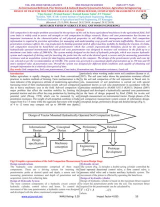
Design of tractor mounted hydraulically operated soil compaction measurement system
- 1. VOL. VIII, ISSUE XXVIII, JAN 2019 MULTILOGIC IN SCIENCE ISSN 2277-7601 An International Refereed, Peer Reviewed & Indexed Quarterly Journal in Science, Agriculture & Engineering www.ycjournal.net NAAS Rating- 5.20 Impact factor-4.035 53 DESIGN OF TRACTOR MOUNTED HYDRAULICALLY OPERATED SOIL COMPACTION MEASUREMENT SYSTEM * Vijay Kumar1 , Pramod Kumar2 , Ramesh Kumar Sahni1 , EV Thomas3 1 Scientist, 2 SRF, ICAR- Central Institute of Agricultural Engineering, Bhopal, 3 Professor, Department of Agricultural and Food Engineering, IIT Kharagpur (Received: 21.11.2018; Revised: 28.12.2018; Accepted: 29.12.2018) (RESEARCH PAPER IN AGRICULTURAL AND FOOD ENGINEERING) Abstract Soil compaction is the major problem associated in the top layer of the soil by heavy agricultural machinery in the agricultural field. Soil cone index is widely used to assess soil strength or soil compaction in tillage research. Hence soil cone penetrometer has become an important instrument in the characterization of soil physical properties in soil tillage and management studies. Soil compaction information is required in precision agriculture for managing and understanding crop growth and terrain trafficability. Moreover, soil penetration resistance affects the crop production by limiting potential yield & affect machine mobility by limiting the traction. In India, soil compaction measured by hand-held soil penetrometer which has certain ergonomically limitation, faced by the operator. A hydraulically operated instrumented mechanical soil cone penetrometer was designed to measure soil resistance in the field up to a maximum cone index value of 2000 kPa. The system mainly designed on the basis of hydraulic principle, which uses tractor hydraulic system and comprised of driving unit for inserting the probe into the soil at the desired speed, a sensor unit for measuring penetration resistance and an acquisition system for data logging automatically to the computer. The design of the penetrometer probe and cone tip was selected as per the recommendation of ASABE. The system was governed to a maximum depth of penetration up to 150 mm and 30 mm/s standard value of penetration rate. Overall the system was designed for different field conditions and capable of obtaining soil strength information in a relatively short period of time. Key words: Soil compaction, Soil cone penetrometer, Cone index, Penetration rate, Penetration resistance, Load cell. Introduction Indian agriculture is rapidly changing its track from conventional practices to modern methods of farming. Farm mechanization is the main indicator of the progressive attitude of modernizing agriculture. Increasing trend of farm mechanization results sub-soil compaction due to heavy machinery uses in the field. Sub-soil compaction is major problem that affect the machine mobility by limiting the potential traction and also affect the crop production by limiting the potential yield (Wong, 1978) which can be measured by soil penetration resistance. The weight of self-propelled combines in India ranges from 6 to 7.5 tonne while the sugarcane harvesters with weight of 9 to 12 tonne may compact soil up to 300-400 mm depths, particularly when working under moist soil condition (Kumar et al, 2015). The soil cone index shows the penetration resistance offered by the soil and compaction of the soil represents in Pascal unit. In situ, measurement of soil penetration is carried out with special equipment known as soil cone penetrometer in accordance with the procedure standardized in ASABE S313.3 (R2013). Dulawat (2007) designed and developed a hydraulically operated cone penetrometer on the basis of design proposed by Roul (2004) for in-situ soil strength measurement on instrumented tractor. Design phases of the soil compaction measurement system consist of information design, conceptual design, preliminary design and detailed design (Fig.1). Fig.1 Graphic representation of the Soil Compaction Measurement System Design Stage Design considerations The hydraulic cone penetrometer comprised of three major components. These are a driving system for inserting the penetrometer probe at desired speed and depth, a sensor unit for measuring penetration resistance and depth of penetration and an acquisition system for collecting data. Design of Hydraulic System The most common components of a hydraulic circuit consist of hydraulic cylinder, control valves and hoses. To control the movement of the cone penetrometer, a hydraulic system was designed and developed with the above mentioned components. Hydraulic circuit The system (Fig. 2) includes a double-acting cylinder controlled by hand operated directional control valve, a flow control valve, a pressure relief valve and a tractor auxiliary hydraulic system. The movement of the piston is effected by operating the hand lever. Design of hydraulic cylinder Design of hydraulic cylinder is based on the maximum thrust required to insert the penetrometer probe into the soil. The maximum thrust required for the penetrometer can be calculated by )...(iACIF where, Detailed Design Design of Tractor Mounted Hydraulically Operated Soil Compaction System Preliminary Design Conceptual Design Informational Design Design specification Machinery conception Prototype Development Engineering drawing
- 2. VOL. VIII, ISSUE XXVIII, JAN 2019 MULTILOGIC IN SCIENCE ISSN 2277-7601 An International Refereed, Peer Reviewed & Indexed Quarterly Journal in Science, Agriculture & Engineering www.ycjournal.net NAAS Rating- 5.20 Impact factor-4.035 54 F Required thrust, CI Maximum cone index to be measured, and A Base area of cone in case of cone penetrometer or plate area in case of plate penetrometer= 3.225 cm2 (ASABE standard S313.2) Assuming the maximum cone index of soil for which the system to be designed is 2000 kPa . Hence NFForceMaximum 65010225.3102000)( 43 Design of cylinder was done on the basis of higher force requirement i.e., NF 650 Fig. 2 Schematic diagram of Hydraulic Circuit The piston rod in hydraulic cylinder acts as a strut when it is subjected to a compressive load or it exerts a trust. The piston rod diameter is checked for buckling by using Euler’s formula. So Euler’s strut theory is used to withstand buckling. Euler’s equation for buckling in column )..( )( 2 2 ii KL EIπ F )..( 64 4 iii d I )..( 644 3 22 min iv E LKF d where, F Buckling load on cylinder rod Maximum force applied on cylinder rod N26502 E Young’s modulus of elasticity MPa206000 ; I Moment of inertia; d Diameter of cylinder rod L Length of cylinder rod mm150 ; K Constant, 2 for one end fixed and other end free From equation )(iv mmmd 85.500585.0 10206000 64150226504 63 22 min Available size of cylinder rod is mm36 . Hence, the cylinder rod is safe for buckling. Minimum diameter of cylinder rod which can resist the load )..( 4 v F d Input parameter for equation (v) Value Rod Material EN8 MPa380 F 650 N fos (factor of safety) 2 mmd 36.4 380 26504 Available size of cylinder rod is mm36 . Hence, the cylinder can resist the load. The pressure required to develop 650 N thrust on the annular side of the cylinder A F barmmN 09.3/309.0 )3663( 4 650 2 22 Relief valve pressure should be adjusted at a pressure 25% greater than that required to give a thrust of 650 N , considering the pressure drop in the pipes and other components. The piston velocity should be sec/3 cmV to penetrate into soil to meet the standard cone penetration velocity as per ASABE S313.3. Hence, flow pattern during extend and retract condition. Full bore area, 222 17.31311763 4 cmmmA and, Annulus area, 2222 98.202098]3663[ 4 )( cmmmaA i When piston rod is extending (Fig. 3a), piston velocity, V sec/3 cm aA q A Q V EE
- 3. VOL. VIII, ISSUE XXVIII, JAN 2019 MULTILOGIC IN SCIENCE ISSN 2277-7601 An International Refereed, Peer Reviewed & Indexed Quarterly Journal in Science, Agriculture & Engineering www.ycjournal.net NAAS Rating- 5.20 Impact factor-4.035 55 where, EQ Flow into full bore end of cylinder when extending lpmcmVA 61.5sec/51.93317.31 3 Eq Flow from annulus end of cylinder when extending lpmcmVaA 78.3sec/94.62398.20)( 3 ii When piston rod is retracting(Fig. 3b), piston velocity, v aA q A Q v RR where, = flow from full bore end of cylinder when retracting = flow into the annulus end of cylinder when retracting sec/51.93 3 cm . Hence, Retract Velocity, sec/46.4 98.20 51.93 cmv ;and, lpmmcmQR 48.7sec/00748.0sec/68.124417.31 33 (a) (b) Fig.3. Cylinder under (a) extension and (b) retraction condition respectively Control valves and accessories used in the hydraulic system The tractor hydraulic was operating at a pressure range of 150–180 bar. In order to achieve desired pressure to operate the designed system, a pressure relief/control valve of 182 to 215 bar was selected. Pressure relief valve also fitted to provide safety of the system at over load conditions. In order to bring down to desired flow of 5.61 lpm from output flow of 27 lpm, a flow control valve was attached to the circuit. The excess flow would be passed to the reservoir through the pressure relief valve. For satisfactory operation of designed system cylinder must extend, retract stroke and when not necessary remain in neutral condition. Hence, a direction control valve with four port, two way, three position, spring centered and lever operated, was selected. To connect the pump, cylinder and controlled valves hydraulic hose pipes of pressure rating of 207 bar was selected. Selection of hose pipe pressure rating was done considering the output pressure of pump and some factor of safety. Required lengths of hoses with suitable high-pressure end connections were made to connect the different components. During connections special attention was given to make it leak proof. Teflon tape was used at the ends as extra safety. Table 1: Details of the hydraulic system for soil compaction measurement system Components Dimension Pump (belongs to tractor Type: gear Hydraulic system) Capacity: 27 lpm Rated rpm: 2238 Cylinder Type: double acting Cylinder diameter: 63 mm Rod diameter: 36 mm Stroke length: 150 mm Volumetric efficiency: 95 % Maximum thrust: 650 N Working pressure: 150 bar Test pressure: 250 bar Directional control valve Type: 4-port, 3-positions, Centered: spring Control: hand operated Construction: spool type Mounting: sub-plate body mounting Maximum operating pressure: for port P, A, B-315 bar port T-150 bar 30 mm Nominal flow handling capacity: 63 lpm Flow control Valve Construction: conical throttling spool with rotation of hand knob for flow adjustment. Popet valve is for free reverse flow. Flow direction: adjustable throttled flow for A to B, free flow from B to A as indicated on valve body. Maximum operating pressure: 315 bar Pressure relief/control valve Type: direct operated variable type Operating pressure: Port P: 400 bar Port T: 315 bar Hydraulic hose Type: Flexible tube Maximum operating pressure: 315 bar Design of supporting frame According to the standard ASAE S217.11, 2000, the frame (Fig. 4 a) was designed to handle the force required for cone penetrometer during operation as well as the weight of the system. It was designed mainly with MS bar of square hollow section members and was attached to the tractor 3-point linkage. Provision was made in the frame for fixing hydraulic cylinder vertically with front end mounting
- 4. VOL. VIII, ISSUE XXVIII, JAN 2019 MULTILOGIC IN SCIENCE ISSN 2277-7601 An International Refereed, Peer Reviewed & Indexed Quarterly Journal in Science, Agriculture & Engineering www.ycjournal.net NAAS Rating- 5.20 Impact factor-4.035 56 system. The frame was fixed at a height of 635 mm above the ground taking support with tractor 3-point linkage. (a) (b) Fig. 4 (a) Frame to support different component, (b) Penetrometer probe and cone tip (dimensions are in mm). Design of penetrometer probe and cone ASABE standard S313.2 governs the design of soil cone penetrometer probe tip and shaft (Fig.4b). Two design sizes are available for use: 323 mm2 , 20.27 mm cone base diameter with a 15.88 mm diameter shaft for soft soil 130 mm2 , 12.83 mm cone base diameter with a 9.53 mm diameter shaft for hard soil The larger size is suitable for hydraulically powered soil cone penetrometer due to the stronger driving shaft. The maximum length of the shaft is governed by the maximum depth of penetration as required by any traction model, the stroke length of the selected cylinder and ground clearance. Table 2: Details of penetrometer probe and cone tip Particulars Dimension Included angle of cone 300 Base diameter of the cone 20.27 mm Base area of the cone 323 mm2 Diameter of probe 15.8 mm Length of the probe 311.4 mm Thread size in the cone 16 TPI BSW to ½ in. (internal) Thread size in one end of the probe 16 TPI BSW to ½ in. (external) Thread size in other end of the probe 16 TPI BSW to ½ in. (external) Design of Instrumentation system The instrumentation system comprised of S-type load cell for measurement of the cone penetrometer resistance. Specification of S- type load cell given in Table 3. For measurement of depth of penetration of probe, there are graduations on the driving shaft at the interval of 25.4 mm (1.0 in) and are used to identify the depth. Table 3: Details of load cell Particulars Dimensions Type S-type and compression only Model No. 12048E Capacity 200 kg Excitation voltage 10V DC Conclusions The tractor mounted hydraulically operated soil compaction system was designed for a maximum penetration resistance of 2000 kPa for very hard soil which can be suitable for any type of soil in the field as per standard ASABE S313.3. R2013. Thus, the soil compaction can be measured very fast and accurate compare to the existing system. Acknowledgement Authors are grateful to Heads, Agricultural and Food Processing Department, Indian Institute of Technology, Kharagpur for providing the crucial facilities to carry out this work. Appreciations could also be extended to laboratory mates for their help and cooperation. References ASAE S217.11. 2000. Three-Point Free-Link Attachment for Hitching. American Society of Agricultural and Biological Engineers, St. Joseph, Michigan, USA. ASABE S313.3. R2013. Soil cone penetrometer. American Society of Agricultural and Biological Engineers, St. Joseph, Michigan, USA. Dulawat MS. 2007. Design and development of a hydraulically operated cone-penetrometer. Unpublished M.tech thesis, Indian Institute of Technology Kharagpur. Kumar M., H. Dadhich and S. M. Dadhich. 2015, "Development of a tractor operated soil compaction measurement device," International Conference on Technologies for Sustainable Development (ICTSD), Mumbai, 2015, pp. 1-4. Roul AK. 2004. Tractor Instrumentation For In Situ Measurement of Soil Strength. Unpublished M.tech thesis, Indian Institute of Technology Kharagpur. Wong JY. 1978. Theory of ground vehicles. John Wiley and Sons, Inc. New York.