Water Industry Process Automation & Control Monthly - April 2024
670 873- 1-1241 hdsd&o todo-2
1. HIGHWAY SAFETY, DESIGN AND OPERATIONS
Roadside Hazards
wawe resume publicads andstreets.ed Interstate probenefit ofthe
THURSDAY, JUNE 22, 1967
HOUSE OF REPRESENTATIVES,
SPECIAL SUBCOMMITTEE ON THE
FEDERAL-AL HIGHWAY PROGRAM OF THE
COMMITTEE ON PUBLIC WORKS,
Washington , D .C .
The subcommittee met, pursuant to adjournment, at 10 :10 a.m ., in
room 2167, Rayburn Building, Hon. John A . Blatnik (chairman )
presiding.
Present :Messrs. Blatnik , Clark ,Cleveland, and Zion.
Staff present: Sameas previous days.
Mr. CLARK. The Special Subcommittee on the Federal-Aid High
way Program will please come to order.
We resumepublic hearings on the design , operation , and efficiency
of our highways, roads and streets. As we continue to review and ana
lyze someofthemost recently opened Interstate projects selected from
around the country , we are privileged to have the benefit of the com
ments and observationsof a panel of nationally recognized experts in
the field of highway engineering.
The continued assistance of these gentlemen is greatly appreciated
by the subcommittee.
Mr. CONSTANDY. Mr. Chairman, yesterday we were doing bridges
in the nine States, and we had concluded with Montana. We have
remaining with that subject,Ohio,Utah,andGeorgia.
Mr. Prisk, if you could begin, we will see if we cannot complete the
bridges and get on with signing.
Mr. PRISK . Yes, Mr. Constandy.
Mr. Chairman and gentlemen of the committee, webegin today with
Ohio,looking atbridges on Interstate 80 -S.
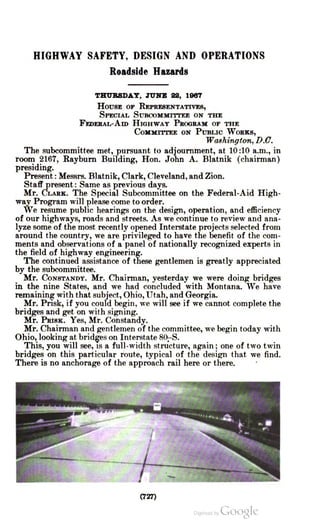
This, you will see, is a full-width structure, again ; one of two twin
bridges on this particular route, typical of the design that we find.
There is no anchorage of the approach rail here or there.
(727)
2. 728
Here is a closeup on theleft side, showing the detailthere. It shows
the open space available.
3. 729
This is another structure on the same project, which is about seven
tenths of a mile long. This is a major bridge,and one ofthe longest
in the State on the Interstate System .
From curb to curb there, you see they have provided for two lanes
and about 212 feet clearance on each side. A walk occupies the space
between the face ofthe curb and the railthatyou see.
3
AT
1
Here on the righthand istheapproach to that longbridge,andagain
the guardrail comes in with the benefit of close post spacing to stiffen
up the rail at this point. It,nevertheless,is ofa design thatwould give
enough so that a car could impale on the end ofthe structure at this
point.
ON
4. 730
Of course, there is beyond that the ever-present face of the curb,
which rises vertically from the shoulder surface.
Mr. CONSTANDY. Mr. Prisk, that is typical of what we have seen in
the preceding six States in regard to that detail ofdesign, is it not?
Mr. PRISK . Very similar.
Mr. CONSTANDY. You would say it is wrong ?
Mr. PRISK. This is not the safestdesign.
Here is a closeup ofthe same situation, showing the vertical face of
the curb ,which definitely would be a hazard continuing along the rail.
38
6. 732
Coming now to the undercrossing, you find this structure on Ohio
Interstate 80-S. The bridge piers are not shielded by railing of any
sort, butthey are offset a very considerable distance from the edge, and
on the right side there isa rail flared back butnotburied ,which carries
through the structure, giving protection against impact there.
Thatcompletes the Ohio sections.
Wenow moveto Utah,in the vicinity of SaltLakeCity,and find here
a decision point.Motoristsmust decide to go up here or here, and this
is a gorewhich is immediately ahead oftwo dualbridges, a very narrow
separation.Letmeshow you how narrow .
A
K
T
7. 733
Here it is looked at from the other end, looking back. It is probably
no more than 8 or 10 feet clearance at this end, at themost; perhaps
as little as five or six at the other end.
Mr. CONSTANDY. Mr. Wilkes, this would seem to be the ideal type of
situation for closing that space and removing the hazards that exist as
a resultofthe parapeton each bridge, and having that area traversable,
would it not?
Mr.Wilkes. I would agree with you,Mr. Constandy,that probably
itwould have been very similar in cost to build the bridge without this
opening.
Mr. CONSTANDY. Being as close as they are, it might have costeven
less to havedone it the safer way ?
Mr. WILKES. Possibly. That would , of course, have taken out this
rail and parapet entirely and made a paved section across the open
area.
Mr. CONSTANDY. Incidentally, that particular spot has the usual
skid marks of vehicles in advance ofthe structure,but the area beyond
is equally covered by skid marks from people who are yet undecided ,
after they pass the bridge, in which direction they want to go.
Beyond the structure it still is traversable for an appreciable area ,
and it is used as a crossover in that situation .
Safety would be considerably enchanced by the removal of those
inside parapets and paving the space in between .
Mr. Wilson , did you want to say something ?
Mr. Wilson . What you just mentioned could be a deficiency some
where else. It could be a deficiency in signing or in signing messages.
However, I would agree with you , every effort should be made to
make the gore area as flat and as traversable as possible.
Mr. CONSTANDY. Yes. We are deliberately omitting messages on
signs in this hearing. At some later timewe will be discussing signing
and themessages that appear on the signs.
Mr. Prisk ?
87 –757 0 – 6847
8. 734
Mr. PRISK . Here now is still another twin bridge situation, where
there is guardrail protection on the left side leading up to thatdivision
between the bridges. Still there is the same hazard, of course, that
exists.
There is not quite as obvious a solution as the previous one, to pave
over; yet it certainly is within range for consideration. Certainly it
ismuch more desirable to have these areas as open and clear as possible.
Mr. CONSTANDY. In that particular instance you can see, although
not too well, there are tracks across here, and you will see somedenting
in thatburied part of the guardrail. In fact, a car did have an accident
here.Hedrove over the guardrail and went on over into the other road
way, barely missing the bridge parapet on the end of the bridge.
This points up the possibility of a situation where you might have
someone impacting on the end of thebridge in the opposing roadway.
Mr. Huff.
Mr. HUFF. I think that points up one of the dangers of flaring the
rail too much. Had the rail been longer, and extended farther down
the road, parallel to the roadway, thatmight not have happened .
Mr. CLEVELAND. May I ask whose car that is ? To whom does it
belong ?
Mr. CONSTANDY. It belonged to Hertz, but we rented it.
Mr. CLEVELAND. I wondered if that would be a hazard, too .
Mr. CONSTANDY. In connection with that, we calculated we walked
something over a hundred miles, and it would have been much longer
had wo not taken a car.
While you raise that point, we did have a problem . I think right
there,Mr. Prisk, that is as far off the road as you can go and still get
back on the highway. That median appears to bemore sturdy than it
9. 735
actually is. It is a very loosematerial, and I had theuphappy experi
ence of getting stuck in it.
Mr. CLEVELAND. Actually, the car that would be broken down
normally would pull off to the right; is that correct?
Mr. CONSTANDY. I believe that is true. In this particular instance
there is an exit ramp on the right,and it seemed to be the least hazard
ous to put the car in a place protected by the parapets of the bridge,
so any car that might go out of controlhad the chance of missing us
because of the parapets.
Mr. PRISK. Proceeding now , looking at a bridge on Interstate 15,
which is south of Salt Lake City, we find this condition . There is a
little different treatment,because here a rail has been installed across
in front of the open drop between the dual bridges, and in this case
also,and remembering Mr. Huff's comment of a moment ago, this rail
has not been flared but is buried. I think it could be said this rail is
probably stillall too short to dothe job.
BRO
BANNER
Mr. CONSTANDY. Mr. Skeels, what would your opinion be of the
effectiveness of that guardrail, taking into consideration the length
of it, and the fact that the automobile thatmight strike it is apt to
be at a 90°angle in the faceofit ?
Mr. SKEELS. That one is rather useless as an effective guardrail. It
does define the fact there is a hazard there, but, as far as deterring a
car from going through it, practically any vehicle, at any speed what
soever, would go through that rail.
I agree further that the length of the guardrail at this end of the
bridge abutment is much, much too short. You have to have several
hundred feet in there to effectively handle a car that may be out of
control.
10. 736
Mr. CONSTANDY. AsMr. Ricker brought up the other day, there is
the undesirability of having the entire road lined with guardrail and,
considering the spacing ofthebridges on the roadway, you mighthave
that if you install just sufficient length at the bridges and the
approacFurther sugeridges.It did someext
were cut offto the videoep in
This further suggests the desirability of having paved open spaces
between the two bridges. It introduces an element of cost ; in other
words, if this median did add some extra cost because of the width
of the paving between the structures, you would want also to calculate
the saving in the guardrail to properly protect the structure, and by
the time you have done that you may find the cost of providing the
safer facility, with the paved space between the bridges, is actually
less.
Mr. Zion. Mr. Prisk, we were discussing on Tuesday the desirabilty
of flaring plusburying the endsofthis rail. Is this not another example
of where a car could easily run up on the rail and perhaps be turned
over into the highway ?
Mr. PRISK . I think that is correct, and I think this is an alternate
possibility that you need to consider with the use of this type of rail.
I think it is well to keep in mind, however, that running up here is
unlikely to have the violent effect an exposed rail would have, say, if
it were cut off at this point,and if you were to hit that squarely.
Mr. Zion. Would it not be more desirable to eliminate both possi
bilitiesby flaring andburying?
Mr. Prisk. In the previous view we had a picture of a section that
was flared down here,and this does go down to a lower level elevation.
There is a chance, unless this is quite long, that this again, with a car
on the downgrade, could top that section of rail.
Mr. CONSTANDY. These are patchwork solutions, but ideally would
it not have been preferable to pave the entire median between thetwin
structures ?
Mr. Prisk . I think every one ofmy colleagues on the panel would
agree that if this section were paved it would not be necessary to have
this as low as it presently is, which is another feature in thedynamics
of the accident.
Mr. SKEELS. I have another comment on the guardrail approaching
the parapet there. If a car does go on this at the slope they have used ,
it is unlikely the car would be tipped over. We have run many tests,
and rarely does a car tip over when it goes up a slope of this nature.
However, due to the extreme shortness of this section, the car will
keep going, and will be guided directly into the bridge parapet on the
end. It cannot get off ofit once it is on it. It will go on and hit whatever
is at the end.
It does not look as if that would be very good.
Mr. Zion . This V-shaped median, as someone suggested in the past,
there is a tendency , of course , to leave thehighway, say it is going away
from us here in the right lane, but gets into the V ; there might be a
tendency to throw it across into the approaching traffic on the other
side.
Are you suggesting the desirability of having a raised median rather
than a lower one, Mr. Skeels ?
11. 737
Mr. SKEELS. We all have seen many examples of tracks that do go
directly across the median like this. As you go down, if the car is out
of control, it tends to steer to the left, and after it starts up the other
side it tends to steer to the right; so the effective path is merely raised .
If you have a raised one, it does tend to steer back in the lane you
came from ; however, depending on the slope and the amount of rise
that you can get, it would determine whether or not it would actually
steer back into the correct lane before topping the rail.
If it topped the rise, then it would go down the other side, which
would be much worse.
Mr. CONSTANDY. Wewill have a good example on oneof the projects
that is open in Ohio. Mr. Prisk ?
Mr. PRISK. Let usmove along here.
You have seen a picture of this before. I do not think we need to
spend timeon it, but this is that bridge on Interstate 80 at Salt Lake
City where there is complete exposure of this end rail, the end of the
parapet.
THE
The possibility of a drop down here is of course nothing very
healthy, either,butthe full shoulder is carried across. Traffic normally
would be moving in this lane,but any emergency use of the shoulder
would very quickly get you into thisparapet end.
Mr. CONSTANDY. Mr. Skeels ?
Mr. SKEELS. I have just one comment on this. This bridge rail looks
pretty good, and I do not think we should condemn the bridge de
signer for notmatching the rail into it. Rather, it is failure, really, to
recognize the highway as one system , the system consisting of the
roads plus the structures, and the system has to be designed so that
the vehicle can operate effectively on allportionsof it.
12. 738
In other words, the guardrail and the bridge rail, and the shoul
derseverything — have to be considered as they work together and
connect together.
Mr. CONSTANDY. It points up the necessity of coordinating the
design by the different groups involved. Mr. Prisk ?
Mr. PRISK. Yes. Yes, very definitely.
Here again I will not spend any great time with this, because we
have seen this open section, undesirably so, between the railing and
the beginning of the structure. The opportunity is obviously here to
pave over between the two bridges that are rather close together.
Mr. CONSTANDY. This is the eighth State in which wehave seen this?
DAVIATUT
1IL
1
TI
TE
1
DTU
TI
M
Mr.PRISK. That istrue.
Mr.Wilson. May Imake a comment ? Weshould perhaps give the
Stateherecredit for utilizingthe brush curb design thatwas developed
from research performed in California, in which they undercut the
curb. The theory is that that would catch the tire underneath the curb
and help preventthevehicle from rising up and going over theparapet.
Is that not correct,Mr.Wilkes?
Mr.WILKES. I think you have expressed it very well, yes.
Mr. PRISK . May wemove along to thisbridge on Interstate 80.
13. 739
There isevidence this hasbeen struck in thisarea,with the chipping
away in the concrete at that point, very similar to the other pictureswe saw .
Here, too, is evidence that people donot always stay on the traveled
way. This is a structuremaking a connection from Interstate 15 to In
terstate 80,Salt LakeCity being in thisarea.
14. 740
These tire marks very clearly show on this side, so there is enough
shelf in this particular bridge, despite the undercut curb which is a
favorable design aspect of this structure so that the wheel marks
actually travel along here. Evidently the wheelis up high enough here,
because these were rubber tracks.
Mr. CONSTANDY. Those tracks continue along the parapet, as a
matter of fact, and there was evidence that the vehicle mounted the
brush curb and stayed up on it through that curve, and hit the end of
the guardrail at the other end ofthe bridge. It waskind of an unusual
accident,but it showsthis kind of thing can happen.
Mr. PRISK. This curb is wider than it is in desirable practice, some
what wider.
Moving along again , here is an attempt to anchor the guardrail to
the structure on Interstate 80.
JAMES
ssa
15. 741
This is a closeup picture of the same thing. One thing you notice
here is about a half-inch of rail left to take the strain at such time as
the force is applied . I am a little bit surprised this would be cut quite
so thin . That could not withstand very much of a blow .
16. 742
Wehave a picturehere,now,ofa structure where one of these washit. This is a railapproaching on theleft that I referto.
is
2
BT
1
There is acloseup ofthe damage to thecurb.Evidently a cartoppedthis curb and got up into this area,and also did a littleminordamage
to thebridge rail itself;butit was getting up fairly high. Wehavenodetailsoftheaccident.
1
All
DOVA
17. 743
Mr. CONSTANDY. Perhaps, Mr. Wilkes, that is a good illustration
of the point you brought up as an alternate to having thatmassive
parapet at the end of thebridge,by flaring down the bridge railing
asthey have donehere.
Whilethe car or vehicle hit it, it wasnotimpaled on it.Mr.WILKES. I would agree.
Mr. PRISK . It makes a glancing blow out of an otherwise severe
head-on contact.
Here is another structure entirely, where a hit occurred. This broke
away the concrete, either that or this pulled outas a resultoftempera
ture stresses on the rail.
PRO
18. 744
Mr. CONSTANDY. I think,Mr. Prisk , there was other evidence of an
accident, likewise, on that striped panel. I think on this one there had
been an accident.'
Mr. PRISK . All right. In any event, this is very similar to the pre
vious condition . The design is exactly the same. The bolt is pulled out.
Here is the way this looks on one of thebridges where the rail is not
in place. You can see the location of the bolt. Some of these are a
little bent— it is expecting a greatdealof onebolt.
Mr. CONSTANDY. Mr. Skeels?
Mr. SKEELS. I would just like to make a comment. This shows,really,
a lack ofappreciation on the designer's part of the tremendous forces
that are involved in these typical impacts. The guardrail itself, as you
recall, the sectionsare bolted together with four large bolts,two at the
top and two at the bottom , with a minor mounting bolt in the center.
The guardrail will stand a tensile force of about 100,000 pounds. To
bolt that rail to a bridge abutment with a single bolt, that looks to me
as if it might fail at 5,000 pounds, indicates a misunderstanding of
what one is trying to accomplish .
I do not think the designer really realized he was trying to fasten
the rail to the bridge in order to obtain the tensile strength that the rail
can deliver. In other words, I do not think hisgoalwas properly spelled
out to him .
Mr. CONSTANDY. The concept was good . It failed in detail.
Mr. SKEELS. Yes, I think this is right.
Mr. CONSTANDY. Mr. Wilkes, you mentioned the other day the fail
ure ofappreciation of detail in design of someofthese things. I wonder
if you care to say something about itnow ?
Mr. WILKES. I am sure the designer of that connection was not
aware of the horizontal force that would result from a vehicle struck
against therail,and did not realize it was intended thisguardrailwould
19. 745
develop a cable type resistance to the vehicle hitting the rail, so there
is a need for better understanding of how the rail is supposed to func
tion in collision.
I agree with Mr. Skeels.
09
Mr. PRISK. You turn a few amateur photographers loose, and you
do not get good pictures every time; but here is a case on another
structure where there is a bolt that actually is sticking out. That is the
end of the bolt, that little dark spot just before you cometo the face
of the parapet wall.
It is 3 or 4 inches ; you could pull the railback and forth.
Obviously this does not represent the best in practice or in
application.
Let us look at another one.
20. 746
This is a concrete parapet wall in themedian. We saw the other day
the way the guardrail treatment was applied , and you will remember
that the metal W -beam rail is flared out at this point, and at the end
of the concrete wall going this way,and also in the foreground, back
here where the camera was,is the cable-type barrier.
This simply is an illustration of the design on the structure itself.
You will see the narrow curb that projects from the wall ofthemedian
parapet.
Mr. RICKER. This is the twin bridges situation where it has been
paved between .
Mr. CONSTANDY. Yes. On this particular stretch of highway, which
is 5.7 miles, there is a series of bridges on the portions of the section
closest to the intersection with Interstate 15. Not counting the first one
we saw , they paved the space between the bridges, and, in addition,
poured a concrete median barrier.
At points farther along the highway the treatment is different, the
median is not paved , and the bridges are not, paved between , either.
Neither is there a median barrier, although the median appears to be
the same width .
Mr. Wilson. One of the objectives of highway construction I think
is to give the motorist a feeling that he is not even approaching a
structure, and this can be accomplished by giving it full shoulder
width and making all the approaching things as inconspicuous as
possible.
But I did want to point out one thing here. In the moderate-length
bridges we found it quite valuable, from the standpoint of delineation ,
to use a contrast treatment on the shoulders. You will notice here you
comeoff the travelway,and you have a white travelway there,and when
you reach the bridge you have a white shoulder.
Wehave found in the past that it hasbeen desirable to coat that with
somekind of material that is similar to the shoulder color, black lac
quer or some type of asphalt compound that will give you a contrast
treatment. This will help yourdelineation .
Mr. CONSTANDY. Thank you.Mr. Skeels ?
Mr. SKEELS. I had one comment. I assumethemedian barrier on the
bridge approach is the chain -link type ?
Mr. PRISK . Yes.
Mr. SKEELS. Really, there is no excuse for changing that, as you go
overthe bridge. All you do is create the problem where the chain -link
ends and the concrete begins. Either is fine, but there is no excuse
forchanging from one to the other.
Mr. CONSTANDY. It again suggests there is no coordination between
the bridgedesigners and the roadway designers.Mr. Prisk ?
Mr. PRISK . Looking now at an undercrossing, at the end of the
shoulder again, it is without protection at this point. The median
piers are protected.
Here you will see a median pier unprotected , and in this case the
side pier is removed so that you are way back up here before you have
any lateral obstruction at all.
Mr. CONSTANDY. So far that is very good ? That is more desirable
than a previous picture we saw ?
Mr. Prisk. Definitely .
21. 747.
Mr. CONSTANDY. Could you go back to that slide 1 minute ? Mr.Ricker?
Mr. RICKER. Iwasnotingthe pedestrian fence which Idid notthinkwould have to be that close to thepath. It is somewhat of a hazard in
itself.
Mr.CONSTANDY. This ison Interstate 15,incidentally.The picture we saw before shows a structure where a fence comes
down between the pierand the shoulder.On this structure they elim
.
HDB
DEN
SEM
AL
CEDI
2
22. 748
inated the side pier, but they created the hazard by placing the fence
along the shoulder.
Wecould not figure out why. It seemed the fence would be as ef
fective if it were continued along the right-of-way line and brought
to a juncturewith the bridge farther up that slope.
When you approach this— we were at some distance from it - we
could not figure out what that thing was ahead.When you look at that
fence end-on, it appears to be something in the road. You cannot see
the side portion of it, so you cannot see the connecting piece of fence.
You are consciousof something just off the shoulder.
So whatever advantage was obtained from the psychological effect
of driving through an open -span bridge like that was lost by the ex
istence ofthe fence.
Mr. RICKER. This again is apparently recognized by the placement
of warningmarkers along the fence.
Mr. CONSTANDY. Yes , there are several of them . Mr. Prisk .
Ver
Mr. Prisk. Moving now to ournext State,which is Georgia, we find
undercrossing structures ofthis generaltype.
The side pier is in here, clearing the edge of pavement by 14 feet.
There is no protection in terms ofany rail installed here, nor is there
on the center piers.
Here is a closeup of this same side pier, showing the detail and the
magnitude of the mass that is there, in case you happen to run off the
road atthis point.
23. 749
· This is another undercrossing, where you have a series of piers
carrying roadways overhead. This section here is paved for drainage
purposes and to retain the slopes in the fashion in which they were
built.
87–757088 48
24. 750
Also there is no protection, as you will see.
Here is an approach to a structure. I think it was remarked in a
similar view we saw yesterday, the rail height on this particular
structure appears to be quite low . This, as I recall, is only 27 inches
high, not hardly any higher than therail.
Those are the rear lights, of course, on that car proceeding away
from the camera.
Mr. CONSTANDY. This now makes all nine States having the same
design deficiency in the transition from the guardrail to the bridge
rail ?
Mr.PRISK. That is exactly correct.
Here is the closeup of one of the Georgia structures. You see
there the relative height of that concrete block at the end of the
bridge and the rail.
25. 751
This is the detail of the type rail used on top of the parapet. This
rises up vertically from the pavement edge or the shoulder.
Mr. CONSTANDY. Would you say, Mr. Wilson, it would be more
desirable to have that brush curb rather than the flat wall, as we see
it ?
Mr. WILSON . I am not sure I would be capable of answering that
question. Where we use a brush -type curb , we would certainly have a
higher concrete rail behind it, just in case it was mounted .
I think I would have to agree with whatMr. Skeels said yesterday,
this looks like the railwas too low overall.
Mr. CONSTANDY . That is something that has to be borne in mind.
If you intend to take advantage of the brush curb , you have to then
take into account the height of the parapet overall.
Mr. Wilson. I don't think I am an authority on that, really, to
comment.
26. 752
Mr. PRISK . Continuing, we find this condition at the end of the
project in Georgia,where again you have dualbridges with very little
guardrail protection atthis point. This structure,which is at the end,
this being a connection with Interstate 285, was built as a part of the
old project. We were looking from the end of the work.
We have examined away from the project. That is the condition,
perhapsthe older condition,youmightsay.
eyovoto listen
Boards ToSASA TOTTIE
ELHOR ENNow we look at somenew work in the same State.Wefind out that
bridge endsare being treated this way. You recall seeing in our review
of the guardrail practices that the State highway department is start
ing to use these blocked-out sections and Z posts; and here you see them
again,approaching thestructure.
2312
DALAR
12
URONICS
E
27. 753
This is the approach, moving from right to left on the photograph.
With this block installed in the base of the post, you will bring out
the face of the rail pretty well to this curbline, so that aspect of it is
perhaps something we can commend.
I think, still, this rail is a little lower than would be desirable. That
is a 1965 structure,as you can see.
Mr. CONSTANDY. I think that completes thematerial wehave on the
bridges.
Now I would like to ask each of the members of the panel to com
ment overall on what you have seen from the nine States, the nine
States being representative of completed Interstate sections open for
traffic in late 1966 or 1967.
I would like to have your impressions and the satisfaction or dis
satisfaction, generally,with what you have seen .
We realize there are a number of elements that were discussed that
go into the features we have been talking about,but overall we would
be curious to know whether you are somewhat dissatisfied or whether
you are pleased with what the States have done, and what should
be done in design and construction of the features wehave seen .
Mr.Wilson,will you begin ?
Mr. Wilson. I think it shows here, from what we have seen yester
day and today, that a modest cost increase in some of these features,
such as decking over structures — and in some cases it may not even
bean increase in cost - coming up with rigid structure two-span
bridges in some cases, at no increase in cost, would certainly improve
the safety features.
I think every member of the panel would agree that we have a lot
of work to do in connection with tying the guardrail to the ends of
the structures. This is something that apparently has not been solved .
Mr. CONSTANDY. None of the States did that correctly, is that true ?
Mr. Wilson. I would not be satisfied with the way I have seen
it done here.
Mr. CONSTANDY. Overall, were you satisfied or dissatisfied with
what you have seen ?
Mr. WILSON . As I have said , there are considerable deficiencies, and
with modest increase in costs you could be getting a lot more safety out
ofit.
Mr. CONSTANDY. Thank you,Mr. Wilson.Mr. Skeels ?
Mr. SKEELS. I certainly agree that all of the projects examined
showed the same general types of deficiencies, and there are quite a
number of them . We saw a number of attempts to improve the situa
tion. There are lots of ideas on railing design. Weeven saw a few on
the attachmentofthe guardrail to the bridge parapet.
These designs obviously were made by people well intended , who
intended to do a good job .Most of them we criticize asnot being a good
job , or notbeing as good as we think the state of the art would allow .
I would certainly like to encourage the use of real full-scale tests to
evaluate designers' ideas. I am a testingman, and I may be overempha
sizing this angle. I realizemany of the designers do not have facilities
to conduct full-scale tests on their designs. If they do not, they should
make use of designs that have been tested or evaluated and proven that
they perform properly.
28. 754
thet'thatthesearch donetheg
In this case,as in many others, intuitive design is not always proper.
The design has to withstand a dynamic situation of a car impacting it
at a considerable angle I use the word “ car" ; I should use the word
" vehicle” — and the designs do not always respond as the designer
thought they would.
Hence, theonly way to really appraise this is to run tests on them and
evaluate designs. This approach should be encouraged, instead of al
lowing a designer to put in anything he thinks happens to look good .
Mr. CONSTANDY. Thank you. I think there is a great deal ofmerit
to what you suggest in the testing of designsbefore incorporating into
the projects. I think there might also be something to be said for the
fact that there is already some knowledge which has been derived as a
result of research done by several people in California, Texas, and
yourself, to confine it to the group here.
Butwe repeatedly see there is a failure of appreciation of the signi
ficance of what has been learned from the research that has been done
already. You do not see it being applied, even those things alreadyknown.
Mr.Zion . Mr. Skeels, we have no standards or criteria established
by which these designs could be compared ? No standards or criteria
have been established ?
Mr. SKELLS. I do not know exactly what you mean, I guess. We
have evaluated them
Mr.ZION . I thought your concept of testing was certainly a valu
able one,but would it not be preferable to establish some sort of stan
dard by which these things could be compared initially ?
In other words, rather than having each State participate in itsown
design testing and establishing criteria,would it notbewise if we could
make some federally recommended criteria for design ?
Mr. SKEELS. It would be good to have a performance standard
available, which they should meet. There obviously are many designs
that would beadequate, but they all have the same function to perform .
If a performance standard could be developed , this would be good. As
far as I know , there is no performance standard for many of these
items.
Mr.CONSTANDY. Is it nottrue they are in the process ofbeing deve
loped ? Is this work not being doneby the new agency in the promulga
tion of standards ?
Mr. Prisk, is this not one ofthe things that willbe doneby the new
safety agency ?
Mr. Prisk . This is the responsibility assigned by the legislation
passed by the Congress last year, to develop performance standards
for safety in highway design ; yes, sir.
Mr.CONSTANDY. They willbegin to comeout the firstof July ; is that
not true ?
Mr. PRISK . Initial standards will, yes.
Mr. CONSTANDY. Mr. Huff .
Mr.Huff.Myback vision is always 20/20. Ido not have quite that
good vision looking ahead.
I have listened with great interest to the discussions and views of
the pictures ofbridges during the last half day. As I have noted down
here, they consist of bad connections of rails to bridge ends, massive
29. 755
end piers, too close undercrossing piers, poor delineation , low bridge
railing and high bridge railing, and unpaved , narrow medians.
I believe that we could all agree that some standards should be de
veloped that would cure the evils caused by those things that we have
seen .
I also believethatmost of the things wehave seen willmeet our pres
ent AASHO standards, which , of course, were not written in enough
detail to cover all ofthe thingsthatwehave seen .
It is my opinion — and I agree with one of the gentlemen to my
right, who said that we should have a design system thatwill include
the entire road, including the bridges— it should be a system that
connects the rail from the bridge to the road, a system that carries
themedian continuously across the bridge,wherever practical or pos
sible,you might say.
Such design standards, in myopinion , should be formulated through
AASHO being composed of themember States.
It is my opinion from contacts I have had with design engineers
from a great many of the States, they subscribe to the standards set
forth in the new yellow book , and are willing to turn to them for the
solution of many of the problemswe have seen here on bridges and
other things.
I would likealso to commenton someofthe things that perhapswere
not expressed in the discussions here today and yesterday. One is the
width of the bridge.
It has been noted we should run the shoulders entirely across the
bridge. There is nomention made as to how wide the shoulders should
be .
If there is an acceptance of the 10 -foot shoulder on the right and
the 6 - foot shoulder on the left, on our highways that are carrying
vehicles where 85 percent are driven at 70 to 75 miles an hour, it is
my opinion those shoulders are not proving to be wide enough, par
ticularly the one on the left-hand side of the road, which is, as all
laymen know , carrying the fastest stream of traffic. We are making
those 6 feet wide,whereas those on the rightwemake 10 feet wide.
Of course the shoulder has two purposes. One is to clear fast traffic,
particularly the traffic that gets outof control. The other is for refuge
for broken -down cars ; that is the reason for putting it on the right.
I believe protection to fast traffic is becoming just as important, and
perhaps even more important, than the traffic clearance on the right
hand side. How wide these ought to be, I must admit, I do not know .
The widths that were selected , I believe, were selected on the basis
of the subjective ideas of the people in AASHO who developed the
Interstate standards back in 1956, and I must say that I was on the
working levelofthe group that selected those.
They appeared to be wide enough then , but with faster automobiles
and more powerful automobiles, I think such things as shoulder width
and all of these other things should be taken up immediately , and the
minimum standards raised to take care of the conditions wehave now ,
which may not even be comparable to what they will increase to in the
next 15 to 20 years.
I also noted in the successive stages of the projects that have been
built, they are making improvements, perhaps not fast enough, but
30. 756
the rank and file of these States that were shown are making
improvements.
Mr. CONSTANDY. Yes. I think that is something we should bear in
mind, Mr. Huff, being very careful to recognize this in looking at
old work .
When we went to the newer projects you could see there had been
some upgrading in standards.
I think we might reflect on how long it has taken ,and the fact that
the improvement frequently still overlooked something that should
have been obvious to someone who had a complete understanding of
the problem before they made the change.Mr. Huff ?
Mr. HUFF. I have onemore comment I would like to make. I missed
it.
I certainly agree with tests and research .Observation of roads under
operation is very important in this matter. I think that each State
should spend somewhat more than it is now spending on testing and
research , which consists of, I might say, plant research or observation
of installationson the highways themselves.
Mr. CONSTANDY. Thank you . Mr. Wilkes ?
Mr. WILKES. My comments are as follows, Mr Constandy. I think
I could say without any reservation that all of those bridges shown
in the photographs, although they appear to be deficient in certain
respects, were designed in accordance with existing AASHO bridge
specifications, and that the designer was principally concerned with
the structural adequacy of the elements that he has included in his
design.
Mr. CONSTANDY. In the design of a bridge that stands up ?
Mr.Wilkes. Correct.
Mr.CONSTANDY. I think that should be recognized . Actually thearea
that we are concerned with here is whether you have a bridge that
will satisfy the needs of traffic, and whether wehave done asmuch as
is possible to bedone to provide the greatest degree of safety to the per
sons using it.
Mr. WILKES. That is correct, and if there are deficiencies, we should
recognize them as early as possible, and revise our bridge specifications.
The second is,many bridge engineers, being men of strong convic
tions, do not agree that safety walks are dangerous. On the contrary,
they believe that the restricted -width bridges should have safety
walks.
However, in the light of the strong recommendation made by the
AASHO Special Safety Committee, the majority of all States have
revised bridge specifications now under construction to the extent
possible to eliminate the safety curbs. Almost without exception the
States haveagreed to eliminate the widecurbs from the future designs.
Mr. CONSTANDY. If I understood the first part of what you said ,
relative to the safety walk, the bridge engineers have strong convic
tions they are desirable, but the new requirement in the yellow book
will demand elimination in most areas ?
Mr. WILKES. That is correct. They feel this finding of the safety
committee is still an opinion ; that they have not seen the evidence
that it does constitute a hazard, and neither can they supply evidence
that they are, in reality, safety walks. They are bowing to the will of
31. 757
To a very ownminsposed endturbi
the majority , as I say, almost without exception, and are eliminating
the safety walks from future designs.
There is a third fact that disturbs me quite a bit. We saw in the
picture unprotected exposed ends of the curbs and I really could not
justify in my ownmind leaving this curb exposed .
To a vehicle, that certainly results in a disabling accident if it
should run onto this curb. The car would have no chance to recover
at all ; and this could be improved at very small expense, to provide
an adequate transition, or a much better transition . Apparently we
are stillmaking the samemistakes.
The last remark is that apparently there was inadequate coordina
tion between the bridge designers and the roadway designers to
produce the safest highway that can be produced from our present
knowledge.
Mr. CONSTANDY. Do you know, Mr. Wilkes, for how long the
AASHO standard for the bridge railing was in effect,up until it was
changed recently ?
Mr.WILKES. No.
Mr. CONSTANDY. It was for someyears,was it not?
Mr. WILKES. Yes. I would say there was no change in the railing
specification for a period of more than 15 years, until 1961 when
the heavier loading was reviewed and approved by the committee.
Mr. CONSTANDY. Up until 1964, would a bridge railing built pursu
ant to the AASHO standard contain a vehicle on a bridge ?
Mr.WILKES. I would say in a majority ofcases they did .
Mr. CONSTANDY. Ifit is built only to standard ?
Mr. WILKES. Built to design ; yes.Most of the rails that performed
badly would not even meet the then -existing design standards.
Mr. ConstaNDY. Of AASHO ?
Mr. WILKES. Of AASHO .
Mr. CONSTANDY. If the bridge railing were built to the pre-1964
AASHO standard, it would contain an automobile if struck ?
Mr. WILKES. Let me say in most cases the rail performed in an
acceptable manner.
Now , certainly there are many instances where the vehicle did go
through the railing, so I will not claim 100 percent performance, but
most of the timeit did .
Mr. CONSTANDY. You know , of course, we have no professional
competence on this staff in the engineering field ; we do not purport to
have.
However, I have had many conversations with bridge engineers
dozens of them — relative to design strength of the AASHO standard
bridge railing prior to 1964.
It was my impression , as a result of these conversations, that if
they had answered the question, the answer would be no, it would
not contain an automobile .
Mr.Wilkes. Letme say that,as a result of this Highway Research
Board Special Report 81, certain angles of attack and speed of the
vehicle wereprescribed for a bridge rail orparapet test.
I would agree that the pre-1964 bridge specifications for rail design,
according to those specifications, would not contain a vehicle at the
speed and direction recommended for testing in this bulletin .
32. 758
Mr. CONSTANDY. That is apt to be a large percentage of the vehicles
striking the bridge rail?
Mr. WILKES. No; I do not think all vehicles hit a bridge rail at a
20°angle at 60 milesan hour.
Mr. CONSTANDY. No, I would not suggest that, either.
We will get into this in somewhatmore detail later in the hearing,
because I think it is significant. Many States built bridge railings in
excessofstandards setas a minimum by theAASHO policy .
Mr.WILKES . I would agree.
Mr. CONSTANDY. We have to recognize there that the State has
the latitude to exceed theminimumsas set by the AASHO standards,
does it not?
Mr. WILKES. Yes ; it does.
Mr. CONSTANDY. In many cases Stateshave done so ?
Mr.WILKES. Yes ; they have.
Mr. CONSTANDY. So, if we reflect on the projects which we have seen
here in the nine States, the fact may be that they have been built, in
the elements which have been analyzed, to the AASHO standards and
still not be adequate, but the State is not precluded from going above
those standards in providing a facility which would be adequate from
a safety standpoint?
Mr. WILKES. That is correct.
Mr. CONSTANDY. Mr. Ricker.
Mr. RICKER. Several different organizations, particularly in the
State of New York , have made extensive crash tests of bridge rails.
Movies of these tests have been shown in severalmeetings, such as the
Highway Research Board . To those of us who have seen the movies,
there is only one conclusion : That we never want to hit a bridge rail.
There are just spectacular crashes, including such things as the
motor flying out of the vehicle and over into the far side of the rail.
I think we might consider a little bit that the nature of limited
access highways is enough that it greatly increases thenumber of struc
tures on a particular section of road. If you have a land -access high
way, about the only time there is a bridge is when you are crossing a
river, but a limited -access highway hasmany,many more structures,
and this is perhaps why they are becoming increasingly important in
accident involvement,and increasingly important thatthey be designed
safely .
On thematter of connecting the guardrails into the parapets, I have
been personally advocating a better design of this for some 10 years,
based on direct observation ofaccidents and so on. I am all in favor of
it,and I think they must be connected ,and well connected .
One other observation . Wemay wonder why people run into bridge
piers. I am speaking of the piers supporting the overhead structure,
which may be only two feet wide. This looks like a small spot to hit.
Certainly when it is drawn out on a plan ,or from an aerial view , you
wonder why anybody goes out of his way to run into them .
Actually, in appearance to a vehicle , they are 14 feet wide, if you
have only 2 feet of concrete ; because if the vehicle touches them any
where, it is a head -on crash .
Likewise, you can compute they are about 400 feet long. If a vehicle
wanders over the median anywhere within 400 feet, it is almost certain
33. 759
to hit the bridge pier. This is why they are suddenly so much more
importantthan they used to be.
Mr. CONSTANDY. That is a very good observation.
A chart illustrating the foregoing points is inserted in the record at
this point:)
POTENTIAL HAZARDS OF TYPICAL ROADSIDE PIERS
~ PROJECTED VERSUS ACTUAL DIMENSIONS
A. VEHICLE DRIFTS OFF PAVEMENT
PROJECTED WIDTH
AS-MUCH-AS 14 FT.
PAVEMENT- - - -
SHOULDER POSSIBLE VEHICLE PATHS
PROJECTED LENGTH
AS-MUCH-AS 190 FT.
ACTUAL
WIDTH
2 % FT.
B . VEHICLE LEAVES PAVEMENT ABRUPTLY
PROJECTED WIDTH
AS MUCH AS 22 FT.
- -- - PAVEMENT
ACTUAL
WIDTH
21% FT.PROJECTED LENGTH
AS-MUCH AS 50 FT.
: What was your overall impression of the work you have seen on the
nine projects welooked at,Mr.Ricker ?
Mr. RICKER. I am afraid wehave never really faced up to this mat
ter of connections at the end ofthebridge.Some people have advocated
safety walks, somesay eliminate the safety walks. Somesay connect
the guardrail in directly to the parapet,and so on.
There is no existing standard. I do not think that we can fault indi
vidual designers for not complying with the standards that exist. I
think wedo recognize thereis a need for a connection,andwe had better
hurry up and get a good one.
Mr.CONSTANDY. Thank you.Mr. Prisk , I think wecan now turn our
attention to lighting. Wehave had, out of the nine States, only four
which have lighting. The other five do not. The four which do have
are Rhode Island, Georgia, Montana, and Oklahoma.
Perhaps,Mr. Prisk , you mightbegin our discussion on lighting.
Mr. PRISK. As you mentioned,Mr. Constandy, not all of the nine
projects did have lighting installations. I think thematter of the light
ing of a controlled access facility is perhaps still an unsettled matter,
because there are bodies of information that suggest the importance
of lighting in somesituations,and in other cases indicate thaton these
newer highways where there are fewer obstructions, fewer opportuni
ties to depart from a prescribed alinement, fewer opportunities tomeet
anyone at an intersection than under thenormalcity street conditions,
that lighting is probably not as necessary and that headlights will do
the job adequately. However, in those cases where lighting has been
a feature of the projects we have been looking at, we have examined
34. 760
that aspect of design since it does relate to the general subject area of
design efficiency and operation of the Interstate System .
Take a look at someof these observationsnow .
Here in Rhode Island, you first see a multilane facility installation
of a fully lighted section where the luminaires are set 2 feet beyond
the edge of the 10 - foot shoulder making them 12 feet from this white
line that you see here. This is common throughout the length of this
project. They appear both on the left and on the right as you will see .
FE S
SIVAS 20 HOD
These poles are constructed so at their base they appear this way.
GE
35. 761
This is an aluminum pole and this is cast aluminum around the base
here. This is concrete,built- desirably so — flush with the surrounding
level of the ground.
So that is the Rhode Island installation weare looking at now.
These poles are rather frequently knocked down because of their
nearness to the pavement. And this is one knocked down that we saw .
This is the base at this point, outhere ( indicating), just 2 feet off the
roadway. This is the position of the pole as it came to rest.
36. 762
You can see the remainsofthebase. This isso constructed and wired
that the pole breaksaway at the base.Here are remnants ofthese little
clip sectionsthat go on thebottom . And thewiring is such thatthere is
an automatic disconnect when the pole is knocked down.
al
V
Here isa closeup of thepole after itwashit,presumably an impact
aboutbumperheight,as you can see.Andthepoleisbroken awayhereat the base.
37. 763
Still another picture of that same pole.
DaISSN
AUT
VO
ON
Here isanother location. In fact,duringthe evening thatwe stayedover there in Providence, this pole wentdown.Wesaw it working the
nightbefore and down in themorning when we first cameout. So this
is a very fresh situation, the car thatwentacross the roadway here
you can see the skid marksafterhehit the pole.
13
IA
RO
SEN
33*
ok
38. 764
Pursuing this a little bit further with the authorities in Providence
since that time, we were unable to find any accident report was filed
for this pole knocked down at all. In other words, the driver ap
parently survived this breakaway-type pole accidentwith only damage
to his vehicle and went on his way.
Here again is a closeup of that particular installation, the onemost
recently broken.
Mr. CONSTANDY. That picture shows something else, does it not,Mr.
Prisk, the manner in which it is provided that the high-voltage lines
willnot cause an additionalhazard by being broken . Could you explain
that?
Mr. PRISK . Yes, I had mentioned that on the earlier slide,Mr. Con
standy, that there was an automatic disconnect. These ends here and
here pull away from the wiring inside the pole so that when it goes
down, thereisan automatic disconnectof the power,no opportunity for
fires to develop or any short circuits in the line or even interruption of
service to the other lighting units.
Mr.CONSTANDY. Mr. Ricker.
Mr.RICKER. Youmight note that that concrete base is about 2 inches
out of the ground. That should be about the maximum , particularly
when you consider erosion thatmay take place later on . Not having
seen the pictures, I do notknow whether you have someothers that are
higher. But I suspect that 2 inches is about the most that should be
allowed to protrude.
Mr. CONSTANDY. Thank you.
Mr. PRISK. Very good observation .Glad to have it,of course.
Most of these I would say are limited to within 2 inches.
39. 765
This is that pole knocked down showing the extent of damage there.
Bending the lower part ofthis aluminum pole.
Of course,the luminaire itself, the glassware, is broken as it comes
down.
Here is another one— this is off the project but still on Interstate
95- indicating a poleknocked down. It is rather interesting to us that
in the very short distance thatweare looking at here, we saw four or
five light poles actually laying along the roadside as this oneappears.
abile
87-76706849
40. 766
There is information available in other areas of the country that
supports thedesirability of having polesmorethan 2 feet off the edgeof
thepaved surface.
In Chicago, on their expressway systems, there have been studies,
paragonsmade ofthe rate ofknocked down light poles on thebasisofmiles of travel,andwefind thatmoving the poles from 4 to 8 feet away
from the edge of the pavement will cut the light pole knockdownsby
abouttwo-thirds.
I
I
i
.
Here isan installation ofthe sametypeof pole behind the guardrail,
the rail of course being put in here for this embankment.
Now ,down here,let'stake a closer look (slide) and at this same loca
tion you will find wood poles thatare put up, and they are inside the
rail.
Mr. CONSTANDY. They are notbreakaway,are they ?
Mr. PRISK . These are wood poles that are not intended to break
away ; no, sir. I might say this is on a spur to Interstate 95 ; it im
mediately adjoins the project, feeding the project,as a matter of fact.
Mr. CONSTANDY. This is apparently a temporary installation until
that spur is extended ; the lights are mounted on the wooden pole.
Would you call them telephone poles ?
Mr. PRISK. Yes. Utility poles.
Mr. CONSTANDY. Inside the guardrail.Here again wehave somebody
doing something wrong. While the State is to be commended for their
efforts elsewhere, where they install breakaway light poles, whoever
installed these wasn't thinking the sameway as theman was whomade
the decision to use the safe breakaway light poles. This is an unneces
sary hazard .
Ár. RICKER. Is it possible the wooden poles were installed by a
jurisdiction other than lighting ?
Mr. Prisk . It is altogether possible. It could have been a local
jurisdiction.
41. 767
Mr. CONSTANDY. Conflicting jurisdictions is another subjectwewill
get into later in these hearings. It is one that comes up.
Ofcourse the motorist striking it is concerned only with his well
being, but that does present a problem and we will explore it further
asthe hearingsdevelop.
Mr. PRISK. Here are someother pictures, in the same State again.
.
In this instance the pole ismounted in themedian barrier showing
how nicely this can be fitted in with concrete base essentially flush
with the paved median barrier,and protected here by the guardrail.
SOUTH
13
KO
I.RA
42. 768
Here is one over here, you see is exposed. The normal roadside
condition is an exposed pole.
Mr. SKEELS. This is in a gore .
Mr. WILSON. I would like to comment on that last pole Mr. Prisk
pointed out. It is on the outside of a curve.We found that this is not
a good place to put a light standard or really anything else that
might be hit. These could be just as well placed on the inside of
places likethis.
Mr. PRISK . Thank you.
Aswemove along, we find an obstacle, on the roadside,of thismag
nitude. I show you thispicture first.
And then I show you this view ofthe samething to give you an idea
of where it is and its relevant size. This is the control system for the
lighting that we are just looking at, and just dropped in here on a
section of the tangent portion of 1-95, all too close to the roadway.
There is a slope, where this picture was taken , which rises up here
and is clear perhaps within the right-of-way for possibly another 40
feet from that location. It could have been moved up the bank .
The only consideration Ican understand for this location is that it is
a little easier to get here and read the meter or service the equipment
inside of the box.
Mr. CONSTANDY. It is unfortunate. Those two things were the only
features which spoil an otherwise very good installation of lighting,
the existence of that control box and the unfortunate existence of the
two lightpoles inside the guardrail.
Mr. PRISK . That is true.
CHOUSE- NUS
43. 769
Experience with the control box system which they have has been
relatively good.
Now we are in Georgia , back to the section that is near Atlanta,
where light poles are installed at this distance (indicating ] which
will measure just about a foot to the edge of the transformer base.
This is not an aluminum or otherwise frangible base. This is a steel
pole all theway.
44. 770
Here are someof the things that Mr. Wilson mentioned, the same
narrow clearance to theedge of pavement, and 1 or 142 feet, possibly
2 feet at the very most, showing off the edge of that pavement the
unprotected posts or base.
Here is one upon the parapet wall of the bridge which does
afford the protection by the structure that is there.
45. 771
Here isonecloseupshowing installation behind the guardrail.
Mr. CONSTANDY. That is just by chance, is it not,Mr. Prisk ? The
guardrail is close to the bridge.
Mr. PRISK. The guardrail is not put in there in any sense to protect
the pole. Aswe saw , the other random poles came outside the guard
rail. This rail is in here on account of the embankment and the
drainage system here.
Here now is the approach to the Dobbins Air Force Base north
of Atlanta , and you will see the pole installation here, too. The
guardrail beyond it is in to protect this sign and leading up toward
the undercrossing structure. The light pole is exposed.
La
46. 772
Mr. RICKER. Excuse me.
Mr. PRISK . Yes.
Mr. CONSTANDY. Mr. Ricker ?
Mr. RICKER. This picture illustrates another problem , although it
is only a picture that could be taken from a different angle. Oftentimes
the light poles block out the proper view of the sign and they must
be placed in relationship to each other or else one pole after another
will block a sign so you cannot read it at all.
That would be another reason formoving the light pole back so as to
geta clear view ofthat sign.
Mr. CONSTANDY. Thank you.
Mr. PRISK . Very good point.
This is a typical installation. You will find at the entrance ramps
on the project where there is the one pole put up here very close
to the junction of the entrance ramp and the through roadway, and
two poles put beyond that along the acceleration lane. This pole, of
course, ends up being on the outside of the curve.
There are two here.
Mr. HUFF. Mr. Prisk , you mentioned horizontal dimensions on the
light standard. What generally are the vertical dimensions, height
above the road, and so forth ?
Mr. PRISK . These, I believe- - I looked at the planson these I would
only have to recall that these are about 35 feet above the roadway.
Fairly high.
This is what you find in the urban section,entrance ramp coming in
here and in this case a double luminaire mounting. This is in contrast
to the previous picture where it is a single light over the roadway.
1
47. .
Here, as a truck stops, you can see something of the horizontal
dimensions thatwe are talking about; the clearances from the side of
the truck to these poles is so little that you might think that picture
was staged.But thatman just stopped there and we happened to geta picture of him .
48. 774
This is brand new work off the project. This is identified with
the south expressway running out to theairport. Camein past this and
picked up these pictures at that time. So today, even though this is
still under construction, this is what wehave for light pole placement
on that project, which is part of the Interstate System , also.
ARTIS
229
49. 775
Here is another part of the same new work showing, rather inter
estingly, a deliberate placement of rail rather well back from the nose
or gore decision point, which is about where the camera is, but inter
estingly enough leaving the light pole in here in an exposed position
in relation to this rail that is going to bebuilt around through here.
Mr. Zion. That is apparently not a breakaway type of pole either.
Mr. PRISK . No.
Mr. Zion. Is that a concrete foundation it is sitting on ?
Mr. PRISK. Yes, sir, it is a concrete foundation .
Mr. Zion . Does this not cost more than the aluminum breakaway
type poles you were showing previously ?
Mr. PRISK . They are competitive in most cases.
Mr. Zion . Again would this not indicate a need for establishing
someFederal criteria for light poles aswellas for placementof guard
rails, and tying them to bridges in highway construction ?
Mr. PRISK . I think that it would deserve commensurate considera
tion along with these other itemsthat you mention as far as the per
formance standards are concerned , yes.
I do not think that you need to limit materials to aluminum or steel.
You can accomplish performance with either material. I do not con
demn one or the other.
Mr. Zion. Certainly we are not fighting the concrete people, but
certainly this is one of the danger elements that could be reduced in
erecting light poles ; do you not agree ?
Mr. PRISK . If you are talking about that base, I fully agree, yes.
Mr. CONSTANDY. Congressman, you raise an interesting point, if you
will allow a commentabout the need for Federal standardsto regulate
some of this.
50. 776
Wewill look at light poles and some of the other elements. You can
have discussion and differences of opinion on whether it is feasible
to remove the shoulder piers on bridges, whether it is feasible to carry
shoulders across bridgesthat are a given length. You can get into some
meaty arguments, I am sure, with people who may even have some
proof for their point of view .
This, however, is a relatively simple thing. A light pole can either
be put up to be frangible and save themotorist, or it can be put up in
a very rigid fashion and the result would be likely to kill themotorist.
We have had testimony about light standards on the Capital belt
way, on the Maryland section, which repeatedly, not infrequently,
cause severe injury or death .
It is a simple election : You can either put one up thatwill withstand
the impact of the automobile, or you can put one up which will give
the motorist who strikes it half a chance to survive. There is no great
argument here.
There is available a wide variety of types of light bases and poles.
You can have an aluminum pole with an aluminum frangible base
that is either mounted on a transformer base or the type you have seen
here in Rhode Island. You can have a steel pole, steel base ; it can be
breakaway . You can have a slip -base pole there is a wide variety
to choose from . The prices are relatively competitive. It comes down
to a simple thing : When you install the light pole you intend to give
the driver of the automobile a chance to survive or you do not.
Highway departments should be able to decide this withoutAASHO
standardsbeing set,or threatofpenalties for notabiding by standards
set by the Federal Government. Here is an area, it just strikes me,
that could be improved by highway departments without regulation ,
so that a light pole, if struck, will yield . I think it is distinctive in
that respect.Mr. Huff ?
Mr. HUFF. I would like to say that technology of highway lighting
has advanced probably more rapidly than anything in our safety field .
Up until not many years ago, the general practice was to use illumi
nation poles about 30 feet in height. One problem attendant to the
low elevation was that you had to put the poles up near the edge of
the road in order to light the highway. That is in particular where
you had to lightthree or four lanes.
Now , that created the collision problems, which I believe have been
found in all the States, of people running into light poles. That has
proved in the past to be one of the most hazardous things we have had.
So to cure that, the highway engineers, in conjunction, of course,
with the electrical people, have developed new lighting standards up
to 45 and 50 feet high, No. 1, that will enable you to move farther
away from the road. It will also enable you to use fewer poles than
you had to in the beginning, and it will enable you to have fewer
knockdowns, of course.
Incidentally , when you knock one of those down, it does cost money
to put it back up and you want to have as few knockdowns as you can
and as few replacements as you can .
The only problem that has comeup is thatmany, many of the light
ing projects are maintained by local jurisdictions. Sometimes it is
difficult to get a local jurisdiction to purchase equipment or mainte
YoNow thatthestateoneofthe
51. 777
nance equipment tall enough that will go up and reach these 50-foot
height lamps. And that is one of the problems that most of us have
been working on ; we have been using frangible bases here for, oh ,
nearly ten years. We are well satisfied with them . So far as I know
wehavenothad a fatalaccident running into a frangible base, whereas
wehave had many fatal accidents on the old rigid -type base of which
wearemoving to replace allthat wehave.
Mr. Zion. Would this not suggest that we make these regulations
sufficiently flexible that wedo notbecomewedded to a specific distance
from the roadway ? For example, rather than establishing 4 feet, 8
feet, 10 feet, and so forth , in a situation such as this, by moving the
light pole back a mere 4 or 5 feet, you would have it behind the guard
rail and thus notaccessible to an automobile that inadvertently left the
paved surface.
Mr. HUFF. In my opinion , sir, the frangible base should be there
whether it is in front of the guardrail or behind it.
Mr. Zion. Sorry, I did not understand you.
Mr. HUFF. In my opinion , the frangible base should be installed
whether it is in front of the guardrail or behind it. The extra costwould
be negligible,ifany.
Mr. Zion . Oh , yes, certainly . I agree to that.
Mr. HUFF. I agree with you we should not have rigid standards as
to just how far it should be away from the road ; I agree with you on
that.
Mr.Zion. That wasthe point.
Mr. CONSTANDY. And the point Mr. Huff made was very good. The
fewer targets you can have on the roadway the safer the driver is
going to be. The farther they are from the travelled way, the less
likelihood there is of striking them . They certainly are two valid
considerations.
To go back to the other end of the poles, the rigidly mounted base
does kill people. It is killing people daily in this country. And the
States that have seen the wisdom of putting in something else New
Jersey,asan example has replaced many thousands of their light poles
with breakaway, one type or another ; they have had no fatalities. In
Rhode Island they had had no fatalities. One witness was telling us
how pleased hewas with that type of installation, the breakaway light
pole. They are not killing people. Yet in looking at some of the new
work in the United States-- this one, as an example ; we will see an
other— you find the most recently completed project with a feature
which could be changed with relatively little difficulty. They are open
to traffic,people are using thehighways and you can rest assured people
are going to be killed when they strike these light poles.
Is there anybody who would suggest any reason whatsoever for there
not being a standard that the light poles on the Interstate System be
breakaway type ? Is there any reason at all to argue against that ? Is
there any justification ?
Mr. HUFF. I say there is no justification . It ought to be on all sys
tems, whether Interstate or not. Any time you build one, it should be
frangible,in myopinion.
Mr. CONSTANDY. Yes. Very valid point.
Mr. PRISK. The Texas Highway Department, Mr. Constandy, has
recently completed a report of the effectiveness of the breakaway light
52. 778
poles and the relative ease with which existing fixed installations can
be converted to breakaway. Bureau of Public Roadshas picked up this
report and circulated it to all the highway departments for that in
formation .
Mr. CONSTANDY. Yes. I think we have a slide here that will follow
which will show how this lethal thing we see in the picture before us
can be converted to a type which will minimize the impact when
struck .
I am a great believer in the laws of probability . If something can
happen , it is going to happen if it is given enough exposure.
When you are talking about a highway which has traffic volumes
that ran 100,000 and 140,000 and 150,00 cars a day, it doesn 't take long
until you get up into the numbers where the laws of probability will
come into play, somebody will strike the light pole. They will survive
or not, depending on the foresight of the highway department in in
stalling the facility that will give him half a chance when it happens.
Would you go on,Mr. Prisk ?
Mr. PRISK . Yes.
Here now , this is rather disturbing, because this is an old project,
and look at the position of the light poles here. They are, in
fact, farther off the roadway traveled surface at this location. This is
a curb section rather closer to Atlanta than the subject projects we
looked at ; nevertheless it is not too comparable [slide] with this situ
ation , also close to the city of Atlanta and much newer.
Here we are on an older project with poles farther away and there
fore less hazardous than some of the work being built today.
53. 779
Shifting now to the scene out in Montana, here is a single shot of
a light pole installation there.Hereagain we have a rigid fixed pole,
steel pole,mounted in a concrete base, 4 or 5 feet deep, righthere at
the road edge, with barely 11- or 11.5-foot clearance from the edge of
the traveled way. This is a nice light pole installation from an appear
54. 780
anco standpoint, but it can be a very severe hazard for anyone who
drives offthe roadway.
Mr.CONSTANDY. It could killyou,to be lesspolite ?
Mr. PRISK. Right.
Here now is an installation in Oklahoma City. This is a frangible
base and this is one ofthe ironiesthat you run into— I hope you don't
run into it— but it is one of the ironies of the situation.
A steelpole, frangible base, and a nonfrangible footing underneath
it. So that if you can get into this one, which is also 2 feetaway from
the edge ofyour paved surface, you haveto contend with 8 or 10 inches
of concrete.
Most cars underneath, for the record, will clear about 5 inches of
concrete. Eight or 10 inches is too much .
This, too, is in OklahomaCity. Wewill see the breakaway or fran
gible base section poles here all the way along. Parts of the installa
tion we will see later are a little bit different. Here is one, here
[indicating].
LES
15
21DAY
2336
WATOTO
ALTRO
23
55. 781
2
.
O
This is somethingwewillbediscussinga littlelateraswegetto consideration of shoulders and curbs,buthere the shoulder is cut off in
order to permit this advanced roadway to comeonto themain line,and
the light pole ismounted at the end of the shoulder. You cannot con
tinue through there withouthavingto take downthat lightpole.Frangible or not, I think mostofuswould rather nothit it.
Mr. CONSTANDY. I think in the preceding view you had a similarsituation,did you not?
Mr. PRISK. Yes.
W
DONATI
RAM
RA
EBSITE
OZIRO
TINA
HARE
INTEREST
87 -757 0 — 68— 50
56. 782
Here, too, is something that can be commended. In addition to the
frangible pole, here the structure has been altered so as to permit the
lightpole to be erected completely away from the roadway and behind
thebridgerail itself.
This is a steel pole of the typethat wasprescribed on this Oklahoma
project. All of these frangible base installations that we saw were in
troduced as a result of field change while the project was being con
structed . And here again this is a project just opened at the end of
last year. This is a steelbase poleon a concrete footing.
57. 783
Mr. CONSTANDY. So it is possible, then, late in the project, to make
a field change and correct what otherwise would have been a hazard
ous deficiency ?
Mr. PRISK. This was done, that is true, to the credit of the State
and the Bureau of Public Roads, whoever it was who initiated the
change.
By contrast with the steel pole, of course, this is the newer break
away-type base. You will see the footing so high, however, as to create
a hazard of its own, particularly in this sort of soil that adjoins the
paved shoulder.
In this project, the field change was limited to taking care of these
poles that are not behind guardrails. This pole (indicating] in other
words, would be a normal pole with a normal base, steel base, and
mounted in the concrete as usual, where I showed you the closeup.
Here is theexposed pole which doeshave the frangible base.
58. 784
And this is the other complementing condition , steel pole, steel base
alltheway down behind the rail,slight exposure ofthe footing.
on WETUSTOO T ES
155
59. 785
Now moving to Ohio, and taking a quick look at 1-71, which is
not the project that we selected but the one recently completed , we
find poles mounted again along very close to the edge of the pavement.
IN ORTH
INTERSTATE
OHIO
71
1
60. 786
In some instances they are protected by short sections of rail that
they put in for other reasons.
Here,there is a headwalldrainage under the roadway, and the pole
is located at that point.Another one up here is exposed.
Mr. CONSTANDY. Is that a breakaway -type pole,Mr. Prisk ?
Mr. PRISK . This is a breakaway-type pole.
Mr. CONSTANDY. The one in Ohio ?
Mr. PRISK . Yes.
.
Here is the evidence in Salt Lake City ofprovision for putting in
future lighting, indicating someone was thinking well ahead to the
day when you might wantto undertake something aswe saw had been
already done. In other words,putting a lightpole outside the structure.
61. 787
This is the Texas installation .
Mr. CONSTANDY. Yes. Wewere grateful to Mr.Huff again for hav
ing brought some slides with him .
Mr. PRISK . Wewould run out of slides, I am sure, if we didn't have
these. I would be very happy to have Mr. Huff talk about this, if he
will.
62. 788
Mr.HUFF. I do not know what else you have. Suppose you proceed,
if you will, Charlie.
Mr. PRISK . Well, we have a few in here. This is the way it appears,
general appearance.
AUGHTING STANDARDS
This is a slide simply to illustrate the very ingeniousway that they
have begun to convert their system of previous poles that had steel
bases and are steel all the way, to include this minor section here
that can be introduced in the support system atthebase ofthe pole.
The next slide I think shows this even better. This is the break
away section down here. This is frangible. It is steel, will not give.
But upon impact with this surface, this section tears out and the pole
falls harmlessly over the top ofthe car.
Mr. CONSTANDY. Is that a relatively inexpensive modification , Mr.
Huff ?
Mr. HUFF. We installed some of those with maintenance forces for
about $ 25 apiece. That is material and labor both . On the contract
jobsthat we have let, it cost a littlebitmore.
Mr. CONSTANDY. So it is well within reach for the amount of safety
that is being bought.
Mr. HUFF. Yes, of course. We ran considerable numbers of tests,
Texas Transportation Institute did , prior to putting these into opera
tion. Wealso installed some to observe. We had, oh , two or three ac
cidents. They were safe accidents, no damage except the pole had to
be putback up and nobodywas injured in theaccidents.
Mr.PRISK . This is one of the thingsthat you can convert at relatively
low cost. Some of these other adjustments we talked about are more
expensive.
Mr. CONSTANDY. If you could run back through these wewould have
the effect ofamovie. Itdepicts an automobile striking thattype of light
63. 789
pole in research doneat Texas A.& M ., Texas Transportation Institute.
Is that correct?
Mr.HUFF. Yes.
SSE
21
TE
SA
A
64. 790
Mr. PRISK. A series of shots just before the car reaches the pole.
Ofcourse,this istheattitudeof the pole and thecar.
DES
66. 792
It strikes the pole ((Texas) slides) continuing through the im
pact. (Slide.) This is what happens. (Slides.) Breakaway occurs.
( Slides.) Thé pole is completely in the air, over the top of the car.
( Slides.)
Mr. CONSTANDY. Very good .
Mr. HUFF. The vehicle was traveling in the neighborhood of 60
miles an hour for that test.
Mr. CONSTANDY. Thank you, Mr. Huff .
That would conclude the presentation we had on lighting.
I would like to ask themembers of the panel to comment on what
they have seen .
Would you begin , Mr. Wilson ?
Mr. Wilson. I do not see how this can be a controversial item at all.
I think it is just plain commonsense that there are a couple of things
-you can do to lights and you do not have to specify the type of pole,
providing they use somekind of frangible orbreakaway base.
Largely through the work, testing work of other States andGeneral
Motors,wehave adopted a frangible base for our steel light poles that
we now use. We are doing this on new contract work and are going
back on the existing installations that we have.
To give you an idea ofwhat themagnitude of the problem would be
in California, wehave in past years lostabout 20 livesby people hitting
light standards.
Mr. CONSTANDY. Each year ?
Mr. Wilson. Each year. We think this is so serious that we have
taken the steps that I have justmentioned, largely through the research
efforts of others.
Wehave also moved our light standards back from a position that
you saw in someof these slides back to 18 feet from the traveled way.
Wehave done this by going to a higher light pole and using a longer
mast arm . This has given us probably better lighting and with the new
developments in the lighting itself,we are able to get, in the gore area
particularly, a single light doing the job that we normally had two
Tights doing. So this right off thebat cuts out one fixed object which
formerly was beyond the gore area and in a very vulnerable position.
One thing I would like to mention in connection with lighting is its
interference with signsbut in just a little bit different light than Mr.
Ricker previously mentioned . That is that improperly placed lumi
naires can place glares on existing signs and preventtheir being read
properly .
When I first saw these slides, I felt
Mr. CONSTANDY. Which is right now ?
Mr. WILSON. Yes. That is correct. I thought that we had conquered
the problem of having raised bases, these concrete bases, but as the
slides went on, I saw that apparently the States havenot conquered this
problem .
I might point out the yellow book is very specific in this regard :
that bases, concrete bases of all kinds, whether for light standards or
signposts or whatever they may be, should be flush with the ground
and no higher.
I think that is aboutall the points I would like to make.
Mr. CONSTANDY. Thank you. Mr. Skeels ?
of the bat d in a verion
withint than ..mi
67. 793
Mr. SKEELS. The location that we see on these light poles being so
close to the road is probably the result of the fact lighting is specified
by the lighting engineer, and his primary purpose is to light the road.
This is his job. And he specifies a distance that is dictated by lighting
requirements and not by safety requirements.
I have talked to some of these people and they recognize that they
are putting a hazard there but they do not putmuch weight on the
seriousness of the hazard .
Data we have gathered at the GeneralMotors proving ground indi
cates 47 percent of the cars that leave the travel surface go more than
12 feet from the edge of the travel surface ; 18 percent of them gomore
than 30 feet from the travel surface. At the proving ground we do put
our lights 30 feet from the travel surface. And we do not use them on
high -speed roads.Wehavenever had one hit.
I would think that 20 to 30 feet would be a very reasonable thing.
The lighting engineer is going to take some loss in efficiency of
lighting. I do not think he can do as good a job with a light pole this
far from the road as he can up where he would like to have it. But
wemay have to take a tradeoff of lighting efficiency versus safety .
Mr. CONSTANDY. It might inspire them to do research in that area
and perhaps comeup with one that would be as effective.
Mr. SKEELS. I think maybe they already have. As hasbeen indicated ,
there have been big advances in this field recently and at the proving
ground we just arbitrarily told them how far away they had to keep
the lights from the paved surface and they should do the best they
could with this ground rule.
In any case, regardlessofhow far it is from the surface, if it is in the
position where it can conceivably be hit, it must have a slip or a fran
gible base. This is primary and all light poles should be designed with
this in mind.
Imight point outthere is an NCHRP project in the final process of
being let — this is administered by the highway research board ; it is
initiated by AASHO — to look into the best way of accomplishing this
or the best ways ofaccomplishing or of making light poles safe.
Texas uses the frangible base insert. Some States are using an
aluminum transformer base which is frangible. And we are using a
slip base which was developed from the Texas A . & M . signpost
approach.
Wehave done testing work for the State ofMichigan in applying
the slip bases to steel posts. It appears to us that the slip base is
slightly more effective than the frangible base,but either one of them
will save lives. I am not implying the slip base will save more lives
than frangible base, but it will do less damage to the vehicle and
possibly to the occupants. Either approach appears satisfactory.
Again ,all light poles should have one orthe other.
Mr. CONSTANDY. Thank you.
Mr. Huff, would you care to add to the remarks you made before ?
Mr. HUFF. I would like to correct the record a bit.
Texas uses the frangible transformer base on all new construction
and has for some 5 or 6 years. Prior to that we had about 4,000 installa
tions with a steel base. That is the rigid base made of steel. We are
adapting the insert to correct that condition .
I would also like to dwell just a moment upon and expand on new
ideasMr. Skeels mentioned . Weare working in our Texas Transporta
68. 794
tion Institute laboratories on a slip base.Wedonot know what possibil
ities it has. I do individually believe this is so new that we should not
tie ourselves down to any one form of breakaway light bases. We
should all keep working on it to improve on what wehave now , which
itself is a great improvementover what wehad previously.
Mr. CONSTANDY. Very fine. Thank you.Mr. Wilkes ?
Mr. WILKES. I agree with all the comments made by other panel
members.
I have an observation that in some of those cases where the concrete
base is exposed that condition could be corrected by just a small amount
ofmound ofearth around thebase.
Mr. CONSTANDY. For reasonable effort and money, they could cor
rect what is now an undesirable situation ?
Mr. WILKES. That is right. An alert maintenance man could correct
this condition at practically no cost at all.
I am trying to recall from memory but I feel certain that thismem
orandum of Mr. Turner's that was previously introduced into the
record contains the statement that on future Federal-aid projects, the
lighting standards should be provided with a frangible or breakaway
base.Mr. Prisk could probably check that.
Mr. PRISK . Iam not sure it is in here.
Mr. CONSTANDY. Thank you ,Mr.Wilkes.Mr.Ricker?
Mr. RICKER. One commentwe picked up on the AASHO safety tour
last year was that it is practically useless, perhaps hazardous, to put
a short section of guardrail in front of a a light standard. It is better
to hit the light standard than it is theguardrail. Theguardraildoes not
prevent the accident.
I might note the draft standards of the Federal Highway Safety
Bureau seem to call formuch more use of roadway lighting than most
States have done in the past. And this will inevitably cause many more
poles to be installed , so that we have to have good design for them .
At the sametime, there is no money provided in that program for
the installation of this lighting which means that many jurisdictions
will be trying to savemoney and perhaps put in the short mast arms
and get the poles too close to theroad .
Mr. CONSTANDY. The curse of the first cost versus economics ?
Mr. RICKER. Right.
Mr. CONSTANDY. Thank you verymuch .
Mr. Prisk , will you begin , now , with the segment that contains the
signs? I would like to mention here we are concerned with the sign
element purely from the standpoint of themounting ofthe sign , loca
tion of it, and support for it , but we are not at this time particularly
concerned with themessage on the sign. Wewill have another segment
of the hearings at some later time when wewill be concerned with the
message.
Improper messages are like waving a red flag to traffic engineers and
I realize it. But could we just contain this to except when you really
feel you must say something about the message the mounting and
location ?
Mr.PRISK . Thank you,Mr. Constandy.
I think of all the subjects that attract the interest of the public,
perhaps traffic signing on the Interstate System is one of the most
fascinating of all.
Wehave looked at signs on these sample Interstate projects as rep
resentative of conditions around the country . I would like to move in
69. 795
and show you some representative installations that were found on
several projects.
Signing is important to the use ofthe highway. It willbe completo
ly useless to build the highway system without appropriate installa
tion of signs.
So here weare with the typicalinstallation for advancenotice ofan
exit on an Interstate project in Indiana.
INDIANA
24 37
Ft Wayne
EXIT 1 MILE
STATE POLICE POST
NEXT RIGHT
BASER
TO
.
AT
2
ORODA
70. 796
This is supported by 8 -inch I-beams. This is the way the base looks
on thatsign you saw just a moment ago.
Here is another installation, sign installation , where a regulatory
sign is used. In this case, there is a general speed limit of 70 miles an
hour, one of 55 for trucksand oneof65 for buses.
I would like to call your attention to the fact this sign is placed in
accordance with the minimum standards and is located 2 feet off the
edge ofthe shoulder.
Here is a man over here who is selling auto polish and he is about
50 feet off the road,or maybemore probably more, 60 or 70 feet off.
71. 797
I dare say the auto polish sign is equally effective on the motorist.
Mr. CONSTANDY. His sign probably will not be struck, will it ?
Mr. PRISK . Notmuch chance.
Here isanother installation of a sign that we are gradually beginning
to think is just about an obsolete message :" Keep off themedian.”
KEEP
OFF
MEDIAN
You cannot talk about it without getting into the subject of mes
sages. But this is at the same generał locale as the speed sign that I
mentioned in the previous slide. Here is the corner of thatauto polish
sign off here on the side and it gives you an idea of the dimensions
we are talking about again, 2 feet away.
This installation is mounted on a couple of U -channels that are
backed up and doubled. They measure as the tape shows4 inches longi
tudinally along the road, and there are two of them . This is a pretty
stiff installation. [Slide.)
87–757 0 _ 68 _ 51
72. 798
To go back to this one just a moment,we find this in a number of
cases. This sign , and on the " No U -turn” sign [several slides) and on
other signs. The " No U -turn " sign , incidentally, cannot be enforced or
is not enforced in that particular State.
Here is a Wells County sign , erected to show the politicalboundary.
Again , this is questionable. This is an installation on an Interstate
highway.How much information that provides that is really ofbenefit
to themotorist is highly questionable in light of the other demandson
his skills and on his capacity to operate safely .
Wells Co
73. 799
This is a sign which I would say is not on a U -channel; it is on an
I-beam .
Mr. CONSTANDY. It is kind of ironic, as we saw the guardrail on the
median divider in the Indiana installation, 50 feet, you people ques
tioned it ; it was inadequate. Just in front of it you have two I-beams
holding up a sign , which has dubious value. It could just as well be
mounted on thebridge, could it not ?
Mr. PRISK . Yes. It is not uncommon to find these on bridges. And it
certainly would be a contribution of safety to put them there.
Here, now , in Missouri we find another installation of an Interstate
marker, mounted on an I-beam also, I might say.
NORTH
INTERSTATE
MISSOURI
74. 800
Here is the exit direction sign just in advance of an exit ramp leav
ing the main lines of the interstate project that we are looking at.
Concrete bases again undesirably high, out of the ground, and close
to the roadway.
69 33
Excelsior
Springs
.NEXT SERVICES
7 MILES
75. 801
This is that base, close up.
Mr. Zion. Could these signs be put on breakaway posts, too, Mr.
Prisk ?
Mr. PRISK . Yes, sir.
Mr. ZION . They could be like the light poles ? galvab odto
Mr. PRISK . Yes, sir.
76. 802
Mr. CONSTANDY. Congressman, we will, later in this presentation,
show just briefly this conceptofbreakaway signs.Next week we would
hope to develop that in greater detail through witnesses who will ap
pear from Texas Transportation Institute. They have done research
on the development of the breakaway signs. That is one form that is
being uesd .
Kearney 4
Cameron 30
LLERE
Mr. PRISK. We proceed . Here is another type sign that is useful
in orienting themotorist in his distance to destinations. But itneed not
be up on concrete footings ofthat size and magnitude. This,again, is
the old base problem ofgetting something in line with the slope.
Mr. RICKER. This illustrates something else. That sign doesnot have
to be at any particular location,and by moving it longitudinally along
the roadway it could have been placed behind that cut slope at a rela
tively safe place; even moving it out slightly and putting it beyond
that cut slope would have been protecting it.
Mr. CONSTANDY. Thank you. Here we could have safety at no cost,
no additional cost.
Mr. RICKER. Right.
Mr. Prisk . And it could be handled, of course, in another way by
moving laterally, as the auto polish sign is located.
Mr. RICKER. The point I want to make is the longitudinal place
ment oftentimes provides the safety equally as well as laterally . And
it can be done simply in the matter of staking out the proper location
for the sign .
Mr. Prisk. It would notmake a bit of difference if it was 3.5 miles
to Kearney or 29miles to Cameron , I am sure.
Mr. Wilson. Several years ago when we started putting these signs
up on limited access highways we tied them fairly close.
If you will notice on this one, a truck merely driving along the
shoulder — and they do this occasionally — will damage the sign ; even
though it will not strike the post or anything, it will damage the sign
to the point where it has to be replaced . This, to us, became quite a
maintenance problem . You know that the slope of a shoulder allows
a truck to tilt over on about a 5 -percent slope and maybe more in other
77. 803
places and he will catch the corner of the sign and damage it com
pletely so it hasto bereplaced. So just from the pointofmaintenance,it would be better to get this thing out of here.
Mr. CONSTANDY. It is another cost factor that should be borne in
mind.
Mr. RICKER. Mr. Prisk, that sign does notmeet present clearance
standards, lateral clearance, 2 feet beyond the shoulder ?
Mr. PRISK. I think it does. There are 2 feet here and the edge of
the shoulder is out here somewhere. These were checked, practically
all ofthem . I think you will find it does meet the standardsas far as
minimum clearance is concerned.Butit is ironicthatthe standards are
actually set upto read that the sign mustclear theedgeoftheshoulderby at least 2 feet,and you findall the signsat 2 feet.Suggestion of aminimum is taken as a standard and fixed dimension, unfortunately.
Mr. CONSTANDY. Just adherence to theminimum standards,without
judgment,really is a problem .Mr. PRISK . That is true.
Mr. CONSTANDY. On that picture, there is oil where the shoulderends, here at the beginning of the fore slope. They spray it with tar
or oil. It gives the impression the shoulder is over farther.
It might also give the sameimpression to a driver. As that relates
to the closeness to the sign, and could, in turn, create an additionalproblem .
I might say this, we havemany pictures of signs on these various
projects and the problem is one of being able to pick a typical in
stallation and not spend the entire day showing all of them . These
signs are simply intended to be representative and they appear with
great frequency on sections of the highwaywe looked at. The factwe
show two or three slidesfor a given State should notsuggest they weretheonly signson the project.
Mr. PRISK . Moving on, here is another similar installation for an
other purpose, service sign, “Gas, Food” marking, with exposed
footings.
GAS - FOOD
2 MILES
24
*
2
NOUS
OP
*
SEC
*
.
6CAO
78. 804
Here is an exit sign with exposed footings. Here is an exit sign,speed sign, on the right-hand side on I-beams. And in this case you
will notice that the shoulder is paved to this point and then at this
location you drop to a narrow shoulder. So that it would be possible,
conceivably,to drive directly into it.
I would also call your attention to almost the forest of signposts
down in this area. I cannot help but think that some improvementin this situation will benecessary.
X
EXIT
A
Eaceisler
HE
VE
INT
WAND
Urban area, off the project, specifically in Kansas City, in the free
way sectionsthatarebeingbuilt therenow. This installation was found
with the concrete pedestalsupporting one end of an overhead bridgesign.
RE
SOKO
1
79. 805
And this is the other end. You are looking here in the direction
against traffic. So traffic comes down under this structure and must
pass either side of this support. They really have themselves quite an
obstacle there. Something like 8 feet from the front edge of this con
crete pedestal to the curb that will outline it.
After some discussion on that job, incidentally, during the course
of the visit, some additional negotiation and so on, this work is to be
taken down and that hazard will be removed from the gore at that
point.
This is another installation of a sign bridge where the pole is up
on the wall instead of being in front of the wall, which is desirable.
This bulge is in here and rather abruptly made. I daresay that some
more feathering on this would have been desirable so as to make a more
gradualtransition atthatpoint.
80. 806
Moving now to Montana, again we find some pretty husky posts
here, too. Here is an interstate route marker on a 4-inch I-beam .
Mr. CONSTANDY. Before you go on ,perhaps themembers would like
to look and heft a piece of 4-inch I-beam - if you can lift it .
WEST
S
INTERSTATE
MONTANAMONTANA
90
L
SYS
SENATO
81. 807
In that connection,earlier wehad displayed,during a segmentofthe
hearing dwelling on the roadside hazards ofthe Capital Beltway,pic
tures of routing signs similar to this one, route signsmounted on 4 -inch
I-beams.Wethought it would be helpfulto get a piece of one of those
posts to give someidea how big they are.
Weasked the Bureau of Public Roads to furnish a piece of the sign
supportand they did.
Actually, the signs in Maryland are mounted on two of these, each
in a 3-foot concrete foundation. Very formidable.
We recently asked the Bureau to furnish this size and one of the
larger sizes. We got back this reply from the Bureau :
In compliance with the telephone request from the Washington office, we
are delivering under separate cover two pieces of 4 -inch galvanized steel l-beam .
These pieces were cut from the sign support damaged in a highway accident.
This size 1-beam is used in the support for a great many of the signs on the
Interstate System in Maryland. There is a larger size beam that is also used
but the State did not have a damaged larger size available from which to cut
pieces.
Kind of significant. They only had the 4-inch I-beam . The larger ones
don 't get damaged . So we were not able to produce the larger size to
show you. I thought you might like to see just how heavy they are.
Mr. PRISK . Thank you .
That is exactly the same as the section that you have there on the
table.
82. 808
Thismerging traffic sign is also mounted on a 4-inch I-beam on the
Montana project.
MERGING
TRAFFIC
TRAFFIC
PI
5
123
RS
TAN
83. 809
Here istheexit sign similarly mounted on I-beams.
EXIT
.
HOTUDFUTUT
DV
AVWN
IV
ITION
Here isoneofthe very huskymountings thatwesaw on an exitfromthemain line here going into Orange Street.
Mr. CONSTANDY. Missoula ?
Mr. PRISK. This is the west side of Missoula, Mont.; outskirts of
Missoula. And that particular installation was extremely impressive.You see the gore condition where you have the approach roadways
nicely divided, curbing outlines it, extremely short section of guard
Van Buren St
EXIT 3/4 M Orange St
INT
UM
II
IE
84. 810
railhere, 12.5 feet either side.And then that pole in the middle. I would
like to take someestimates of the audience as to how large that is.
VW
LPLETO
I estimated itwas 18 inches and when Imeasured it, I found it was
24 inches in diameter, and then measuring thebase, I found that that
base the pole is welded to is 32 inches by 32 inches by 3 inches thick.
Those nuts that you see are 5 inches across.
This is a tremendous thing. And there it sits on a concrete base.
I don't know what it would take to move that.
Mr. CONSTANDY. It looks like a piece of locomotive.
Mr. PRISK. It is very large.
Mr. CONSTANDY, Mr. Ricker,would you care to say something?
Mr. RICKER. Yes. There is a different approach to this. On the
AASHO safety tour last year, almost every time that an intersection,
separation ofroadways,was described as giving problems, it wasnoted
that the signswere too far past thedecision point. Thetypeofmount
ing illustrated here presents exactly that case. The signs are over the
roadway beyond the point ofdecision .
If the signs were brought out to the decision point or in advance
of it, you could not use a cantilever of this type; it would have to be
a full span across thehighway.
So this is an unnecessary hazard in itself.Messagesare in the wrong
place.
Mr. CONSTANDY. Yes.Mr. Huff ?
Mr. HUFF. I would like to ask the reason for the large signs. I have
been told it was wind load ; is that correct ?
Mr. PRISK. That is what I understand, yes.
Mr. HUFF. What intensity of wind' is used on such posts, Mr.
Wilkes ?