
Recommended
More Related Content
What's hot
What's hot (20)
Similar to Shaft sinking 1
Similar to Shaft sinking 1 (20)
Recently uploaded
Recently uploaded (20)
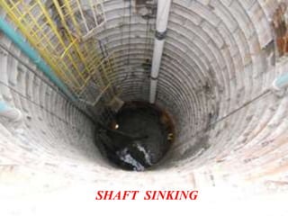
Shaft sinking 1
- 2. SHAFT SINKING Rajiv Gandhi College Of Engineering, Research & Technology PRESENTED BY : SUNIL D. WASADE Guided By Prof. B.K. KHADE H.O.D. Dr. M.D. Uttarwar Mining Engineering 2015-2016
- 3. CONTENTS Introduction Definition Aim of the project Objective of project Purpose of shaft sinking Design of mine shafts Preparatory work Conventional method of shaft sinking Conclusions Reference
- 4. INTRODUCTION In India, “MINING” industry is the backbone of India’s economy and energy. After agriculture mining is the second most important industry on which India’s economy is depend. Which helps in growth of any country in every aspects, because all existing industries are depend on mining. There is none of the industry which will replace to mining industry. Mining remains the most important player in the Indian industry, as well as Indian economy, Mining industry plays an important role in the development of nation. For underground mining working access should be very precious and reliable. There are many other access but most reliable option one access to excavate deep seated mineral body, that term is called as SHAFT. There is no other access existing which can replace shaft. So we will have to go through shaft. And for better shaft reliability we have to sink in better ways, that’s why SHINKING is very important. But there are many things would be considered. Then we can make better shaft.
- 5. Speedy and economical shaft sinking operation depends upon not only on actual sinking speeds but to a great extent also on the planning of the number and the size of the shaft of the hoisting equipment. the shaft sinking with permanent winding equipment offers some advantages due to the fact that in this case the transition from shaft sinking to tunneling requires less time and that in case the transition from shaft sinking to tunneling requires less time and that it is possible to dispense with the expenditures on the installation and dismantling of temporary equipment. Mechanical excavation methods are a step change in excavation performance and labour safety compared to drill and blast operations. In hard rock conditions, road headers cannot be used effectively, so disc cutting is the first For excavation of declines, tunnel boring machines (TBM) can be used in many cases. These provide, in certain rock conditions, considerably higher production rates compared to drill and blast excavation. Vertical shaft sinking machine (VSM) that allows excavating shallow shafts in soil a medium soft rock.
- 6. Definition Shaft: A vertical or inclined opening from surface for the conveyance of men, materials, hoisting ore, pumping water and providing ventilation. Sinking: The work in excavating a shaft. Shaft sinking: It may be described as an excavation of vertical or inclined opening from surface for conveyance of men, materials, ventilation, pumping water, in addition to hoisting ore and waste rock. It is also called Shaft Construction or Shaft Mining.
- 7. AIM OF THE PROJECT To study conventional and advanced techniques of shaft sinking. To increase the production and Productivity in method of working adopted to win the ore or mineral deposit by selecting appropriate and suitable available technologies for shaft sinking in Indian mines.
- 8. OBJECTIVE OF PROJECT Increasing the safety during sinking. The conditions inside the mine is needed to be improved The safe transport of the waste/ material/men. Increasing the production, efficiency and productivity of underground mine. To improve the ventilation arrangement of a mine. For this we require the construction of a new, sufficiently dimensioned shaft.
- 9. PURPOSE OF SHAFT SINKING shaft sinking is used for many purposes. To transport men and materials to and from underground Workings. For hoisting ore and waste from underground. To serve as intake and return airways for the mine (ventilation shaft). To access an ore body These shafts are used in applications such as hydro electric projects, water supply, waste water shafts and tunnel projects. Drilled shaft machine is used in such process, where it consists of special type of units that are used in both stable and unstable soils. Storage of nuclear waste Temporary storage and treatment of sewage
- 10. DESIGN OF MINE SHAFTS Shafts play a major role in the general planning of mine development, their location is usually pre-determined. The location of a shaft can be changed when adverse geotechnical site conditions are encountered. The design of mine shaft is an iterative process, which requires several variables and options to be considered in order to arrive at an economic decision. The economic decision is arrived at by comparing the net present values (NPV) and internal rate of return (IRR) from the different options considered in the optimization process. The option with the most attractive financial option is then selected. The design parameters mentioned above include, but are not necessarily limited to the following: depth of shaft, ore and waste tonnage to be handled, shift handling (work force), materials handling, advance machines used, ventilation requirements, capital costs, operating costs, and of course the selling price of the mineral commodity. The finished dia. Of shaft varies from 4.2m to 6.7m.
- 11. PREPARATORY WORK SURFACE PLANT AND EQUIPMENT REQUIRED FOR SINKING steam boilers and diesel engine for winding engine, pump etc. unless electrical power is available. winding engine and winders fitted with locked coil ropes. steel headgear. The headgear may be temporary nature and after the sinking is over, it is replaced by a permanent headgear and permanent winders to suit the output. double drum winches for Walling scaffold, and other winches for lighting cable, pump suspension rope and pump cable. air compressors for jackhammer drill used for drilling into rock and other compressed air operated equipment. Fan of nearly 300m3 per min capacity. generator with diesel or steam engine for lighting. folding doors to cover the shaft top. shaft centering arrangement. signaling arrangement from pit bottom to pit top and form pit top to winding engine. For disposal of debris, chutes, buckets, and tipping tubs with tramline etc. Workshop including smithly shop, mortar mill and other usual machines.
- 13. CONVENTIONAL METHOD OF SHAFT SINKING 1. Drilling 2. Blasting 3.Mucking and Hoisting 4. Support or shaft lining 5. Auxiliary operations: a) Dewatering b) Ventilation c) Lighting or illumination d) Shaft centering
- 14. Excavation method Drilling & blasting: A shaft is constructed by drilling holes and filling them with explosives. Using this method, drilling and blasting can sink around 5-10 metres in one blast. This is very labour-intensive, unsafe and has high running costs. The most viable alternative for shafts up to 100m in length. .
- 15. Mucking: The operation of loading broken rock by hand or machine, usually in shafts or tunnels. Note: Muck, any useless material produced in mining. mucking out cuttings from the bottom of the shaft. Usually this would require some skip-hoisting, bucket- hoisting or clam-shell-grab equipment
- 16. s
- 17. CRYDERMAN MUCKER
- 18. CACTUS GRAB
- 19. Wall supporting methods Rock bolting and meshing A wire mesh is fastened to the walls with evenly spaced rock bolts. Rock bolting is a commonly used, cheap method. The rock-bolts increase normal stresses on joints so that shear failure along joints becomes more difficult. Often rock bolts and mesh are used as a basis for shotcreting. Water in-flow during shotcreting severely reduces the quality of shotcrete.
- 21. LINING Basically there are two types of lining: Temporary and Permanent. The make of water and strength of the strata through which the sinking operation is to be carried out govern the choice In some situations temporary support is not required, whereas in others, it becomes essential to protect the crew and equipment from any side fall
- 22. TEMPORARY LINING
- 23. These consists of steel skeleton rings, say 15cm *12.5cm ,made in segments 62 to 68 m long and joined together by bolted lap joints alternatively, the rings may be of channel section for greater strength and joint by fish plate. The first ring is anchored by change to a timber frame erected across the shaft top or to steel rails driven into ground at a safe distance, one chain to each segment. Subsequent rings are hung from the one above by s- shaped hangers of 12.5 cm round or square steel and 1.45 to 1.5 m long. Every fourth ring is supported additionally by long steel pins driven into the shaft sides. Behind the rings are placed 15cm*2.5cm timber boards to form a close lining around the shaft and these are wedged tightly into position. Alternatively, steel backing sheets, some 0.6 m wide, may be used in place of timber. Where necessary, a close lining of pointed timber or steel piles may be driven down behind the rings to give support in advance of the excavation TEMPORARY LINING
- 24. PERMANENT LINING
- 25. Sinking is continued for a depth of several feet into the strong sandstone (blasting being required) to provide the solid foundation for the permanent concrete lining , the lower portion being widened out to enable a wedge shape curb to be formed . The first shuttering is then assembled and carefully levelled and centered by means of spirit level and centered line and radius rod. Behind the shuttering is added, a base of small debris and sand,(followed sometime by floret board covered with brattice cloth)is prepared to receive concrete. The ring is now filled with well rammed concrete, another ring of shuttering is added, and the process is continued ring by ring until concreting is completed. All the temporary supports are removed as the walling rises. During walling operation a temporary scaffold must be provided which can be raised or lowered by chain blocks slung by ropes or chains from girders placed across the shaft top and resting on the long timbers to distribute the weights. PERMANENT LINING
- 26. CONCLUSIONS In day to day life, demands of mineral is increasing and for fulfillment of this we would extracted more minerals by increasing production and productivity of Indian mines working. The production of opencast mining is greater than underground mines but shallow depth reserves are being depleted, for what mineral have to extracted from underground by underground method. . But most of the mineral reserves are situated at great depth. For minerals extraction from underground drives access through shaft. And to drives shaft, sinking is most important aspect. So we have to adopt best sinking methods so that cost of sinking will be reduce and sinking work will be done at faster rate to achieve the targeted production. For better sinking methods we studied the various Shaft Sinking methods. After studying, found that, the advanced mechanical excavations systems can have significant advantages over conventional drill and blast methods for sinking of shafts in many different aspects. Advanced mechanical excavation systems allow for a significantly enhanced level of productivity and safety due to the high degree of mechanization and
- 27. After studying case studies of two mines i.e Mansar and Balaghat mine in India where the shaft sinking was carried out recently by conventional shaft sinking methods techniques for the purpose of shaft sinking . The shaft of Mansar and Balaghat mines have made by Conventional Shaft sinking method but if this shaft would have been sunk with the advanced technologies like VSM and Shaft borer the production rate would have been raised to 30 % (Marks, 2002) with the sophisticated usage of manpower, increasing safety and reducing cost of capital on shaft sinking with less time required for sinking same length of shaft. Most reliable we can call that the advance sinking methods eliminates the usage of tedious method of Drilling and Blasting which is most critical to accidents with respect to safetyin mines. This mechanized method can also be applied for widening and deepening of existing shafts. But there are some natural and technical problems, of using advanced techniques in India, regarding with natural and technical condition in India such as geology, ground condition, required capital cost, operating cost, environment, suitability of techniques with Indian mining atmosphere, lack of knowledge
- 28. REFERENCE 1. Dinesh Baliga, B-mechanised Shaft Sinking – JI. Of Mine, Metal And Fuels And Special Number 1972. 2. Chatterjee, S K Et Al- The Development Of Base Metal Mine – Techniques Employed At Zawar Mines – Ji. Of Mine, Metal And Fuels And Special Number 1972. 3. Karwande, V L And Paranjpe D V – Mechanised Shaft Sinking At Singareni Collieries Ltd – Indian Mining And Engg. Journal, Special Number 1968. 4. Nath P D – Sinking Through Running Sand - Indian Mining And Engg. Journal, Special Number 1968. 5. Heinrich R. Gierke, Dulmen – Design Of Shaft ,Shaft Sinking – Symposium In Ranchi, Coal Expansion In India, 21-23 November 1983. 6. Walter Von Der Linden –N Shaft Sinking In Theory And Actual Performance - Ji. Of Mine, Metal And Fuels And Special Number 1962. 7. Mankovsky G I – Development Of Shaft Sinking Techniques In The Ussr - Ji. Of Mine, Metal And Fuels And Special Number 1962.