Chip Scale Pkg
•
0 likes•98 views

This document discusses the development of a 6-24 GHz mixer in a novel chip-scale package using 0.25um enhancement mode PHEMT technology. Key advantages of the chip-scale package include eliminating die assembly steps, reducing parasitics, and enabling a thinner package for improved thermal dissipation. Measurement results show the uncapped mixer has a conversion loss of ~9dB up to 22GHz and an IIP3 of +19dBm, while the capped mixer has slightly higher loss and lower IIP3. Isolation measurements were over 35dB for LO-RF and 40dB for LO-IF. This represents the first reported chip-scale packaged mixer.

Recommended
More Related Content
What's hot
What's hot (20)
Viewers also liked
Viewers also liked (20)
Similar to Chip Scale Pkg
Similar to Chip Scale Pkg (20)
Chip Scale Pkg
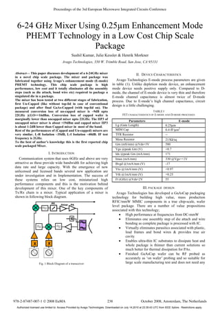
- 1. 6-24 GHz Mixer Using 0.25µm Enhancement Mode PHEMT Technology in a Low Cost Chip Scale Package Sushil Kumar, Julie Kessler & Henrik Morkner Avago Technologies, 350 W. Trimble Road, San Jose, CA 95131 Abstract— This paper discusses development of a 6-24GHz mixer in a novel chip scale package. The mixer and package was fabricated together using Avago’s enhancement mode (E-mode) PHEMT technology. This chip scale package is high performance, low cost and it totally eliminates all the assembly steps (such as die attach, bond wire etc) required to package a singulated die in a package. The mixer has been tested at two different stages of fabrication, first Un-Capped (like without top-lid in case of conventional package) and after final GaAs-Capped (with top-lid on). The measured conversion loss of un-capped mixer is ~9dB upto 22GHz @LO=+16dBm. Conversion loss of capped wafer is marginally lower than uncapped mixer upto 22GHz. The IIP3 of uncapped mixer mixer is about +19dBm and capped mixer IIP3 is about 1-2dB lower than Capped mixer in most of the band. Rest of the performances of (Capped and Un-capped) mixers are very similar. L-R Isolation ~35dB, L-I Isolation ~40dB. IF test frequency is 2GHz. To the best of author’s knowledge this is the first reported chip scale packaged Mixer. I. INTRODUCTION Communication system that uses 6GHz and above are very attractive as these provide wide bandwidth for achieving high data rate and large capacity. With the emergence of new unlicensed and licensed bands several new application are under investigation and in Implementation. The success of these systems relies on low cost, miniaturized high performance components and this is the motivation behind development of this mixer. One of the key components of Tx/Rx chain is a mixer. Typical application of a mixer is shown in following block diagram. Fig. 1 Block Diagram of a transceiver II. DEVICE CHARACTERISTICS Avago Technologies E-mode process parameters are given in table (1). Unlike depletion mode device, an enhancement mode device needs positive supply only. Compared to D- mode, the channel of E-mode device is very thin and therefore E-mode channel capacitance is almost twice of D-mode process. Due to E-mode’s high channel capacitance, circuit design is a little challenging. TABLE I FET CHARACTERISTICS OF E-MODE AND D-MODE PROCESSES Parameters E-mode Lg (Gate Length) 0.25μm MIM Cap 0.4 fF/μm2 TFR Resistor -- Mesa Resistor 213Ω/sq Gm (mS/mm) @Vds=3V 580 Vgs @peak Gm (V) +0.7 Ids @peak Gm (mA/mm) 171 Imax (mA/mm) 330 @Vgs=+1V Bvgd @1mA/mm (V) -17 Vto @1mA/mm (V) +0.97 Vth @1mA/mm (V) +0.25 Ft (GHz) @Vds=2V 55 III. PACKAGE DESIGN Avago Technologies has developed a GaAsCap packaging technology for building high value, mass production RFIC/mmW MMIC components in a true chip-scale, wafer level package. There are a number of value propositions associated with this technology; • High performance at frequencies from DC-mmW • Eliminates one assembly step of die attach and wire bonding as complete package is processed with IC. • Virtually eliminates parasitics associated with plastic, lead frames and bond wires & provides true air cavity • Enables ultra-thin IC substrates to dissipate heat and whole package is thinner than current solutions so much better for thermal dissipation for PAs. • Finished GaAsCap wafer can be RF probed as accurately as ‘on wafer’ probing and so suitable for large scale manufacturing test and does not need any LNA XX Driver PA Att. LNA XX XX Driver PA Att. 978-2-87487-007-1 © 2008 EuMA October 2008, Amsterdam, The Netherlands Proceedings of the 3rd European Microwave Integrated Circuits Conference 238 Authorized licensed use limited to: Access Provided by Avago Technologies. Downloaded on July 14,2010 at 23:35:43 UTC from IEEE Xplore. Restrictions apply.
- 2. PCB or custom test fixture/contactor board for testing. • Estimated cost is $0.10/mm2 ) even at mmW frequencies. A chip scale (GaAsCap) wafer is composed of a pair of bonded GaAs wafers, in which all the I/O’s are routed through Vias to the backside of the device wafer. The combination of the gasket and the cap wafer provides an air cavity, structural and protection for the device wafer. When the wafer is sawn between the gaskets, it literally becomes thousands of individually packaged parts. Photograph in fig. (2) is a finished GaAsCap wafer. Fig. 2 Photograph of a finished GaAsCap wafer. Figure (3) illustrates a cross-sectional view of a GaAsCap wafer. The base wafer is a standard processed GaAs wafer. The backside vias serve as I/O and ground pads for the package. The backside metal is plated thick enough to ensure adequate coverage in the bottom of the vias without inhibiting the use of standard solder pastes in assembly. The cap wafer provides an air cavity, protection for the devices, and enough structural support to allow thinning of the device wafer to 1.5 mils thickness. Fig. 3 Cross-sectional view of a GaAsCap wafer. IV. CIRCUIT DESIGN The designed mixer is based on single balance design. S-D connected FET has been used as diode. It has a LO balun that feeds diode and mixes with RF/IF frequency to generate desired IF/RF frequency as an down/up converter. A diplexer has been used for RF/IF. Several Momentum simulations have been run to optimize the performance of the LO balun. This balun provides amplitude balance ±0.5dB and phase balance ±0.5o from 5-25GHz. Use of 180o hybrids ensures excellent L- R isolation and eliminates or minimizes the need of a band pass filter to filter out LO power at R-port. Design of LO balun is based on Marchand technique. To reduce the chip size the balun has been folded into rectangular spiral shape. In addition to Balun entire layout has also been simulated using ADS Momentum to take into account all coupling among close proximity traces and all sorts of junction discontinuities. The insertion loss of low pass section (IF) of diplexer is <0.5dB from DC-3GHz and the insertion loss of high pass section (RF) is <1dB from 5-25GHz. Such low loss diplexer and excellent amplitude and phase matched Balun are key to this mixer low conversion loss and very wide band performance. Simplified schematic of Mixer is shown in fig.4. Fig. 4 Simplified Schematic of Mixer. The photograph of mixer chips developed is shown in fig. (5a,b). The GaAsCap package footprint is 2mm x 2mm. (a) (b) Fig. 5 (a) Top View of Un-capped Package. (b) Bottom view of Un- Capped/GaAs-Capped Package. V. MEASURED PERFORMANCE The Un-Capped and GaAs-capped mixers has been soldered on high frequency Roger PCB board and characterized in connectorized PCB media as shown in fig.6(a,b,c). Measured performance of mixer includes all losses such as connectors, PCB trace. This loss is of the order of 0.2-1.5dB from DC-25GHz. The measured mixers (UnCapped & GaAs-Capped) performance is shown from fig.(7)- fig.(12) as an Up- Converter. The down conversion performance is better or similar to Up-conversion. The LO (frequency) = (RF-IF)/2 GHz and IF=2GHz. Fig.(7) shows the measured uncapped mixer C.L. at Plo=+14 to +20dB. It shows 8.5-10dB conversion loss from 5- 24GHz @ Plo=+16dBm. Wafer Small area of a Wafer Singulated GaAsCap die Cap wafer (GaAs) Base Backside Via Gasket Gasket Backside Via Balun DiplexerLO RF IF GND LO IF RF 239 Authorized licensed use limited to: Access Provided by Avago Technologies. Downloaded on July 14,2010 at 23:35:43 UTC from IEEE Xplore. Restrictions apply.
- 3. (a) (b) (c) Fig. 6 (a) Photograph of Un-Capped Pkg in a Test Fixture. (b) Top View of Un-capped Package in fixture. (c) Top View of GaAs-capped Package in fixture. Fig. 7 Up-Conversion Loss of an Un-Capped mixer Fig. 8 Up-Conversion Loss of an GaAs-Capped mixer Fig.(8) shows C.L. of GaAs-Capped mixer at Plo=+14 to +20dB. GaAs-Capped mixer has slightly higher loss than Un- Capped mixer. Fig.(9) & Fig.(10) shows the measured IIP3 of Un-Capped & GaAs-Capped mixer in fixture. It can be seen from this measurement that IIP3 fluctuates significantly with frequency. This behavior attributes of RF/IF circuit impedance variation. This impedance variation produces different load impedance at harmonics termination of mixer. Also, the IIP3 of GaAs- Capped mixer is lower than Un-Capped mixer. The reason for GaAs-Capped mixer performance degradation compared to Un-Capped mixer is due to GaAs-Cap lid close proximity affect. Fig. 9 Up-Conversion IIP3 of an Un-Capped mixer Fig. 10 Up-Conversion IIP3 of an GaAs-Capped mixer 0 2 4 6 8 10 12 14 16 18 20 6 8 10 12 14 16 18 20 22 24 RF Freq. (GHz) C.L.(dB) LO=+14dBm LO=+16dBm LO=+18dBm LO=+20dBm GaAs-Capped 0 5 10 15 20 25 30 6 8 10 12 14 16 18 20 22 24 RF Freq. (GHz) IIP3(dBm) LO=+14dBm LO=+16dBm LO=+18dBm LO=+20dBm 0 5 10 15 20 25 30 6 8 10 12 14 16 18 20 22 24 RF Freq. (GHz) IIP3(dBm) LO=+14dBm LO=+16dBm LO=+18dBm LO=+20dBm 0 2 4 6 8 10 12 14 16 18 20 6 8 10 12 14 16 18 20 22 24 RFFreq. (GHz) C.L.(dB) LO=+14dBm LO=+16dBm LO=+18dBm LO=+20dBm Un-Capped The Power leakage and Isolation behaviors of Un-Capped & GaAs-Capped mixer are quite similar so they are shown as a one mixer measurement in fig.(11) & (12). 240 Authorized licensed use limited to: Access Provided by Avago Technologies. Downloaded on July 14,2010 at 23:35:43 UTC from IEEE Xplore. Restrictions apply.
- 4. Fig. 11 L-R Isolation of an Un-Capped/GaAs-Capped mixer 30 35 40 45 50 55 5 6 7 8 9 10 11 12 13 14 15 16 17 18 19 20 LO Frequency (GHz) L-IIsolation(dB) Plo=+10 Plo=+12 Plo=+14 Plo=+16 Plo=+18 Plo=+20 Plo=+22 Fig. 12 L-I Isolation of an Un-Capped/GaAs-Capped mixer VI. CONCLUSIONS A low cost, broadband high performance mixer in a novel package has been developed. This package fabrication technique made it possible to integrate the package as a MMIC fab process step and thus totally eliminated and die-to-package assembly complexity, time and cost. ACKNOWLEDGMENT Authors are thankful to Avago Technologies Fab team for fabrication of the designed mixer. Authors are grateful to Hue B. Tran for doing all testing. REFERENCES [1] S. Kumar, M. Vice, H. Morkner, W. Lam, “Enhancement mode GaAs PHEMT LNA with Linearity Control (IP3) and phased matched Mitigated Bypass Switch and Differential Active Mixer,” 2003 IEEE MTT-S Digest, pp. 1577-1580, June 2003. [2] H. Morkner, S. Kumar, M. Vice, “ A 18-45GHz Double Balanced Mixer with Integrated LO Amplifier and unique suspended Broadside coupled Balun, IEEE GaAs Integrated Circuit Symposium 2003, 25th Annual Technical Digest, USA, Nov. 2003, pp 1577-1580. [3] Trantella C.J., “Ultra small MMIc Mixers for K and Ka band Communications .” 2000 IEEE MTT-S digest pp 647-650. 20 25 30 35 40 45 50 55 60 5 6 7 8 9 10 11 12 13 14 15 16 17 18 19 20 LO Frequency (GHz) L-RIsolation(dB) Plo=+10 Plo=+12 Plo=+14 Plo=+16 Plo=+18 Plo=+20 Plo=+22 241 Authorized licensed use limited to: Access Provided by Avago Technologies. Downloaded on July 14,2010 at 23:35:43 UTC from IEEE Xplore. Restrictions apply.