SlideShare a Scribd company logo
1 of 12
DTMF CONTROLLED ROBOT
This is the robot whose actions can be controlled by a mobile phone
from all over the world using the DTMF signaling.
Use of mobile phones for robotic controls provides working range as
large as the coverage area of the service provider and no interference
with other controllers.
Block diagram
DTMF Controlled Robot
PROJECT OVERVIEW
In this project, the robot is controlled by a mobile phone that makes a
call to the mobile phone attached to the robot. In the course of a call, if
any button is pressed, a tone corresponding to the button pressed is
heard at the other end of the call. This tone is called DTMF (dual-tone-
multiple-frequency).The robot perceives this DTMF tone with the help
of the phone stacked in the robot. The received tone is processed by the
microcontroller residing on the Arduino UNO board with the help of
DTMF decoder IC (MT8870). The decoder decodes the DTMF tone
into its equivalent binary digit and this binary number is sent to the
microcontroller. The microcontroller is programmed to take a decision
for any given input and outputs its decision to motor drivers in order to
drive the motors in forward direction or backward direction or turn. The
mobile phone that makes a call to mobile phone stacked in the robot act
as a remote.
DTMF
DTMF (Dual tone multi frequency) as the name suggests uses a
combination of two sine wave tones to represent a key dialed on a
pushbutton or DTMF keypad.
These tones are called row and column frequencies as they correspond
to the layout of a telephone keypad.
DTMF keypad layout
A DTMF keypad (generator or
encoder) generates a sinusoidal
tone which is mixture of the row
and column frequencies. The row
and column frequencies
corresponding to a DTMF keypad have been indicated in the above
figure.
DTMF tones are able to represent one of the 16 different states or
symbols on the keypad.
Hardware components required and their purpose:
1. Arduino UNO board
2. Transmitter and receiver mobile phones
3. DTMF decoder IC (MT8870)
4. DC motor
5. Motor driver IC (L293D)
6. Wheels
7. Power adopter
 Arduino UNO board: This is the brain of this robot in which the
program is loaded to do the required functioning and is interfaced
with decoder IC and the motor driver to make the system work as
required.
 Transmitter and receiver mobile phones: Here the transmitting
phone is working as a remote and the receiving phone is attached
to the robot which receives the DTMF signals which are then fed to
decoder IC after converting them to electrical form through audio
jack.
 DTMF decoder IC (MT8870)
The decoder decodes the DTMF tone into its equivalent binary
digit and this binary number is sent to the microcontroller.
DTMF decoder IC (MT8870)
On pressing any key say key 1,
a combination of frequencies
1209 and 697 Hz will be
generated by keypad which is
fed to IC through sound
converter which in turn
produce the output 0001 (Q1,
Q2, Q3, Q4). Following
table shows output of
remaining keys.
MT8870 output
 DC Motor: This motor is controlled with DC voltages and can
move in forward and backward direction according to the polarity
of the voltage applied.
 Motor driver IC (L293D): Microcontrollers can’t supply the
current required by DC motor to run. So, to fulfill this requirement
these motor driver ICs are used.
DC motors with Driver IC
 Power adopter: This is used to give appropriate dc power supply
to microcontroller, driver IC sensors and the other passive
components of the robot.
 Wheels: In it three wheels are employed, two at rear end and one at
front end. Rear wheels are attached with the motors and also
control the steering of robot. Front wheel is the loose steered wheel
which moves in the direction of the pressure applied to it.
Overview:
Top view of robot
Description
The robot is controlled by a mobile phone that makes call to the
mobile phone attached to the robot and in the course of the call, if any
button is pressed the corresponding DTMF freq. will be heard at the
other end.
DTMF assigns a specific frequency (consisting of two separate tones)
to each key that it can easily be identified by the electronic circuit.
The signal generated by the DTMF encoder is the direct algebraic
submission, in real time of the amplitudes of two sine(cosine) waves
of different frequencies, for example: pressing key5 will send a tone
made by adding 1336hz and 770hz to the other end of the mobile.
The received tone is processed by the atmega8 microcontroller with
the help of DTMF decoder (MT8870). The decoder decodes the
DTMF tone in to its equivalent binary digit and this binary number is
send to the microcontroller.
The microcontroller is preprogrammed to take a decision for any
given input and outputs its decision to motor drivers in order to drive
the motors for forward or backward motion or a turn.
Program:
/*DTMF pins Q1-4 are attached with pins 9-12
left motor attached to pin 5,6 and
right motor attached to pin 7,8 and
*/
int q1=9;
int q2=10;
int q3=11;
int q4=12;
void setup() {
//Initialize serial and wait for port to open:
Serial.begin(9600);
pinMode(q1, INPUT);
pinMode(q2, INPUT);
pinMode(q3, INPUT);
pinMode(q4, INPUT);
pinMode(5, OUTPUT);
pinMode(6, OUTPUT);
pinMode(7, OUTPUT);
pinMode(8, OUTPUT);
}
void loop()
{
int v1,v2,v3,v4,value;
v1 = digitalRead(q1);
v2 = digitalRead(q2);
v3 = digitalRead(q3);
v4 = digitalRead(q4);
value=((v4<<3)|(v3<<2)|(v2<<1)|(v1));
switch(value)
{
case 0X02:
{
digitalWrite(6, LOW);
digitalWrite(8, LOW);
digitalWrite(5, HIGH);
digitalWrite(7, HIGH); //switch on both
break;
}
case 6: //RIGHT turn
{
digitalWrite(5, HIGH);
digitalWrite(7, LOW);
digitalWrite(6, LOW);
digitalWrite(8, LOW); //switch on only LEFT motor move to RIGHT
break;
}
case 4: //LEFT turn
{
digitalWrite(5, LOW);
digitalWrite(7, HIGH);
digitalWrite(6, LOW);
digitalWrite(8, LOW);
//switch on only RIGHT motor move to LEFT
break;
}
case 8:
{
digitalWrite(5, LOW);
digitalWrite(7, LOW);
digitalWrite(6, HIGH);
digitalWrite(8, HIGH); //both REVERSE
break;
}
default:
{
digitalWrite(5, LOW);
digitalWrite(7, LOW);
digitalWrite(6, LOW);
digitalWrite(8, LOW);
break;
}
}
}
Programming Digital I/O pins of Arduino UNO board:
 Each pin is controlled by three commands associated with it which are
designated as:
pinMode()
digitalWrite()
digitalRead()
 pinMode()
This configures the specified pin to behave either as an input or an output.
Syntax
pinMode(pin, mode)
Parameters
pin: the number of the pin whose mode you wish to set
mode: INPUT, OUTPUT.
Returns
None
Example
int ledPin = 13; // LED connected to digital pin 13
void setup()
{
pinMode(ledPin, OUTPUT); // sets the digital pin as output
}
void loop()
{
digitalWrite(ledPin, HIGH); // sets the LED on
delay(1000); // waits for a second
digitalWrite(ledPin, LOW); // sets the LED off
delay(1000); // waits for a second
}
 digitalWrite()
Write a HIGH or a LOW value to a digital pin.
If the pin has been configured as an OUTPUT with pinMode(), its voltage
will be set to the corresponding value: 5V (or 3.3V on 3.3V boards) for
HIGH, 0V (ground) for LOW.
Syntax
digitalWrite(pin, value)
Parameters
pin: the pin number
value: HIGH or LOW
Returns
None
Example
Sets pin 13 to HIGH, makes a one-second-long delay, and sets the pin back to LOW.
int ledPin = 13; // LED connected to digital pin 13
void setup()
{
pinMode(ledPin, OUTPUT); // sets the digital pin as output
}
void loop()
{
digitalWrite(ledPin, HIGH); // sets the LED on
delay(1000); // waits for a second
digitalWrite(ledPin, LOW); // sets the LED off
delay(1000); // waits for a second
}
 digitalRead()
Reads the value from a specified digital pin, either HIGH or LOW.
Syntax
digitalRead(pin)
Parameters
pin: the number of the digital pin you want to read (int)
Returns
HIGH or LOW
Example
int ledPin = 13; // LED connected to digital pin 13
int inPin = 7; // pushbutton connected to digital pin 7
int val = 0; // variable to store the read value
void setup()
{
pinMode(ledPin, OUTPUT); // sets the digital pin 13 as output
pinMode(inPin, INPUT); // sets the digital pin 7 as input
}
void loop()
{
val = digitalRead(inPin); // read the input pin
digitalWrite(ledPin, val); // sets the LED to the button's value
}

More Related Content

What's hot

Fire fighting robot using arduino
Fire fighting robot using arduinoFire fighting robot using arduino
Fire fighting robot using arduinoNiranjan Kumar
 
Report on Night Vision Technology
Report on Night Vision Technology Report on Night Vision Technology
Report on Night Vision Technology RebekahSamuel2
 
DTMF Controlled Robot Car WITHOUT using MICROCONTROLLER
DTMF Controlled Robot Car  WITHOUT using MICROCONTROLLERDTMF Controlled Robot Car  WITHOUT using MICROCONTROLLER
DTMF Controlled Robot Car WITHOUT using MICROCONTROLLERVishwanath Neha
 
TV Remote control Home Appliances using Arduino(Infrared)
TV Remote control Home Appliances using Arduino(Infrared)TV Remote control Home Appliances using Arduino(Infrared)
TV Remote control Home Appliances using Arduino(Infrared)sushil roy thalakayala
 
Black Box for a Car
Black Box for a CarBlack Box for a Car
Black Box for a Carsubrat manna
 
Project report on embedded system using 8051 microcontroller
Project  report on embedded system using 8051 microcontrollerProject  report on embedded system using 8051 microcontroller
Project report on embedded system using 8051 microcontrollerVandna Sambyal
 
Smart shopping trolley using rfid and remote controlling
Smart shopping trolley using rfid and remote controllingSmart shopping trolley using rfid and remote controlling
Smart shopping trolley using rfid and remote controllingPranav Veerani
 
Missile detection and automatic destroy system
Missile detection and automatic destroy system Missile detection and automatic destroy system
Missile detection and automatic destroy system LokeshLavakusha
 
Project report on home automation using Arduino
Project report on home automation using Arduino Project report on home automation using Arduino
Project report on home automation using Arduino AMIT SANPUI
 
EC8562 DSP Viva Questions
EC8562 DSP Viva Questions EC8562 DSP Viva Questions
EC8562 DSP Viva Questions ssuser2797e4
 
RFID BASED ATTENDANCE SYSTEM PPT
RFID BASED ATTENDANCE SYSTEM PPTRFID BASED ATTENDANCE SYSTEM PPT
RFID BASED ATTENDANCE SYSTEM PPTnikhilpatewar
 
Summer Training Program Report On Embedded system and robot
Summer Training Program Report On Embedded system and robot Summer Training Program Report On Embedded system and robot
Summer Training Program Report On Embedded system and robot Arcanjo Salazaku
 
Fire fighting Robot
Fire fighting RobotFire fighting Robot
Fire fighting RobotAnjan991
 

What's hot (20)

green house monitoring system
green house monitoring systemgreen house monitoring system
green house monitoring system
 
Fire fighting robot using arduino
Fire fighting robot using arduinoFire fighting robot using arduino
Fire fighting robot using arduino
 
MILITARY ROBOT BASED ON IOT
MILITARY ROBOT BASED ON IOTMILITARY ROBOT BASED ON IOT
MILITARY ROBOT BASED ON IOT
 
Report on Night Vision Technology
Report on Night Vision Technology Report on Night Vision Technology
Report on Night Vision Technology
 
DTMF Controlled Robot Car WITHOUT using MICROCONTROLLER
DTMF Controlled Robot Car  WITHOUT using MICROCONTROLLERDTMF Controlled Robot Car  WITHOUT using MICROCONTROLLER
DTMF Controlled Robot Car WITHOUT using MICROCONTROLLER
 
TV Remote control Home Appliances using Arduino(Infrared)
TV Remote control Home Appliances using Arduino(Infrared)TV Remote control Home Appliances using Arduino(Infrared)
TV Remote control Home Appliances using Arduino(Infrared)
 
Mobile detector
Mobile detectorMobile detector
Mobile detector
 
Black Box for a Car
Black Box for a CarBlack Box for a Car
Black Box for a Car
 
Project report on embedded system using 8051 microcontroller
Project  report on embedded system using 8051 microcontrollerProject  report on embedded system using 8051 microcontroller
Project report on embedded system using 8051 microcontroller
 
Smart shopping system using rfid
Smart shopping system using rfidSmart shopping system using rfid
Smart shopping system using rfid
 
Smart shopping trolley using rfid and remote controlling
Smart shopping trolley using rfid and remote controllingSmart shopping trolley using rfid and remote controlling
Smart shopping trolley using rfid and remote controlling
 
Missile detection and automatic destroy system
Missile detection and automatic destroy system Missile detection and automatic destroy system
Missile detection and automatic destroy system
 
Bluetooth controlled robot
Bluetooth controlled robotBluetooth controlled robot
Bluetooth controlled robot
 
Project report on home automation using Arduino
Project report on home automation using Arduino Project report on home automation using Arduino
Project report on home automation using Arduino
 
EC8562 DSP Viva Questions
EC8562 DSP Viva Questions EC8562 DSP Viva Questions
EC8562 DSP Viva Questions
 
Fire Fighting Robotic Vehicle
Fire Fighting Robotic VehicleFire Fighting Robotic Vehicle
Fire Fighting Robotic Vehicle
 
RFID BASED ATTENDANCE SYSTEM PPT
RFID BASED ATTENDANCE SYSTEM PPTRFID BASED ATTENDANCE SYSTEM PPT
RFID BASED ATTENDANCE SYSTEM PPT
 
Summer Training Program Report On Embedded system and robot
Summer Training Program Report On Embedded system and robot Summer Training Program Report On Embedded system and robot
Summer Training Program Report On Embedded system and robot
 
Fire fighting Robot
Fire fighting RobotFire fighting Robot
Fire fighting Robot
 
Shadow alarm
Shadow alarm Shadow alarm
Shadow alarm
 

Viewers also liked

Cell Phone Operated Robot
Cell Phone Operated RobotCell Phone Operated Robot
Cell Phone Operated RobotAniket Bhor
 
DTMF Mobile Operated Robot using Atmega16
DTMF Mobile Operated Robot using Atmega16DTMF Mobile Operated Robot using Atmega16
DTMF Mobile Operated Robot using Atmega16Prashant Saini
 
Home Automation using DTMF
Home Automation using DTMFHome Automation using DTMF
Home Automation using DTMFPrashant Jaitly
 
Cell phone operated robot synopsis
Cell phone operated robot synopsisCell phone operated robot synopsis
Cell phone operated robot synopsisgopal002
 
Project on gsm based mobile controlling robot
Project on gsm based mobile controlling robotProject on gsm based mobile controlling robot
Project on gsm based mobile controlling robotAnwarul Islam Mithu
 
Cell Phone Controlled Home Automation System using DTMF Technology
Cell Phone Controlled Home Automation System using DTMF TechnologyCell Phone Controlled Home Automation System using DTMF Technology
Cell Phone Controlled Home Automation System using DTMF TechnologyTaufique Sekh
 
land rover robot control using GSM technology
land rover robot control using GSM technologyland rover robot control using GSM technology
land rover robot control using GSM technologyJOLLUSUDARSHANREDDY
 
Ppt land rover
Ppt land roverPpt land rover
Ppt land roverAshu0711
 
DTMF based Home Automation System
DTMF based Home Automation SystemDTMF based Home Automation System
DTMF based Home Automation SystemDaksh Raj Chopra
 
multiple input control by sms using GSM technology
multiple input control by sms using GSM technologymultiple input control by sms using GSM technology
multiple input control by sms using GSM technologySachin Singh
 
Home Automation System using Arduino and Android
Home Automation System using Arduino and AndroidHome Automation System using Arduino and Android
Home Automation System using Arduino and AndroidMuhammad Ayesh
 
Cell phone operated robot
Cell phone operated robotCell phone operated robot
Cell phone operated robotAbhishek Rawat
 
project presentation on cell phone operated land rover
project presentation on cell phone operated land roverproject presentation on cell phone operated land rover
project presentation on cell phone operated land roversunanda kothari
 
Obstacle Detctor Robot report
Obstacle Detctor Robot reportObstacle Detctor Robot report
Obstacle Detctor Robot reportNikita Kaushal
 
Arduino Based Home Automation (2003) (1003018)
Arduino Based Home Automation (2003) (1003018)Arduino Based Home Automation (2003) (1003018)
Arduino Based Home Automation (2003) (1003018)Rappy Saha
 
HOME AUTOMATION USING ARDUINO
HOME AUTOMATION USING ARDUINOHOME AUTOMATION USING ARDUINO
HOME AUTOMATION USING ARDUINOEklavya Sharma
 
home appliance control using gsm
home appliance control using gsmhome appliance control using gsm
home appliance control using gsmChinmoy Jena
 

Viewers also liked (20)

Cell Phone Operated Robot
Cell Phone Operated RobotCell Phone Operated Robot
Cell Phone Operated Robot
 
DTMF Robot
DTMF RobotDTMF Robot
DTMF Robot
 
DTMF Mobile Operated Robot using Atmega16
DTMF Mobile Operated Robot using Atmega16DTMF Mobile Operated Robot using Atmega16
DTMF Mobile Operated Robot using Atmega16
 
Home Automation using DTMF
Home Automation using DTMFHome Automation using DTMF
Home Automation using DTMF
 
Cell phone operated robot synopsis
Cell phone operated robot synopsisCell phone operated robot synopsis
Cell phone operated robot synopsis
 
Project on gsm based mobile controlling robot
Project on gsm based mobile controlling robotProject on gsm based mobile controlling robot
Project on gsm based mobile controlling robot
 
Importance of automation
Importance of automationImportance of automation
Importance of automation
 
Cell Phone Controlled Home Automation System using DTMF Technology
Cell Phone Controlled Home Automation System using DTMF TechnologyCell Phone Controlled Home Automation System using DTMF Technology
Cell Phone Controlled Home Automation System using DTMF Technology
 
land rover robot control using GSM technology
land rover robot control using GSM technologyland rover robot control using GSM technology
land rover robot control using GSM technology
 
Ppt land rover
Ppt land roverPpt land rover
Ppt land rover
 
DTMF based Home Automation System
DTMF based Home Automation SystemDTMF based Home Automation System
DTMF based Home Automation System
 
multiple input control by sms using GSM technology
multiple input control by sms using GSM technologymultiple input control by sms using GSM technology
multiple input control by sms using GSM technology
 
Home Automation System using Arduino and Android
Home Automation System using Arduino and AndroidHome Automation System using Arduino and Android
Home Automation System using Arduino and Android
 
Cell phone operated robot
Cell phone operated robotCell phone operated robot
Cell phone operated robot
 
project presentation on cell phone operated land rover
project presentation on cell phone operated land roverproject presentation on cell phone operated land rover
project presentation on cell phone operated land rover
 
Obstacle Detctor Robot report
Obstacle Detctor Robot reportObstacle Detctor Robot report
Obstacle Detctor Robot report
 
Arduino Based Home Automation (2003) (1003018)
Arduino Based Home Automation (2003) (1003018)Arduino Based Home Automation (2003) (1003018)
Arduino Based Home Automation (2003) (1003018)
 
Gsm based home automation
Gsm based home automationGsm based home automation
Gsm based home automation
 
HOME AUTOMATION USING ARDUINO
HOME AUTOMATION USING ARDUINOHOME AUTOMATION USING ARDUINO
HOME AUTOMATION USING ARDUINO
 
home appliance control using gsm
home appliance control using gsmhome appliance control using gsm
home appliance control using gsm
 

Similar to Arduino dtmf controlled robot

Pankaj project report
Pankaj project reportPankaj project report
Pankaj project reportPankaj Rai
 
Cell Phone Operated Land Rover
Cell Phone Operated Land RoverCell Phone Operated Land Rover
Cell Phone Operated Land RoverSanjay Talukdar
 
Final Report11
Final Report11Final Report11
Final Report11sonu kumar
 
DTMF based home automation with ADRUINO
DTMF based home automation with ADRUINODTMF based home automation with ADRUINO
DTMF based home automation with ADRUINOFucck
 
Cell operated land rover robot
Cell operated land rover robotCell operated land rover robot
Cell operated land rover robotChetan Kataria
 
DTMF CONTROLLED ROBOT
DTMF CONTROLLED ROBOTDTMF CONTROLLED ROBOT
DTMF CONTROLLED ROBOTnarendra019
 
Mobile operated spy robot
Mobile operated spy robotMobile operated spy robot
Mobile operated spy robotKevin Nesamani
 
Mobile Phone Operated Dual-tone-multiple-frequency controlled Microcontroller...
Mobile Phone Operated Dual-tone-multiple-frequency controlled Microcontroller...Mobile Phone Operated Dual-tone-multiple-frequency controlled Microcontroller...
Mobile Phone Operated Dual-tone-multiple-frequency controlled Microcontroller...IOSRJEEE
 
Mobile Controlled Car
Mobile Controlled CarMobile Controlled Car
Mobile Controlled CarMalik Zaid
 
Cell Phone Controlled Home Automation System using DTMF Technology
Cell Phone Controlled Home Automation System using DTMF TechnologyCell Phone Controlled Home Automation System using DTMF Technology
Cell Phone Controlled Home Automation System using DTMF TechnologyTaufique Sekh
 
1444461651 p327 334
1444461651 p327 3341444461651 p327 334
1444461651 p327 334Alok Tiwari
 

Similar to Arduino dtmf controlled robot (20)

Mobile controll robot
Mobile controll robotMobile controll robot
Mobile controll robot
 
Pankaj project report
Pankaj project reportPankaj project report
Pankaj project report
 
Mobile controlled robot
Mobile controlled robotMobile controlled robot
Mobile controlled robot
 
Cell Phone Operated Land Rover
Cell Phone Operated Land RoverCell Phone Operated Land Rover
Cell Phone Operated Land Rover
 
DTM Decoder
DTM DecoderDTM Decoder
DTM Decoder
 
Final Report
Final ReportFinal Report
Final Report
 
Presentation1
Presentation1Presentation1
Presentation1
 
Final Report11
Final Report11Final Report11
Final Report11
 
final ppt2.pptx
final ppt2.pptxfinal ppt2.pptx
final ppt2.pptx
 
DTMF based home automation with ADRUINO
DTMF based home automation with ADRUINODTMF based home automation with ADRUINO
DTMF based home automation with ADRUINO
 
Cell operated land rover robot
Cell operated land rover robotCell operated land rover robot
Cell operated land rover robot
 
SURVEILLANCE ROBOT
SURVEILLANCE ROBOTSURVEILLANCE ROBOT
SURVEILLANCE ROBOT
 
DTMF CONTROLLED ROBOT
DTMF CONTROLLED ROBOTDTMF CONTROLLED ROBOT
DTMF CONTROLLED ROBOT
 
Mobile operated spy robot
Mobile operated spy robotMobile operated spy robot
Mobile operated spy robot
 
Mobile Phone Operated Dual-tone-multiple-frequency controlled Microcontroller...
Mobile Phone Operated Dual-tone-multiple-frequency controlled Microcontroller...Mobile Phone Operated Dual-tone-multiple-frequency controlled Microcontroller...
Mobile Phone Operated Dual-tone-multiple-frequency controlled Microcontroller...
 
ivr system
ivr systemivr system
ivr system
 
Mobile Controlled Car
Mobile Controlled CarMobile Controlled Car
Mobile Controlled Car
 
Cell Phone Controlled Home Automation System using DTMF Technology
Cell Phone Controlled Home Automation System using DTMF TechnologyCell Phone Controlled Home Automation System using DTMF Technology
Cell Phone Controlled Home Automation System using DTMF Technology
 
DTMF based load control
DTMF based load controlDTMF based load control
DTMF based load control
 
1444461651 p327 334
1444461651 p327 3341444461651 p327 334
1444461651 p327 334
 

More from UVSofts Technologies (14)

Arduino bluetooth controlled robot
Arduino bluetooth controlled robotArduino bluetooth controlled robot
Arduino bluetooth controlled robot
 
Vehicle tracting system
Vehicle tracting systemVehicle tracting system
Vehicle tracting system
 
GPS based tracking system
GPS based tracking systemGPS based tracking system
GPS based tracking system
 
Password based door locksystem
Password  based door locksystemPassword  based door locksystem
Password based door locksystem
 
Calculator
CalculatorCalculator
Calculator
 
Basic standard calculator
Basic standard calculatorBasic standard calculator
Basic standard calculator
 
Password based door locksystem
Password  based door locksystemPassword  based door locksystem
Password based door locksystem
 
Bluetooth controlled robot
Bluetooth controlled robotBluetooth controlled robot
Bluetooth controlled robot
 
Pc controlled robot
Pc controlled robotPc controlled robot
Pc controlled robot
 
Pc controlled robot
Pc controlled robotPc controlled robot
Pc controlled robot
 
Edge detector robot
Edge detector robotEdge detector robot
Edge detector robot
 
Line follower robot
Line follower robotLine follower robot
Line follower robot
 
Line follower robot
Line follower robotLine follower robot
Line follower robot
 
Edge detector & avoider robot
Edge detector & avoider robotEdge detector & avoider robot
Edge detector & avoider robot
 

Recently uploaded

Module-1-(Building Acoustics) Noise Control (Unit-3). pdf
Module-1-(Building Acoustics) Noise Control (Unit-3). pdfModule-1-(Building Acoustics) Noise Control (Unit-3). pdf
Module-1-(Building Acoustics) Noise Control (Unit-3). pdfManish Kumar
 
Turn leadership mistakes into a better future.pptx
Turn leadership mistakes into a better future.pptxTurn leadership mistakes into a better future.pptx
Turn leadership mistakes into a better future.pptxStephen Sitton
 
FUNCTIONAL AND NON FUNCTIONAL REQUIREMENT
FUNCTIONAL AND NON FUNCTIONAL REQUIREMENTFUNCTIONAL AND NON FUNCTIONAL REQUIREMENT
FUNCTIONAL AND NON FUNCTIONAL REQUIREMENTSneha Padhiar
 
STATE TRANSITION DIAGRAM in psoc subject
STATE TRANSITION DIAGRAM in psoc subjectSTATE TRANSITION DIAGRAM in psoc subject
STATE TRANSITION DIAGRAM in psoc subjectGayathriM270621
 
DEVICE DRIVERS AND INTERRUPTS SERVICE MECHANISM.pdf
DEVICE DRIVERS AND INTERRUPTS  SERVICE MECHANISM.pdfDEVICE DRIVERS AND INTERRUPTS  SERVICE MECHANISM.pdf
DEVICE DRIVERS AND INTERRUPTS SERVICE MECHANISM.pdfAkritiPradhan2
 
"Exploring the Essential Functions and Design Considerations of Spillways in ...
"Exploring the Essential Functions and Design Considerations of Spillways in ..."Exploring the Essential Functions and Design Considerations of Spillways in ...
"Exploring the Essential Functions and Design Considerations of Spillways in ...Erbil Polytechnic University
 
Input Output Management in Operating System
Input Output Management in Operating SystemInput Output Management in Operating System
Input Output Management in Operating SystemRashmi Bhat
 
Curve setting (Basic Mine Surveying)_MI10412MI.pptx
Curve setting (Basic Mine Surveying)_MI10412MI.pptxCurve setting (Basic Mine Surveying)_MI10412MI.pptx
Curve setting (Basic Mine Surveying)_MI10412MI.pptxRomil Mishra
 
Energy Awareness training ppt for manufacturing process.pptx
Energy Awareness training ppt for manufacturing process.pptxEnergy Awareness training ppt for manufacturing process.pptx
Energy Awareness training ppt for manufacturing process.pptxsiddharthjain2303
 
Mine Environment II Lab_MI10448MI__________.pptx
Mine Environment II Lab_MI10448MI__________.pptxMine Environment II Lab_MI10448MI__________.pptx
Mine Environment II Lab_MI10448MI__________.pptxRomil Mishra
 
Novel 3D-Printed Soft Linear and Bending Actuators
Novel 3D-Printed Soft Linear and Bending ActuatorsNovel 3D-Printed Soft Linear and Bending Actuators
Novel 3D-Printed Soft Linear and Bending ActuatorsResearcher Researcher
 
A brief look at visionOS - How to develop app on Apple's Vision Pro
A brief look at visionOS - How to develop app on Apple's Vision ProA brief look at visionOS - How to develop app on Apple's Vision Pro
A brief look at visionOS - How to develop app on Apple's Vision ProRay Yuan Liu
 
Cost estimation approach: FP to COCOMO scenario based question
Cost estimation approach: FP to COCOMO scenario based questionCost estimation approach: FP to COCOMO scenario based question
Cost estimation approach: FP to COCOMO scenario based questionSneha Padhiar
 
Forming section troubleshooting checklist for improving wire life (1).ppt
Forming section troubleshooting checklist for improving wire life (1).pptForming section troubleshooting checklist for improving wire life (1).ppt
Forming section troubleshooting checklist for improving wire life (1).pptNoman khan
 
TEST CASE GENERATION GENERATION BLOCK BOX APPROACH
TEST CASE GENERATION GENERATION BLOCK BOX APPROACHTEST CASE GENERATION GENERATION BLOCK BOX APPROACH
TEST CASE GENERATION GENERATION BLOCK BOX APPROACHSneha Padhiar
 
Gravity concentration_MI20612MI_________
Gravity concentration_MI20612MI_________Gravity concentration_MI20612MI_________
Gravity concentration_MI20612MI_________Romil Mishra
 
Comprehensive energy systems.pdf Comprehensive energy systems.pdf
Comprehensive energy systems.pdf Comprehensive energy systems.pdfComprehensive energy systems.pdf Comprehensive energy systems.pdf
Comprehensive energy systems.pdf Comprehensive energy systems.pdfalene1
 
US Department of Education FAFSA Week of Action
US Department of Education FAFSA Week of ActionUS Department of Education FAFSA Week of Action
US Department of Education FAFSA Week of ActionMebane Rash
 
Comparative study of High-rise Building Using ETABS,SAP200 and SAFE., SAFE an...
Comparative study of High-rise Building Using ETABS,SAP200 and SAFE., SAFE an...Comparative study of High-rise Building Using ETABS,SAP200 and SAFE., SAFE an...
Comparative study of High-rise Building Using ETABS,SAP200 and SAFE., SAFE an...Erbil Polytechnic University
 
2022 AWS DNA Hackathon 장애 대응 솔루션 jarvis.
2022 AWS DNA Hackathon 장애 대응 솔루션 jarvis.2022 AWS DNA Hackathon 장애 대응 솔루션 jarvis.
2022 AWS DNA Hackathon 장애 대응 솔루션 jarvis.elesangwon
 

Recently uploaded (20)

Module-1-(Building Acoustics) Noise Control (Unit-3). pdf
Module-1-(Building Acoustics) Noise Control (Unit-3). pdfModule-1-(Building Acoustics) Noise Control (Unit-3). pdf
Module-1-(Building Acoustics) Noise Control (Unit-3). pdf
 
Turn leadership mistakes into a better future.pptx
Turn leadership mistakes into a better future.pptxTurn leadership mistakes into a better future.pptx
Turn leadership mistakes into a better future.pptx
 
FUNCTIONAL AND NON FUNCTIONAL REQUIREMENT
FUNCTIONAL AND NON FUNCTIONAL REQUIREMENTFUNCTIONAL AND NON FUNCTIONAL REQUIREMENT
FUNCTIONAL AND NON FUNCTIONAL REQUIREMENT
 
STATE TRANSITION DIAGRAM in psoc subject
STATE TRANSITION DIAGRAM in psoc subjectSTATE TRANSITION DIAGRAM in psoc subject
STATE TRANSITION DIAGRAM in psoc subject
 
DEVICE DRIVERS AND INTERRUPTS SERVICE MECHANISM.pdf
DEVICE DRIVERS AND INTERRUPTS  SERVICE MECHANISM.pdfDEVICE DRIVERS AND INTERRUPTS  SERVICE MECHANISM.pdf
DEVICE DRIVERS AND INTERRUPTS SERVICE MECHANISM.pdf
 
"Exploring the Essential Functions and Design Considerations of Spillways in ...
"Exploring the Essential Functions and Design Considerations of Spillways in ..."Exploring the Essential Functions and Design Considerations of Spillways in ...
"Exploring the Essential Functions and Design Considerations of Spillways in ...
 
Input Output Management in Operating System
Input Output Management in Operating SystemInput Output Management in Operating System
Input Output Management in Operating System
 
Curve setting (Basic Mine Surveying)_MI10412MI.pptx
Curve setting (Basic Mine Surveying)_MI10412MI.pptxCurve setting (Basic Mine Surveying)_MI10412MI.pptx
Curve setting (Basic Mine Surveying)_MI10412MI.pptx
 
Energy Awareness training ppt for manufacturing process.pptx
Energy Awareness training ppt for manufacturing process.pptxEnergy Awareness training ppt for manufacturing process.pptx
Energy Awareness training ppt for manufacturing process.pptx
 
Mine Environment II Lab_MI10448MI__________.pptx
Mine Environment II Lab_MI10448MI__________.pptxMine Environment II Lab_MI10448MI__________.pptx
Mine Environment II Lab_MI10448MI__________.pptx
 
Novel 3D-Printed Soft Linear and Bending Actuators
Novel 3D-Printed Soft Linear and Bending ActuatorsNovel 3D-Printed Soft Linear and Bending Actuators
Novel 3D-Printed Soft Linear and Bending Actuators
 
A brief look at visionOS - How to develop app on Apple's Vision Pro
A brief look at visionOS - How to develop app on Apple's Vision ProA brief look at visionOS - How to develop app on Apple's Vision Pro
A brief look at visionOS - How to develop app on Apple's Vision Pro
 
Cost estimation approach: FP to COCOMO scenario based question
Cost estimation approach: FP to COCOMO scenario based questionCost estimation approach: FP to COCOMO scenario based question
Cost estimation approach: FP to COCOMO scenario based question
 
Forming section troubleshooting checklist for improving wire life (1).ppt
Forming section troubleshooting checklist for improving wire life (1).pptForming section troubleshooting checklist for improving wire life (1).ppt
Forming section troubleshooting checklist for improving wire life (1).ppt
 
TEST CASE GENERATION GENERATION BLOCK BOX APPROACH
TEST CASE GENERATION GENERATION BLOCK BOX APPROACHTEST CASE GENERATION GENERATION BLOCK BOX APPROACH
TEST CASE GENERATION GENERATION BLOCK BOX APPROACH
 
Gravity concentration_MI20612MI_________
Gravity concentration_MI20612MI_________Gravity concentration_MI20612MI_________
Gravity concentration_MI20612MI_________
 
Comprehensive energy systems.pdf Comprehensive energy systems.pdf
Comprehensive energy systems.pdf Comprehensive energy systems.pdfComprehensive energy systems.pdf Comprehensive energy systems.pdf
Comprehensive energy systems.pdf Comprehensive energy systems.pdf
 
US Department of Education FAFSA Week of Action
US Department of Education FAFSA Week of ActionUS Department of Education FAFSA Week of Action
US Department of Education FAFSA Week of Action
 
Comparative study of High-rise Building Using ETABS,SAP200 and SAFE., SAFE an...
Comparative study of High-rise Building Using ETABS,SAP200 and SAFE., SAFE an...Comparative study of High-rise Building Using ETABS,SAP200 and SAFE., SAFE an...
Comparative study of High-rise Building Using ETABS,SAP200 and SAFE., SAFE an...
 
2022 AWS DNA Hackathon 장애 대응 솔루션 jarvis.
2022 AWS DNA Hackathon 장애 대응 솔루션 jarvis.2022 AWS DNA Hackathon 장애 대응 솔루션 jarvis.
2022 AWS DNA Hackathon 장애 대응 솔루션 jarvis.
 

Arduino dtmf controlled robot

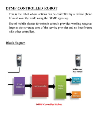
  • 1. DTMF CONTROLLED ROBOT This is the robot whose actions can be controlled by a mobile phone from all over the world using the DTMF signaling. Use of mobile phones for robotic controls provides working range as large as the coverage area of the service provider and no interference with other controllers. Block diagram DTMF Controlled Robot
  • 2. PROJECT OVERVIEW In this project, the robot is controlled by a mobile phone that makes a call to the mobile phone attached to the robot. In the course of a call, if any button is pressed, a tone corresponding to the button pressed is heard at the other end of the call. This tone is called DTMF (dual-tone- multiple-frequency).The robot perceives this DTMF tone with the help of the phone stacked in the robot. The received tone is processed by the microcontroller residing on the Arduino UNO board with the help of DTMF decoder IC (MT8870). The decoder decodes the DTMF tone into its equivalent binary digit and this binary number is sent to the microcontroller. The microcontroller is programmed to take a decision for any given input and outputs its decision to motor drivers in order to drive the motors in forward direction or backward direction or turn. The mobile phone that makes a call to mobile phone stacked in the robot act as a remote. DTMF DTMF (Dual tone multi frequency) as the name suggests uses a combination of two sine wave tones to represent a key dialed on a pushbutton or DTMF keypad. These tones are called row and column frequencies as they correspond to the layout of a telephone keypad.
  • 3. DTMF keypad layout A DTMF keypad (generator or encoder) generates a sinusoidal tone which is mixture of the row and column frequencies. The row and column frequencies corresponding to a DTMF keypad have been indicated in the above figure. DTMF tones are able to represent one of the 16 different states or symbols on the keypad. Hardware components required and their purpose: 1. Arduino UNO board 2. Transmitter and receiver mobile phones 3. DTMF decoder IC (MT8870) 4. DC motor 5. Motor driver IC (L293D) 6. Wheels 7. Power adopter  Arduino UNO board: This is the brain of this robot in which the program is loaded to do the required functioning and is interfaced with decoder IC and the motor driver to make the system work as required.
  • 4.  Transmitter and receiver mobile phones: Here the transmitting phone is working as a remote and the receiving phone is attached to the robot which receives the DTMF signals which are then fed to decoder IC after converting them to electrical form through audio jack.  DTMF decoder IC (MT8870) The decoder decodes the DTMF tone into its equivalent binary digit and this binary number is sent to the microcontroller. DTMF decoder IC (MT8870) On pressing any key say key 1, a combination of frequencies 1209 and 697 Hz will be generated by keypad which is fed to IC through sound converter which in turn produce the output 0001 (Q1, Q2, Q3, Q4). Following table shows output of remaining keys. MT8870 output
  • 5.  DC Motor: This motor is controlled with DC voltages and can move in forward and backward direction according to the polarity of the voltage applied.  Motor driver IC (L293D): Microcontrollers can’t supply the current required by DC motor to run. So, to fulfill this requirement these motor driver ICs are used. DC motors with Driver IC  Power adopter: This is used to give appropriate dc power supply to microcontroller, driver IC sensors and the other passive components of the robot.  Wheels: In it three wheels are employed, two at rear end and one at front end. Rear wheels are attached with the motors and also control the steering of robot. Front wheel is the loose steered wheel which moves in the direction of the pressure applied to it.
  • 6. Overview: Top view of robot Description The robot is controlled by a mobile phone that makes call to the mobile phone attached to the robot and in the course of the call, if any button is pressed the corresponding DTMF freq. will be heard at the other end. DTMF assigns a specific frequency (consisting of two separate tones) to each key that it can easily be identified by the electronic circuit. The signal generated by the DTMF encoder is the direct algebraic submission, in real time of the amplitudes of two sine(cosine) waves of different frequencies, for example: pressing key5 will send a tone made by adding 1336hz and 770hz to the other end of the mobile.
  • 7. The received tone is processed by the atmega8 microcontroller with the help of DTMF decoder (MT8870). The decoder decodes the DTMF tone in to its equivalent binary digit and this binary number is send to the microcontroller. The microcontroller is preprogrammed to take a decision for any given input and outputs its decision to motor drivers in order to drive the motors for forward or backward motion or a turn. Program: /*DTMF pins Q1-4 are attached with pins 9-12 left motor attached to pin 5,6 and right motor attached to pin 7,8 and */ int q1=9; int q2=10; int q3=11; int q4=12; void setup() { //Initialize serial and wait for port to open: Serial.begin(9600); pinMode(q1, INPUT); pinMode(q2, INPUT); pinMode(q3, INPUT); pinMode(q4, INPUT); pinMode(5, OUTPUT); pinMode(6, OUTPUT);
  • 8. pinMode(7, OUTPUT); pinMode(8, OUTPUT); } void loop() { int v1,v2,v3,v4,value; v1 = digitalRead(q1); v2 = digitalRead(q2); v3 = digitalRead(q3); v4 = digitalRead(q4); value=((v4<<3)|(v3<<2)|(v2<<1)|(v1)); switch(value) { case 0X02: { digitalWrite(6, LOW); digitalWrite(8, LOW); digitalWrite(5, HIGH); digitalWrite(7, HIGH); //switch on both break; } case 6: //RIGHT turn { digitalWrite(5, HIGH); digitalWrite(7, LOW); digitalWrite(6, LOW); digitalWrite(8, LOW); //switch on only LEFT motor move to RIGHT break; }
  • 9. case 4: //LEFT turn { digitalWrite(5, LOW); digitalWrite(7, HIGH); digitalWrite(6, LOW); digitalWrite(8, LOW); //switch on only RIGHT motor move to LEFT break; } case 8: { digitalWrite(5, LOW); digitalWrite(7, LOW); digitalWrite(6, HIGH); digitalWrite(8, HIGH); //both REVERSE break; } default: { digitalWrite(5, LOW); digitalWrite(7, LOW); digitalWrite(6, LOW); digitalWrite(8, LOW); break; } } }
  • 10. Programming Digital I/O pins of Arduino UNO board:  Each pin is controlled by three commands associated with it which are designated as: pinMode() digitalWrite() digitalRead()  pinMode() This configures the specified pin to behave either as an input or an output. Syntax pinMode(pin, mode) Parameters pin: the number of the pin whose mode you wish to set mode: INPUT, OUTPUT. Returns None Example int ledPin = 13; // LED connected to digital pin 13 void setup() { pinMode(ledPin, OUTPUT); // sets the digital pin as output } void loop() { digitalWrite(ledPin, HIGH); // sets the LED on delay(1000); // waits for a second digitalWrite(ledPin, LOW); // sets the LED off delay(1000); // waits for a second }
  • 11.  digitalWrite() Write a HIGH or a LOW value to a digital pin. If the pin has been configured as an OUTPUT with pinMode(), its voltage will be set to the corresponding value: 5V (or 3.3V on 3.3V boards) for HIGH, 0V (ground) for LOW. Syntax digitalWrite(pin, value) Parameters pin: the pin number value: HIGH or LOW Returns None Example Sets pin 13 to HIGH, makes a one-second-long delay, and sets the pin back to LOW. int ledPin = 13; // LED connected to digital pin 13 void setup() { pinMode(ledPin, OUTPUT); // sets the digital pin as output } void loop() { digitalWrite(ledPin, HIGH); // sets the LED on delay(1000); // waits for a second digitalWrite(ledPin, LOW); // sets the LED off delay(1000); // waits for a second }
  • 12.  digitalRead() Reads the value from a specified digital pin, either HIGH or LOW. Syntax digitalRead(pin) Parameters pin: the number of the digital pin you want to read (int) Returns HIGH or LOW Example int ledPin = 13; // LED connected to digital pin 13 int inPin = 7; // pushbutton connected to digital pin 7 int val = 0; // variable to store the read value void setup() { pinMode(ledPin, OUTPUT); // sets the digital pin 13 as output pinMode(inPin, INPUT); // sets the digital pin 7 as input } void loop() { val = digitalRead(inPin); // read the input pin digitalWrite(ledPin, val); // sets the LED to the button's value }