SlideShare a Scribd company logo
1 of 1
Download to read offline
INTERSERVE DEFENCE LIMITED
DISCRETE WORKS TEAM
STRUCTURAL & CIVIL ENGINEERING PROJECTS
SEISMIC ASSESSMENT OF REINFORCED CONCRETE
WATER TOWER - MT0580
SEISMIC ASSESSMENT OF UNREINFORCED MASONRY
STRUCTURE - EP0022
DESIGN OF PV ARRAY IN EPISKOPI GARRISON
KENSINGTON VILLAGE
DESIGN OF VARIOUS OBSERVATION TOWERS IN
RAF AKROTIRI & DHEKELIA PYLA RANGE
STRUCTURAL DESIGN REVIEW OF THE STEEL CANOPY
STRUCTURE AT DHEKELIA STATION
LIVE LOAD ASSESSMENT OF NORMANDY BRIDGE
IN DHEKELIA STATION
STRUCTURAL ASSESSMENT OF 16m FLOODLIGHT
COLUMN IN DHEKELIA STATION
ASBESTOS REMOVAL FROM VARIOUS SFA ISLAND-WIDE
DESCRIPTION OF THE PROJECT
Name of project: Seismic Assessment of Reinforced concrete water tower
Location: Dhekelia Station
Usage of the structure: Water tower
Structural Engineer: Valentinos Neophytou
Scope of project: Seismic assessment
Level of seismic action used: 0.05g-0.15g
Type of analysis used: Dynamic Modal Response Spectrum Analysis.
Size of structure: 20m high
Figure 1: Structural model Figure 2: Mode shape 1 (T=0.418s) - Translation Y dir. Figure 3: Mode shape 2 (T=0.418s) - Translation X dir. Figure 4: Mode shape 3 (T=0.212s) - Torsional
Figure 6: Maximum base shear for EQX load case Figure 7: Maximum displacement for EQX load case Figure 8: Maximum overturning moment for EQX load case
DESCRIPTION OF THE STRUCTURE
The structure comprises 2 N0. GRP sectional water storage tanks with plan
dimensions 8.0m x 4.0m. The tanks which store potable water are supported by a
concrete support tower of reinforced concrete construction, 4.4 square on plan,
with a height of 19m from top of foundation to top of the tower. The reinforced
concrete walls of the support tower are 400mm thick and the splayed top of the
tower onto which the No tanks are supported measures 12.9m square on plan.
The foundation of the tower is of a concrete construction with dimensions 12m x
12m on plan by 1.2m deep.
Structural stability of the concrete tower is obtained from the interaction of the
reinforced concrete walls, roof and foundation. Transfer of forces and moments
between different elements of the tower is by means of moment connections
formed by the steel reinforcement within the concrete.
DESCRIPTION OF THE PROJECT
Name of project: Seismic Assessment of Uneinforced masonry structure
Location: Episkopi Garrison
Usage of the structure: Telephone exchange facility
Structural Engineer: Valentinos Neophytou
Scope of project: Seismic assessment
Level of seismic action used: 0.05g
Type of analysis used: Dynamic Modal Response Spectrum Analysis.
Size of structure: W:8xL:20m
DESCRIPTION OF THE STRUCTURE
The building is a single storey rectangular structure which is regular in plan and
elevation. The overall dimensions are 8.2m x 20.4m. The height to the eaves is
3.1m and 5.7m to the roof ridge, above the ground floor slab. The walls are
founded to sit on strip footings, approximately 500mm below existing ground
level.
There is no rigid slab in the building, therefore flexible diaphragm behavior has
been assumed in the mathematical model.
The concrete masonry hollow section is filled by concrete, as identify in the
drawings and laboratory test. Walls support a series of steel framed trusses (No.
5 - see drawings at Annex A) with timber purlins and rafters with conventional
clay tiled roof. The ceiling is formed by metal lathe and plaster construction. At
roof level, all the walls are connected by continuous RC ring beams. All the RC
ring beams have a width equal to the wall thickness. The ring beams are
reinforced with three 12mm rebars. The RC ring beams of the buildings have a
depth of 30 cm.
Figure 1: Structural model
Figure 3: In plane shear force (SMAX) - North Elevation Figure 4: In plane shear force (SMAX) - South Elevation
Figure 7: In plane shear force (F12) - East Elevation Figure 8: In plane shear force (F12) - West Elevation
Figure 2: Out of plane bending perpendicular to the horizontal bed joints (M22)
Figure 6: Out of plane bending perpendicular to the horizontal bed joints (M22)Figure 5: Photos of strucutre
Figure 5: Photo of structure
DESCRIPTION OF THE PROJECT
Name of project: Design of PV solar array
Location: Episkopi Garrison
Usage of the structure: Photovoltaic system
Structural Engineer: M&I Constantinou
Scope of project: Design of PV solar array
Level of seismic action used: 0.25g
Type of analysis used: Lateral force method of analysis.
Size of structure: 2310m2
Figure 1: Structural model Figure 2: Maximum overturning moment at base
TREE TO BE TRIMMED
TREE TO BE REMOVED/
RELOCATED
AREA REQUIRED FOR PV INSTALLATION
ELECTRICAL SUBSTATION
(EP0053 & EP053A)
LOCATION OF ELECTRICAL
(LV) CABLE
GOOGLE MAPS
2
AREA:2310m
Figure 4: Aerial view of the proposed location
1.55
3.47
3.21
0.95
0.60
1.30
1.66
1.66
1.55
3.47
3.21
0.95
0.60
1.30
1.66
1.66
7.50
15mm GAP BETWEEN
MODULES IN ALL DIRECTION
3.47
0.43
PV MODULES IN PORTRAIT
ORIENTATION
PEAK POWER OF EACH
MODULE IS 250W
TYPICAL BEAM AND COLUMN SUPPORTS
MEMBERS. ALL SIZES OF STRUCTURAL
COMPONENTS TO BE
SPECIFIED BY THE MANUFACTURER
SIDE VIEW OF PV ARRAY
SCALE 1:25
FRONT VIEW OF PV ARRAY
SCALE 1:25
MODULES DIMENSIONS
1665X991X38mm
MODULES DIMENSIONS
1665X991X38mm
4.74
0.10
BLINDING CONCRETE
100mm
GRAVEL LAYER
100mm
BLINDING CONCRETE
100mm
GRAVEL LAYER
100mm
0.10
GEOTEXTILE LAYER
1mm THICK
1200g POLYTHENE MEMBRANE
GEOTEXTILE LAYER
1mm THICK
1200g POLYTHENE MEMBRANE
7.14
0.99 0.99 0.99 0.99 0.99 0.99 0.99
7.14
0.99 0.99 0.99 0.99 0.99 0.99 0.99
0.30
Figure 3: Maximum base shear at base
DESCRIPTION OF THE STRUCTURE
The project scope includes the installation of 99KVA Pilot
Photo-Voltaic (PV) Solar Array in Kensington village.
The proposed project is a renewable energy generation
facility which will utilize solar photovoltaic technology to
generate electricity. The installation consists of a standalone
PV solar array 1-way fixed. When operating this PV system
will generate electricity in parallel with the local utility service
provider.
The project consists six raw of PV array and the project area
required is of approximately 2310m2.
Figure 5: Solar Photovoltaic system structure (Front view) Figure 6: Solar Photovoltaic system structure (Back view)
47.06
ROW 1
ROW 2
ROW 3
ROW 4
ROW 5
ROW 6
ARRAY 4
(14PV MODULES)
ARRAY 5
(14PV MODULES)
ARRAY 1
(12PV MODULES)
ARRAY 2
(12PV MODULES)
ARRAY 3
(14PV MODULES)
ARRAY 4
(14PV MODULES)
ARRAY 5
(14PV MODULES)
ARRAY 1
(12PV MODULES)
ARRAY 2
(12PV MODULES)
ARRAY 3
(14PV MODULES)
ARRAY 4
(14PV MODULES)
ARRAY 5
(14PV MODULES)
ARRAY 1
(12PV MODULES)
ARRAY 2
(12PV MODULES)
ARRAY 3
(14PV MODULES)
ARRAY 4
(14PV MODULES)
ARRAY 5
(14PV MODULES)
ARRAY 1
(12PV MODULES)
ARRAY 2
(12PV MODULES)
ARRAY 3
(14PV MODULES)
ARRAY 4
(14PV MODULES)
ARRAY 5
(14PV MODULES)
ARRAY 1
(12PV MODULES)
ARRAY 2
(12PV MODULES)
ARRAY 3
(14PV MODULES)
ARRAY 4
(14PV MODULES)
ARRAY 5
(14PV MODULES)
10.1310.1310.1310.1310.13
54.68
ARRAY 1
(12PV MODULES)
ARRAY 2
(12PV MODULES)
ARRAY 2
(14PV MODULES)
GB2-1 GB2-2 GB2-3 GB2-4 GB2-5
GB3-1 GB3-2 GB3-3 GB3-4 GB3-5
GB4-1 GB4-2 GB4-3 GB4-4 GB4-5
GB5-1 GB5-2 GB5-3 GB5-4 GB5-5
GB6-1 GB6-2 GB6-3 GB6-4 GB6-5
GB2-1 GB2-2 GB2-3 GB2-4 GB2-5
0.430.430.430.43
7.00
2.902.90
7.00
2.902.90
OM NLJ K
7.00
2.902.90
IG H
2.402.40
6.00
FD E
2.402.40
6.00
CA B
LAYOUT OF PV ARRAY
FOUNDATION BEAM
H:600mm x W:1300mm
LAYOUT OF PV ARRAY
FOUNDATION BEAM
H:600mm x W:1300mm
LAYOUT OF PV ARRAY
FOUNDATION BEAM
H:600mm x W:1300mm
LAYOUT OF PV ARRAY
FOUNDATION BEAM
H:600mm x W:1300mm
LAYOUT OF PV ARRAY
FOUNDATION BEAM
H:600mm x W:1300mm
LAYOUT OF PV ARRAY
FOUNDATION BEAM
H:600mm x W:1300mm
LAYOUT OF PV ARRAY
FOUNDATION BEAM
H:600mm x W:1300mm
SECTION VIEW (FOUNDATION BEAM) - A-A
SCALE 1:10
PART OF FOUNDATION PLAN (SINGLE GROUND BEAM)
SCALE 1:25
SCHEDULE OF GROUND BEAMS
BOTTOM
REINFORCEMENT
TOP BOTTOM
SIZENo
1300X300GB6-5
GB1-5 1300X600
GB5-5
GB3-5
GB4-4
1300X600
1300X600
1300X600
1300X600GB2-5
7Y167Y16
ZONE B
Y10/200
LINKS
7Y167Y16
7Y167Y16
7Y167Y16
7Y167Y16
7Y167Y16
Y10/200
Y10/200
Y10/200
Y10/200
Y10/200
SECTION VIEW (FOUNDATION BEAM) - B-B
SCALE 1:25
LONGITUDINAL
REINFORCEMENT
TO BE BEND 90deg
AND TO BE EXTENDED
400mm VERTICALLY
LONGITUDINAL REINFORCEMENT
TO BE BEND 90deg AND TO BE
EXTENDED 400mm VERTICALLY
600mm
BLINDING CONCRETE C16/20
HEIGHT:100mm
1200g POLYTHENE MEMBRANE
7000mm
F.G.L.
STEEL COLUMNSTEEL COLUMN
2 LINKS
1001
576
GEOTEXTILE 1mm THICK
GRAVEL LAYER (SEE DRAWING14023-GD4)
HEIGHT:100mm
SUBSTANDARD SOIL BASE STRUCTURAL DETAIL OF INVERTED BASE
SCALE 1:10
MESH #A142
A A
SUBSTANDARD SOIL BASE
1200g POLYTHENE MEMBRANE
GEOTEXTILE 1mm THICK
GRAVEL LAYER (SEE DRAWING14023-GD4)
HEIGHT:100mm
1.17
0.59
0.17
SECTION A-A
ALL BOLTS TO BE CAST WITH
CONCRETE AT FULL DEPTH
OF FOUNDATION BEAM
SUBSTANDARD SOIL BASE
600mm
FOUNDATION BEAM TOP
LONGITUDINAL REINFORCEMENT
7Y16
FOUNDATION BEAM BOTTOM
LONGITUDINAL REINFORCEMENT
7Y16
FOUNDATION BEAM
REINFORCEMENT
STIRRUPS (TIES)
Y8-200
1300mm
F.G.L.
1200g POLYTHENE MEMBRANE
GEOTEXTILE 1mm THICK
GRAVEL LAYER (SEE
DRAWING14023-GD4)
HEIGHT:100mm
FOUNDATION BEAM BOTTOM
TRANSVERSE REINFORCEMENT
Y16-200
FOUNDATION BEAM BOTTOM
TRANSVERSE REINFORCEMENT
Y16-200
FOUNDATION BEAM
REINFORCEMENT
STIRRUPS (TIES)
Y8-200
FOUNDATION BEAM
REINFORCEMENT
STIRRUPS (TIES)
Y8-200
1.40 1.99 1.40 1.99 1.40
STEEL COLUMNSTEEL COLUMNSTEEL COLUMN
1.52
B B
A
A
ALL BOLTS TO BE CAST WITH
CONCRETE AT FULL DEPTH
OF FOUNDATION BEAM
TRANSVERSELONGITUDINALLONGITUDINAL
Y16/200
Y16/200
Y16/200
Y16/200
Y16/200
Y16/200
Figure 7: Side and front Elevation views of PV array Figure 8: Plan view of PV array Figure 9: Plan view of concrete footing of PV array Figure 10: Structural detail of concrete footing
DESCRIPTION OF THE PROJECT
Name of project: Design of four Observation towers
Location: RAF Akrotiri & Dhekelia Pyla Range
Usage of the structure: Observation tower
Structural Engineer: Valentinos Neophytou
Scope of project: Design of steel tower
Level of seismic action used: 0.25g
Type of analysis used: Dynamic Modal Response Spectrum Analysis.
Size of structure: 6m & 12m high
SECTION B-B
SCALE: 1:50
SECTION A-A
SCALE: 1:50
SECTION A'-A'
SCALE: 1:50
SECTION B-B
SCALE: 1:50
BALLISTIC PROTECTION
PARAPET
(SEE DRAWING
14180-SD1 FOR DETAILS)
BALLISTIC PROTECTION
PARAPET
(SEE DRAWING
14180-SD1 FOR DETAILS)
NEW RC SLAB, SLAB
DEPTH 300mm
EXISTING CONCRETE
FOUNDATION
EXISTING
GROUND
LEVEL
NEW RC SLAB, SLAB
DEPTH 300mm
EXISTING CONCRETE
FOUNDATION
EXISTING
GROUND
LEVEL
EXISTING CONCRETE
FOUNDATION
EXISTING
GROUND
LEVEL
EXISTING CONCRETE
FOUNDATION
100mm THICK
CRUSHER RUN
100mm THICK
OF BLINDING
CONCRETE
L70X70X6
L70X70X6
L70X70X6
L70X70X6
HEB200
HEB200
HEB200
IPE200
IPE200
HEB200
HEB200
HEB200
IPE200
IPE200
IPE200
OPEN STEEL
GALVANIZED ANTI-SLIP
FLOOR. SIZE OF
FLOOR IS
800X242mm.BAR
DIMENSIONS 25X5mm
ANTI SLIP OPEN GALVANISED STEEL
RECTANGULAR GRATING BY LIONWELD LTD
REPRESENTED IN CYPRUS BY STYLSON
ENGINE.CO LTD OR EQUIVALENT.
MESH SIZE 25X3 "SAFELOCK DOUBLE
SERRATED - TYPE N SYSTEM".
L70X70X6
L70X70X6
L70X70X6
L70X70X6
HEB200
HEB200
HEB200
IPE200
IPE200
HEB200
HEB200
HEB200
IPE200
IPE200
IPE200
298928622672
298928622672
1200 GAUGE
POLYTHENE
SHEET
100mm THICK
CRUSHER RUN
100mm THICK
OF BLINDING
CONCRETE
1200 GAUGE
POLYTHENE
SHEET
DETAIL 7
(see drawing
14180-SD3)
DETAIL 8
(see drawing
14180-SD3)
8523
VERIFY THAT THE EXISTING CONCRETE
BASE HAS A MINIMUM DEPTH OF 300mm.
IF THE DEPTH IS LESS THAN 300mm,
INCREASE THE DEPTH OF THE NEW SLAB
BY 200mm AND LAY 16mm STEEL
REINFORCEMENT INSTEAD OF 12mm.
VERIFY THAT THE EXISTING CONCRETE
BASE HAS A MINIMUM DEPTH OF 300mm.
IF THE DEPTH IS LESS THAN 300mm,
INCREASE THE DEPTH OF THE NEW SLAB
BY 200mm AND LAY 16mm STEEL
REINFORCEMENT INSTEAD OF 12mm.
5450
775 3200 1475
4750
775 3200 775
APPLY BITUMEN
MATERIAL AROUND
THE SIDE OF THE
FOUNDATION
APPLY BITUMEN
MATERIAL AROUND
THE SIDE OF THE
FOUNDATION
APPLY BITUMEN
MATERIAL AROUND
THE SIDE OF THE
FOUNDATION
UPN200
RO33.7X2.6RO33.7X2.6RO33.7X2.6
RO42.4X4
OPEN STEEL
GALVANIZED ANTI-SLIP
FLOOR. SIZE OF
FLOOR IS
800X250mm.BAR
DIMENSIONS 25X5mm
IPE200
HEB200
HEB200
IPE200
IPE240
IPE200
UPN200
L70X70X6
L70X70X6
BALLISTIC PROTECTION
PARAPET
(SEE DRAWING
14180-SD1 FOR DETAILS)
IPE200
HEB200 HEB200
IPE200
IPE200
UPN200
UPN200
EXISTING
GROUND
LEVEL
NEW RC SLAB
5000X5000X200mm
EXISTING CONCRETE
FOUNDATION
0.20m
2.99m2.56m
NEW RC SLAB
5000X5000X200mm
EXISTING CONCRETE
FOUNDATION
EXISTING GROUND LEVEL
0.20m2.99m2.56m
3.20m0.90m
NEW RC
FOUNDATION FOR
STAIRCASE
(1200X900X300mm)
BACKFILL
FORM
EXISTING
GROUND
100mm
CRUSHER RUN
1200 GAUGE
POLYTHENE
SHEET
IPE200
5.75m
5.75m
DETAIL 7
(see drawing
14180-SD3)
DETAIL 8
(see drawing
14180-SD3)
L70X70X6
L70X70X6
DETAIL 7
(see drawing
14180-SD3)
DETAIL 8
(see drawing
14180-SD3)
BALLISTIC PROTECTION
PARAPET
(SEE DRAWING
14180-SD1 FOR DETAILS)
SEE DRAWING 14180-SD1
FOR CONSTRUCTION
DETAILS
1.20m 2.60m 1.20m 1.20m 2.60m 1.20m
Figure 2: Structural model - MT0502 Figure 3: Structural model - MT0501, MT0560 & MT0561
Figure 4: Structural design to Eurocode 3
A
D
2
IPE160
IPE160
IPE160
IPE200
IPE200
IPE140
IPE140
IPE140
IPE140
IPE140
IPE140
IPE200IPE200
IPE200IPE200
IPE140
IPE140
IPE140
IPE200
IPE200
IPE140
IPE140
IPE140
IPE240
IPE240
UPN200
UPN200
UPN200
UPN200
FIRST FLOOR PLAN (PLATFORM)
SCALE: 1:50
FOUNDATION PLAN VIEW
SCALE: 1:50
ROOF PLAN
SCALE: 1:50
IPE160
IPE160
IPE160
IPE200
IPE200
IPE200
IPE200
UPN200
UPN200
1
21
A
D
A
D
1 2
3
B
C
AA
B'
B'
Y12-200
Y12-200
1
d=200
Y12-200
Y12-200
B
B
A'A'
d=300
2
Y10-200
Y10-200
DETAIL 6
(see drawing
14180-SD3)
DETAIL 4
(see drawing
14180-SD2)
DETAIL 3
(see drawing
14180-SD2)
DETAIL 1
(see drawing
14180-SD2)
2.60m
1.27m1.27m
1.27m2.60m1.27m
2.60m1.20m 1.20m
1.20m1.20m
8.65m
5.00m
2.60m
2.60m
2.60m
HEB200
PLT 340X340X25
HEB200
PLT 340X340X25
HEB200
PLT 340X340X25
HEB200
PLT 340X340X25
OPEN STEEL GALVANIZED
ANTI-SLIP FLOOR. SIZE OF FLOOR
IS 800X250mm.BAR
DIMENSIONS 25X5mm. SEE DETAIL
11 IN DRAWING 14180-SD4.
0.90m
1.20m
NEW REINFORCED
CONCRETE FOUNDATION
FOR STAIRCASE
(1200X900X300mm)
STEEL BASE PLATE
CONNECTION OF UPN200
TO NEW CONCRETE
FOUNDATION
PLT 330X85X10
3.65m
0.87m
0.87m
0.86m
NEW REINFORCED
CONCRETE (RC) TO BE CAST
ON EXISTING CONCRETE
FOUNDATION
SLAB 5000X5000X200mm.
SEE DETAIL 10 IN DRAWING
14180-SD4
5.15m
5.15m
DETAIL 2
(see drawing
14180-SD2)
ALL UPN200 STEEL SECTIONS OF THE FLOOR
PLAN (PERIMETER BEAMS)
ARE TO BE CUT IN 45deg AND ARE TO
WELDED TOGETHER.
1150
1140
564
568
DETAIL 5
(see drawing
14180-SD3)
SIKAFLOO-PROSEAL OR
EQUIVALENT TO BE APPLIED
ON ALL CONCRETE
SURFACE.
SIKAFLOO-PROSEAL OR
EQUIVALENT TO BE APPLIED
ON ALL CONCRETE
SURFACE.
Figure 5: Maximum displacement Figure 6: Mode shape 1 - T=0.219s Figure 7: Mode shape 2 - T=0.163s Figure 8: Axial force diagram Figure 9: Shear force diagram Figure 10: Bending moment diagram
Figure 1: Existing Tower MT0502 (West & South Elevation views)
Figure 11: Structural drawings - Plans (MT0501,MT0560 & MT0561) Figure 12: Structural drawings - Elevations (MT0502) Figure 13: Structural drawings - Elevations (MT0501)
DESCRIPTION OF THE PROJECT
Name of project: Structural design review of steel canopy roof
Location: Dhekelia Station
Usage of the structure: Canopy roof
Structural Engineer: Valentinos Neophytou
Scope of project: Design engineering review of steel canopy roof
Level of seismic action used: 0.25g
Type of analysis used: Dynamic Modal Response Spectrum Analysis.
Size of structure: 9.1m & 7m
Figure 1: Structural model Figure 2: Bending moment diagram
Figure 3: Various photographs during construction of steel open canopy roof structure
DESCRIPTION OF THE PROJECT
Name of project: Assessment of live load carrying capacity
Location: Dhekelia Station
Usage of the structure: Bridge
Structural Engineer: Valentinos Neophytou
Scope of project: Assessment of live load carrying capacity
Level of seismic action used: N/A
Type of analysis used: Static & Moving load analysis.
Size of structure: 60m long in total (5 spans)
Figure 2: Load case 2: Loaded span 1-5
Figure 4: Load case 2: Loaded span 1
Figure 6: Load case 3: Loaded span 3
Figure 8: Load case 4: Loaded span 2
Figure 1: Structural model
Figure 3: Deformation shape of load case 2
Figure 5: Deformation shape of load case 2
Figure 7: Deformation shape of load case 3
Figure 9: Deformation shape of load case 4
DESCRIPTION OF THE PROJECT
Name of project: STRUCTURAL ASSESSMENT OF FLOODLIGHT
COLUMNS
Location: Dhekelia Station
Usage of the structure: Floodlight
Structural Engineer: Valentinos Neophytou
Scope of project: Structural assessment
Level of seismic action used: 0.25g
Type of analysis used: Linear static analysis
Size of structure: 16m high
DESCRIPTION OF THE STRUCTURE
The structures are octagonal steel columns sections with a height
of 16m.
One of the 6 floodlight column was picked for analysis as all
floodlight column are identically. The top of the steel column
supports rectangular steel beam (head-frame) where 4 floodlights
are attached. One single obstruction light and air terminator single
rod is also attached on the top of the column.
All columns are hinged at base and are raised and lowered by the
use of jack frame assembly. The hinge base plate is made of
hot-dip galvanised and bolted on foundation base plate connection.
The access point for lowering and rising the column using jack
frame assembly has been closed by welding steel plate sections.
The structure acts as a freestanding cantilever, where the tube is
transferring vertical and lateral loads to the foundation. Lateral
stability in all direction is provided by the moment connection of the
steel structure to the foundation.
Figure 2: Structural modelFigure 1: Floodlight column Figure 3: Bending moment diagram Figure 4: Shear force diagram
Figure 7: Structural/general details of the structure
Figure 5: Maximum displacement
under wind loading
Figure 6: Structural calculations
DESCRIPTION OF THE PROJECT
Name of project: Asbestos removale from various SFA island-wide
Location: RAF Akrotiri, Episkopi & Dhekelia
Usage of the structure: Service family accommodation
Structural Engineer: Valentinos Neophytou
Scope of project: Design of reinstatement works following asbestos
removal
Level of seismic action used: N/A
Type of analysis used: N/A
Size of structure: 236 buildings
DESCRIPTION OF THE STRUCTURE
The project is related to various assets located at the WSBA and
ESBA Sites and which are listed in Annex A-C of this specification
(sorted per site). Each of the assets, contain various asbestos
containing materials, which have been identified by Asbestos
Management Surveys carried out in the past.
The project involves carrying out asbestos removals works by the
Licensed Asbestos Specialist Contractor undertaking the project.
Remove and dispose as contaminated waste of the external asbestos
soffit boards of the building. The works require being undertaken
partial enclosure where the asbestos material is not crysotile.
Remove and dispose as contaminated waste of the external asbestos
gutters/downpipes of the building. The works require being
undertaken partial enclosure where the asbestos material is not
crysotile.
MT0015
MT0020
MT0016
MT0017
42
41
40
39
29
30
31
32
37 38
35 36
28 27
26 25 24
23 22
21
20
19
18 17
16 15
3433
2
1
3
45
14 15 16
4
5
6
1
2
3
6
7 81
2
3
4
5
10
11
12
13
14
9
6 8
10
12
2
4
3
1
7
5
6
8
PHILIP ROAD
11
9
86
57
3 1
911
2 4
171
D113
DUKESTREET
3 1
MIUN3
MIL2
42
LANIA ROCK CHAMBERS
SITE PLAN AT RAF AKROTIRI INDICATING "AREA 1" AND "AREA 2" WHERE WORK IS TO BE CARRIED OUT
SCALE: NOT TO SCALE
TO SERVICE FAMILIES ACCOMMODATION (SFA)
LEGEND
SFA "TYPE B" REQUIRING
ASBESTOS REMOVAL AND
NON-ASBESTOS REINSTATEMENT WORK
SFA "TYPE C" REQUIRING
ASBESTOS REMOVAL AND
NON-ASBESTOS REINSTATEMENT
WORK
SITE PLAN AT EPISKOPI - KENSIGTON VILLAGE INDICATING WHERE WORK IS TO BE CARRIED OUT
SCALE: NOT TO SCALE
TO SERVICE FAMILIES ACCOMMODATION (SFA)
LEGEND
SFA "TYPE C/V-A & V-A" REQUIRING
ASBESTOS REMOVAL AND NON-ASBESTOS
REINSTATEMENT WORK
SFA "TYPE V-B & C/V-B" REQUIRING
ASBESTOS REMOVAL AND NON-ASBESTOS
REINSTATEMENT WORK
SFA "TYPE IV-B" REQUIRING ASBESTOS
REMOVAL AND NON-ASBESTOS
REINSTATEMENT WORK
SFA "TYPE IV-A" REQUIRING ASBESTOS
REMOVAL AND NON-ASBESTOS
REINSTATEMENT WORK
REMOVE EXISTING
TIMBER FASCIA BOARDS.
PROVIDE NEW 250X30mm
THICK FASCIA BOARDS AND
TO BE PAINTED AS PER
SECTION G.1 OF
THE SPECIFICATION -PART 2
REMOVE EXISTING ASBESTOS
CEMENT SOFFIT BOARDS
AS PER SPECIFICATION.
PROVIDE 12mm THICK
CEMENT BOARD "MAGNUM BOARD"
OR EQUAL APPROVED
WITH 30mins FIRE RATING.
FIX TO EXISTING SUPPORTS.
EXISTING UPVC GUTTER
AND DOWN PIPES. PROVIDE
NEW 150mm UPVC GUTTERS
AND 100mm UPVC DOWNPIPES.
REMOVE EXISTING
TIMBER FASCIA BOARDS.
PROVIDE NEW 250X30mm
THICK FASCIA BOARDS AND
TO BE PAINTED AS PER
SECTION G.1 OF
THE SPECIFICATION -PART 2
REMOVE EXISTING ASBESTOS
CEMENT SOFFIT BOARDS
AS PER SPECIFICATION.
PROVIDE 12mm THICK
CEMENT BOARD "MAGNUM BOARD"
OR EQUAL APPROVED
WITH 30mins FIRE RATING.
FIX TO EXISTING SUPPORTS.
ROOF PLAN - SFA "TYPE C"
SCALE 1:50
BUILDING 1 BUILDING 2
DETAIL-C
SEE DRAWING
14162-AD1
DETAIL-C
SEE DRAWING
14162-AD1
DETAIL-C
SEE DRAWING
14162-AD1
DETAIL-B
SEE DRAWING
14162-AD1
DETAIL-B
SEE DRAWING
14162-AD1
DETAIL-B
SEE DRAWING
14162-AD1
DETAIL-A
SEE DRAWING
14162-AD1
DETAIL-A
SEE DRAWING
14162-AD1
DETAIL-C
SEE DRAWING
14162-AD1
DETAIL-C
SEE DRAWING
14162-AD1
DETAIL-C
SEE DRAWING
14162-AD1
REMOVE EXISTING
TIMBER FASCIA BOARDS.
PROVIDE NEW 250X30mm
THICK FASCIA BOARDS AND
TO BE PAINTED AS PER
SECTION G.1 OF
THE SPECIFICATION -PART 2
REMOVE EXISTING ASBESTOS
CEMENT SOFFIT BOARDS
AS PER SPECIFICATION.
PROVIDE 12mm THICK
CEMENT BOARD "MAGNUM BOARD"
OR EQUAL APPROVED
WITH 30mins FIRE RATING.
FIX TO EXISTING SUPPORTS.
EXISTING UPVC GUTTER
AND DOWN PIPES. PROVIDE
NEW 150mm UPVC GUTTERS
AND 100mm UPVC DOWNPIPES.
REMOVE EXISTING ASBESTOS
CEMENT SOFFIT BOARDS
AS PER SPECIFICATION.
PROVIDE 12mm THICK
CEMENT BOARD "MAGNUM BOARD"
OR EQUAL APPROVED
WITH 30mins FIRE RATING.
FIX TO EXISTING SUPPORTS.
DETAIL-B
SEE DRAWING
14162-AD1
DETAIL-B
SEE DRAWING
14162-AD1
DETAIL-A
SEE DRAWING
14162-AD1
DETAIL-A
SEE DRAWING
14162-AD1
DETAIL-B
SEE DRAWING
14162-AD1
REMOVE EXISTING
TIMBER FASCIA BOARDS.
PROVIDE NEW 250X30mm
THICK FASCIA BOARDS AND
TO BE PAINTED AS PER
SECTION G.1 OF
THE SPECIFICATION -PART 2
FRONT ELEVATION - SFA "TYPE C"
SCALE 1:50
SIDE ELEVATION - SFA "TYPE C"
SCALE 1:50
BACK ELEVATION - SFA "TYPE C"
SCALE 1:50
SIDE ELEVATION - SFA "TYPE C"
SCALE 1:50
REMOVE EXISTING
TIMBER EAVE BOARDS.
PROVIDE NEW 250X30mm
THICK EAVE BOARDS AND
TO BE PAINTED AS PER
SECTION G.1 OF
THE SPECIFICATION-
PART 2. MAKE GOOD ALL
DISTURB AREA (I.E. ROOF
CLAY TILES).
REMOVE EXISTING
TIMBER EAVE BOARDS.
PROVIDE NEW 250X30mm
THICK EAVE BOARDS AND
TO BE PAINTED AS PER
SECTION G.1 OF
THE SPECIFICATION-
PART 2. MAKE GOOD ALL
DISTURB AREA (I.E. ROOF
CLAY TILES).
EXISTING TIMBER
CLADDING TO BE
PAINTED AS PER SECTION
G.1 OF THE SPECIFICATION
REMOVE EXISTING
TIMBER FASCIA BOARDS.
PROVIDE NEW 250X30mm
THICK FASCIA BOARDS AND
TO BE PAINTED AS PER
SECTION G.1 OF
THE SPECIFICATION -PART 2
REMOVE EXISTING ASBESTOS
CEMENT SOFFIT BOARDS
AS PER SPECIFICATION.
PROVIDE 12mm THICK
CEMENT BOARD "MAGNUM BOARD"
OR EQUAL APPROVED.
FIX TO EXISTING SUPPORTS.
EXISTING UPVC GUTTER
AND DOWN PIPES. PROVIDE
NEW 150mm UPVC GUTTERS
AND 100mm UPVC DOWNPIPES.
EXISTING UPVC GUTTER
AND DOWN PIPES. PROVIDE
NEW 150mm UPVC GUTTERS
AND 100mm UPVC DOWNPIPES.
REMOVE EXISTING ASBESTOS
CEMENT SOFFIT BOARDS
AS PER SPECIFICATION.
PROVIDE 12mm THICK
CEMENT BOARD "MAGNUM BOARD"
OR EQUAL APPROVED.
FIX TO EXISTING SUPPORTS.
REMOVE EXISTING
TIMBER FASCIA BOARDS.
PROVIDE NEW 250X30mm
THICK FASCIA BOARDS AND
TO BE PAINTED AS PER
SECTION G.1 OF
THE SPECIFICATION -PART 2
REMOVE EXISTING ASBESTOS
CEMENT SOFFIT BOARDS
AS PER SPECIFICATION.
PROVIDE 12mm THICK
CEMENT BOARD "MAGNUM BOARD"
OR EQUAL APPROVED
WITH 30mins FIRE RATING.
FIX TO EXISTING SUPPORTS.
EXISTING UPVC GUTTER
AND DOWN PIPES. PROVIDE
NEW 150mm UPVC GUTTERS
AND 100mm UPVC DOWNPIPES.
EXISTING UPVC GUTTER
AND DOWN PIPES. PROVIDE
NEW 150mm UPVC GUTTERS
AND 100mm UPVC DOWNPIPES.
REMOVE EXISTING ASBESTOS
CEMENT SOFFIT BOARDS
AS PER SPECIFICATION.
PROVIDE 12mm THICK
CEMENT BOARD "MAGNUM BOARD"
OR EQUAL APPROVED
WITH 30mins FIRE RATING.
FIX TO EXISTING SUPPORTS.
EXISTING TIMBER
CLADDING TO BE
PAINTED AS PER SECTION
G.1 OF THE SPECIFICATION
Figure 1: Site plan at RAF Akrotiri indicating the location where asbestos removal is to be carried out Figure 2: Site plan at Episkopi indicating the location where asbestos removal is to be carried out
Figure 3: Plan view of SFA "Type C" - RAF Akrotiri Figure 3: Elevation view of SFA "Type C" - RAF Akrotiri

More Related Content

What's hot

Study on Effect of Wind Load and Earthquake Load on Multi-storey RC Framed Bu...
Study on Effect of Wind Load and Earthquake Load on Multi-storey RC Framed Bu...Study on Effect of Wind Load and Earthquake Load on Multi-storey RC Framed Bu...
Study on Effect of Wind Load and Earthquake Load on Multi-storey RC Framed Bu...
IJSRD
 

What's hot (20)

IRJET- Comparative Analysis of Seismic Behavior of Flat Slab and Conventional...
IRJET- Comparative Analysis of Seismic Behavior of Flat Slab and Conventional...IRJET- Comparative Analysis of Seismic Behavior of Flat Slab and Conventional...
IRJET- Comparative Analysis of Seismic Behavior of Flat Slab and Conventional...
 
Design and analasys of a g+3 residential building using staad
Design and analasys of a g+3 residential building using staadDesign and analasys of a g+3 residential building using staad
Design and analasys of a g+3 residential building using staad
 
IRJET- Comparative Study of Seismic Analysis of Multi Storied Building with a...
IRJET- Comparative Study of Seismic Analysis of Multi Storied Building with a...IRJET- Comparative Study of Seismic Analysis of Multi Storied Building with a...
IRJET- Comparative Study of Seismic Analysis of Multi Storied Building with a...
 
A Comperative study of Analysis of a G+3 Residential Building by the Equivale...
A Comperative study of Analysis of a G+3 Residential Building by the Equivale...A Comperative study of Analysis of a G+3 Residential Building by the Equivale...
A Comperative study of Analysis of a G+3 Residential Building by the Equivale...
 
Design of residential building
Design of residential buildingDesign of residential building
Design of residential building
 
Analysis and Design of Earthquake Resistant RC multi storied (G+3) Residentia...
Analysis and Design of Earthquake Resistant RC multi storied (G+3) Residentia...Analysis and Design of Earthquake Resistant RC multi storied (G+3) Residentia...
Analysis and Design of Earthquake Resistant RC multi storied (G+3) Residentia...
 
An analysis of multi-storey building with floating and non-floating column un...
An analysis of multi-storey building with floating and non-floating column un...An analysis of multi-storey building with floating and non-floating column un...
An analysis of multi-storey building with floating and non-floating column un...
 
Study on Effect of Wind Load and Earthquake Load on Multi-storey RC Framed Bu...
Study on Effect of Wind Load and Earthquake Load on Multi-storey RC Framed Bu...Study on Effect of Wind Load and Earthquake Load on Multi-storey RC Framed Bu...
Study on Effect of Wind Load and Earthquake Load on Multi-storey RC Framed Bu...
 
Robustezza Strutturale
Robustezza StrutturaleRobustezza Strutturale
Robustezza Strutturale
 
Seismic Drift Control in soft storied RCC buildings
Seismic Drift Control in soft storied RCC buildingsSeismic Drift Control in soft storied RCC buildings
Seismic Drift Control in soft storied RCC buildings
 
ANALYSIS & DESIGN OF G+3 STORIED REINFORCED CONCRETE BUILDING
ANALYSIS & DESIGN OF G+3 STORIED REINFORCED CONCRETE BUILDING ANALYSIS & DESIGN OF G+3 STORIED REINFORCED CONCRETE BUILDING
ANALYSIS & DESIGN OF G+3 STORIED REINFORCED CONCRETE BUILDING
 
Dynamic Analysis of Multistorey framed structure with roof tower
Dynamic Analysis of Multistorey framed structure with roof towerDynamic Analysis of Multistorey framed structure with roof tower
Dynamic Analysis of Multistorey framed structure with roof tower
 
Analysis and design of high rise building frame using staad pro
Analysis and design of high rise building frame using staad proAnalysis and design of high rise building frame using staad pro
Analysis and design of high rise building frame using staad pro
 
IRJET- Structural Analysis and Design of Pump House
IRJET- Structural Analysis and Design of Pump HouseIRJET- Structural Analysis and Design of Pump House
IRJET- Structural Analysis and Design of Pump House
 
DESIGN OF G+20 MULTISTOREY BUILDING
DESIGN OF G+20 MULTISTOREY BUILDINGDESIGN OF G+20 MULTISTOREY BUILDING
DESIGN OF G+20 MULTISTOREY BUILDING
 
Economic Concrete Frame Elements to Eurocode 2
Economic Concrete Frame Elements to Eurocode 2Economic Concrete Frame Elements to Eurocode 2
Economic Concrete Frame Elements to Eurocode 2
 
Design of housing apartment
Design of  housing apartmentDesign of  housing apartment
Design of housing apartment
 
residential buliding by stadd pro
residential buliding by stadd proresidential buliding by stadd pro
residential buliding by stadd pro
 
Design & Analysis of G+2 Residential Building Using STAAD Pro
Design & Analysis of G+2 Residential Building Using STAAD ProDesign & Analysis of G+2 Residential Building Using STAAD Pro
Design & Analysis of G+2 Residential Building Using STAAD Pro
 
Peb 1234330943765774 1
Peb 1234330943765774 1Peb 1234330943765774 1
Peb 1234330943765774 1
 

Viewers also liked

Membrane - Plate - Shell
Membrane - Plate - ShellMembrane - Plate - Shell
Membrane - Plate - Shell
neikrof
 
Design.guide.post tensioned.concrete.floors-cps
Design.guide.post tensioned.concrete.floors-cpsDesign.guide.post tensioned.concrete.floors-cps
Design.guide.post tensioned.concrete.floors-cps
Luan Truong Van
 
The project of steel building with 3D model
The project of steel building with 3D modelThe project of steel building with 3D model
The project of steel building with 3D model
Jovan Kostic
 

Viewers also liked (20)

Simplified notes of calculate Wind & Snow loads based on CYS EC1
Simplified notes of calculate Wind & Snow loads based on CYS EC1Simplified notes of calculate Wind & Snow loads based on CYS EC1
Simplified notes of calculate Wind & Snow loads based on CYS EC1
 
STRUCTURAL DESIGN OF PIPE CULVERT TO BS EN 1295-1
STRUCTURAL DESIGN OF PIPE CULVERT TO BS EN 1295-1STRUCTURAL DESIGN OF PIPE CULVERT TO BS EN 1295-1
STRUCTURAL DESIGN OF PIPE CULVERT TO BS EN 1295-1
 
CSI ETABS & SAFE MANUAL: Slab Analysis and Design to EC2
CSI ETABS & SAFE MANUAL: Slab Analysis and Design to EC2CSI ETABS & SAFE MANUAL: Slab Analysis and Design to EC2
CSI ETABS & SAFE MANUAL: Slab Analysis and Design to EC2
 
Wind load on pv system
Wind load on pv systemWind load on pv system
Wind load on pv system
 
Seismic assessment of buildings accordance to Eurocode 8 Part 3
Seismic assessment of buildings accordance to Eurocode 8 Part 3Seismic assessment of buildings accordance to Eurocode 8 Part 3
Seismic assessment of buildings accordance to Eurocode 8 Part 3
 
ETABS Modelling
ETABS ModellingETABS Modelling
ETABS Modelling
 
Etabs modelling parameters
Etabs modelling parametersEtabs modelling parameters
Etabs modelling parameters
 
Design notes for seismic design of building accordance to Eurocode 8
Design notes for seismic design of building accordance to Eurocode 8 Design notes for seismic design of building accordance to Eurocode 8
Design notes for seismic design of building accordance to Eurocode 8
 
Etabs modeling - Design of slab according to EC2
Etabs modeling  - Design of slab according to EC2Etabs modeling  - Design of slab according to EC2
Etabs modeling - Design of slab according to EC2
 
ETABS manual - Seismic design of steel buildings according to Eurocode 3 & 8
ETABS manual - Seismic design of steel buildings according to Eurocode 3 & 8 ETABS manual - Seismic design of steel buildings according to Eurocode 3 & 8
ETABS manual - Seismic design of steel buildings according to Eurocode 3 & 8
 
WIND LOADING ON LIGHTING STEEL COLUMN - EN 40-3-1:2013
WIND LOADING ON LIGHTING STEEL COLUMN - EN 40-3-1:2013WIND LOADING ON LIGHTING STEEL COLUMN - EN 40-3-1:2013
WIND LOADING ON LIGHTING STEEL COLUMN - EN 40-3-1:2013
 
Loadings snow - wind
Loadings   snow - windLoadings   snow - wind
Loadings snow - wind
 
Membrane - Plate - Shell
Membrane - Plate - ShellMembrane - Plate - Shell
Membrane - Plate - Shell
 
THEORY 1 : V & M diagrams
THEORY 1 : V & M diagramsTHEORY 1 : V & M diagrams
THEORY 1 : V & M diagrams
 
Rubblization
RubblizationRubblization
Rubblization
 
Wri 03 forcesstaticfluids
Wri 03 forcesstaticfluidsWri 03 forcesstaticfluids
Wri 03 forcesstaticfluids
 
Lecture earthquake-2
Lecture earthquake-2Lecture earthquake-2
Lecture earthquake-2
 
Design.guide.post tensioned.concrete.floors-cps
Design.guide.post tensioned.concrete.floors-cpsDesign.guide.post tensioned.concrete.floors-cps
Design.guide.post tensioned.concrete.floors-cps
 
The project of steel building with 3D model
The project of steel building with 3D modelThe project of steel building with 3D model
The project of steel building with 3D model
 
HANS STEEL CANADA 3D-1 MODEL
HANS STEEL CANADA 3D-1 MODELHANS STEEL CANADA 3D-1 MODEL
HANS STEEL CANADA 3D-1 MODEL
 

Similar to PORTFOLIO-Model

Structural Behaviors of Reinforced Concrete Dome with Shell System under Vari...
Structural Behaviors of Reinforced Concrete Dome with Shell System under Vari...Structural Behaviors of Reinforced Concrete Dome with Shell System under Vari...
Structural Behaviors of Reinforced Concrete Dome with Shell System under Vari...
ijtsrd
 
Rion antirion - yerevan - oct 2003
Rion antirion - yerevan  - oct 2003Rion antirion - yerevan  - oct 2003
Rion antirion - yerevan - oct 2003
gefyra-rion
 
Arch.CE Portfolio
Arch.CE PortfolioArch.CE Portfolio
Arch.CE Portfolio
Angela Su
 

Similar to PORTFOLIO-Model (20)

IRJET- A Study on Seismic Analysis of RC Framed Structures on Varying Slo...
IRJET-  	  A Study on Seismic Analysis of RC Framed Structures on Varying Slo...IRJET-  	  A Study on Seismic Analysis of RC Framed Structures on Varying Slo...
IRJET- A Study on Seismic Analysis of RC Framed Structures on Varying Slo...
 
Leisure Center. Part 2
Leisure Center. Part 2Leisure Center. Part 2
Leisure Center. Part 2
 
Fip rion2
Fip rion2Fip rion2
Fip rion2
 
The optimum location of shear wall in high rise r.c bulidings under lateral l...
The optimum location of shear wall in high rise r.c bulidings under lateral l...The optimum location of shear wall in high rise r.c bulidings under lateral l...
The optimum location of shear wall in high rise r.c bulidings under lateral l...
 
IRJET- A Research on Comparing the Effect of Seismic Waves on Multistoried Bu...
IRJET- A Research on Comparing the Effect of Seismic Waves on Multistoried Bu...IRJET- A Research on Comparing the Effect of Seismic Waves on Multistoried Bu...
IRJET- A Research on Comparing the Effect of Seismic Waves on Multistoried Bu...
 
IRJET- A Study on Seismic Evaluation of RC Framed Structures on Varying Perce...
IRJET- A Study on Seismic Evaluation of RC Framed Structures on Varying Perce...IRJET- A Study on Seismic Evaluation of RC Framed Structures on Varying Perce...
IRJET- A Study on Seismic Evaluation of RC Framed Structures on Varying Perce...
 
Structural Behaviors of Reinforced Concrete Dome with Shell System under Vari...
Structural Behaviors of Reinforced Concrete Dome with Shell System under Vari...Structural Behaviors of Reinforced Concrete Dome with Shell System under Vari...
Structural Behaviors of Reinforced Concrete Dome with Shell System under Vari...
 
Seismic response of steel beams coupling concrete walls
Seismic response of steel beams coupling concrete wallsSeismic response of steel beams coupling concrete walls
Seismic response of steel beams coupling concrete walls
 
Seismic Performance and Shear Wall Position Assessment of the Buildings Resti...
Seismic Performance and Shear Wall Position Assessment of the Buildings Resti...Seismic Performance and Shear Wall Position Assessment of the Buildings Resti...
Seismic Performance and Shear Wall Position Assessment of the Buildings Resti...
 
“THE SEISMIC RESISTANCE OF THE DIFFERENT INFILL MATERIALS USED IN THE CONSTRU...
“THE SEISMIC RESISTANCE OF THE DIFFERENT INFILL MATERIALS USED IN THE CONSTRU...“THE SEISMIC RESISTANCE OF THE DIFFERENT INFILL MATERIALS USED IN THE CONSTRU...
“THE SEISMIC RESISTANCE OF THE DIFFERENT INFILL MATERIALS USED IN THE CONSTRU...
 
“THE SEISMIC RESISTANCE OF THE DIFFERENT INFILL MATERIALS USED IN THE CONSTRU...
“THE SEISMIC RESISTANCE OF THE DIFFERENT INFILL MATERIALS USED IN THE CONSTRU...“THE SEISMIC RESISTANCE OF THE DIFFERENT INFILL MATERIALS USED IN THE CONSTRU...
“THE SEISMIC RESISTANCE OF THE DIFFERENT INFILL MATERIALS USED IN THE CONSTRU...
 
Evaluation of Seismic Behaviour of RCC Building using Coupled Shear wall
Evaluation of Seismic Behaviour of RCC Building using Coupled Shear wallEvaluation of Seismic Behaviour of RCC Building using Coupled Shear wall
Evaluation of Seismic Behaviour of RCC Building using Coupled Shear wall
 
IRJET- Comparative Study of Usage of Outrigger and B-ELT Truss System for Hig...
IRJET- Comparative Study of Usage of Outrigger and B-ELT Truss System for Hig...IRJET- Comparative Study of Usage of Outrigger and B-ELT Truss System for Hig...
IRJET- Comparative Study of Usage of Outrigger and B-ELT Truss System for Hig...
 
Tokyo Sky Tree
Tokyo Sky TreeTokyo Sky Tree
Tokyo Sky Tree
 
Inelastic seismic response of single-story structure in hilly areas owing to ...
Inelastic seismic response of single-story structure in hilly areas owing to ...Inelastic seismic response of single-story structure in hilly areas owing to ...
Inelastic seismic response of single-story structure in hilly areas owing to ...
 
IRJET- Performance Evaluation of Friction Damper for Steel Structure
IRJET-  	  Performance Evaluation of Friction Damper for Steel StructureIRJET-  	  Performance Evaluation of Friction Damper for Steel Structure
IRJET- Performance Evaluation of Friction Damper for Steel Structure
 
Rion antirion - yerevan - oct 2003
Rion antirion - yerevan  - oct 2003Rion antirion - yerevan  - oct 2003
Rion antirion - yerevan - oct 2003
 
Arch.CE Portfolio
Arch.CE PortfolioArch.CE Portfolio
Arch.CE Portfolio
 
IRJET - Study on Lateral Structural System on Different Height on Asymmet...
IRJET -  	  Study on Lateral Structural System on Different Height on Asymmet...IRJET -  	  Study on Lateral Structural System on Different Height on Asymmet...
IRJET - Study on Lateral Structural System on Different Height on Asymmet...
 
Effect of Positioning and Configuration of Shear Walls on Seismic Performance...
Effect of Positioning and Configuration of Shear Walls on Seismic Performance...Effect of Positioning and Configuration of Shear Walls on Seismic Performance...
Effect of Positioning and Configuration of Shear Walls on Seismic Performance...
 

PORTFOLIO-Model

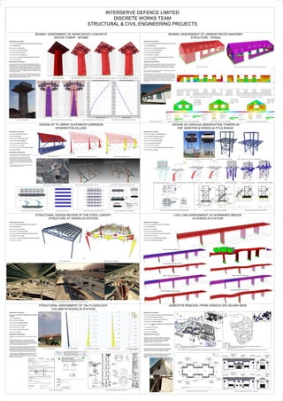
  • 1. INTERSERVE DEFENCE LIMITED DISCRETE WORKS TEAM STRUCTURAL & CIVIL ENGINEERING PROJECTS SEISMIC ASSESSMENT OF REINFORCED CONCRETE WATER TOWER - MT0580 SEISMIC ASSESSMENT OF UNREINFORCED MASONRY STRUCTURE - EP0022 DESIGN OF PV ARRAY IN EPISKOPI GARRISON KENSINGTON VILLAGE DESIGN OF VARIOUS OBSERVATION TOWERS IN RAF AKROTIRI & DHEKELIA PYLA RANGE STRUCTURAL DESIGN REVIEW OF THE STEEL CANOPY STRUCTURE AT DHEKELIA STATION LIVE LOAD ASSESSMENT OF NORMANDY BRIDGE IN DHEKELIA STATION STRUCTURAL ASSESSMENT OF 16m FLOODLIGHT COLUMN IN DHEKELIA STATION ASBESTOS REMOVAL FROM VARIOUS SFA ISLAND-WIDE DESCRIPTION OF THE PROJECT Name of project: Seismic Assessment of Reinforced concrete water tower Location: Dhekelia Station Usage of the structure: Water tower Structural Engineer: Valentinos Neophytou Scope of project: Seismic assessment Level of seismic action used: 0.05g-0.15g Type of analysis used: Dynamic Modal Response Spectrum Analysis. Size of structure: 20m high Figure 1: Structural model Figure 2: Mode shape 1 (T=0.418s) - Translation Y dir. Figure 3: Mode shape 2 (T=0.418s) - Translation X dir. Figure 4: Mode shape 3 (T=0.212s) - Torsional Figure 6: Maximum base shear for EQX load case Figure 7: Maximum displacement for EQX load case Figure 8: Maximum overturning moment for EQX load case DESCRIPTION OF THE STRUCTURE The structure comprises 2 N0. GRP sectional water storage tanks with plan dimensions 8.0m x 4.0m. The tanks which store potable water are supported by a concrete support tower of reinforced concrete construction, 4.4 square on plan, with a height of 19m from top of foundation to top of the tower. The reinforced concrete walls of the support tower are 400mm thick and the splayed top of the tower onto which the No tanks are supported measures 12.9m square on plan. The foundation of the tower is of a concrete construction with dimensions 12m x 12m on plan by 1.2m deep. Structural stability of the concrete tower is obtained from the interaction of the reinforced concrete walls, roof and foundation. Transfer of forces and moments between different elements of the tower is by means of moment connections formed by the steel reinforcement within the concrete. DESCRIPTION OF THE PROJECT Name of project: Seismic Assessment of Uneinforced masonry structure Location: Episkopi Garrison Usage of the structure: Telephone exchange facility Structural Engineer: Valentinos Neophytou Scope of project: Seismic assessment Level of seismic action used: 0.05g Type of analysis used: Dynamic Modal Response Spectrum Analysis. Size of structure: W:8xL:20m DESCRIPTION OF THE STRUCTURE The building is a single storey rectangular structure which is regular in plan and elevation. The overall dimensions are 8.2m x 20.4m. The height to the eaves is 3.1m and 5.7m to the roof ridge, above the ground floor slab. The walls are founded to sit on strip footings, approximately 500mm below existing ground level. There is no rigid slab in the building, therefore flexible diaphragm behavior has been assumed in the mathematical model. The concrete masonry hollow section is filled by concrete, as identify in the drawings and laboratory test. Walls support a series of steel framed trusses (No. 5 - see drawings at Annex A) with timber purlins and rafters with conventional clay tiled roof. The ceiling is formed by metal lathe and plaster construction. At roof level, all the walls are connected by continuous RC ring beams. All the RC ring beams have a width equal to the wall thickness. The ring beams are reinforced with three 12mm rebars. The RC ring beams of the buildings have a depth of 30 cm. Figure 1: Structural model Figure 3: In plane shear force (SMAX) - North Elevation Figure 4: In plane shear force (SMAX) - South Elevation Figure 7: In plane shear force (F12) - East Elevation Figure 8: In plane shear force (F12) - West Elevation Figure 2: Out of plane bending perpendicular to the horizontal bed joints (M22) Figure 6: Out of plane bending perpendicular to the horizontal bed joints (M22)Figure 5: Photos of strucutre Figure 5: Photo of structure DESCRIPTION OF THE PROJECT Name of project: Design of PV solar array Location: Episkopi Garrison Usage of the structure: Photovoltaic system Structural Engineer: M&I Constantinou Scope of project: Design of PV solar array Level of seismic action used: 0.25g Type of analysis used: Lateral force method of analysis. Size of structure: 2310m2 Figure 1: Structural model Figure 2: Maximum overturning moment at base TREE TO BE TRIMMED TREE TO BE REMOVED/ RELOCATED AREA REQUIRED FOR PV INSTALLATION ELECTRICAL SUBSTATION (EP0053 & EP053A) LOCATION OF ELECTRICAL (LV) CABLE GOOGLE MAPS 2 AREA:2310m Figure 4: Aerial view of the proposed location 1.55 3.47 3.21 0.95 0.60 1.30 1.66 1.66 1.55 3.47 3.21 0.95 0.60 1.30 1.66 1.66 7.50 15mm GAP BETWEEN MODULES IN ALL DIRECTION 3.47 0.43 PV MODULES IN PORTRAIT ORIENTATION PEAK POWER OF EACH MODULE IS 250W TYPICAL BEAM AND COLUMN SUPPORTS MEMBERS. ALL SIZES OF STRUCTURAL COMPONENTS TO BE SPECIFIED BY THE MANUFACTURER SIDE VIEW OF PV ARRAY SCALE 1:25 FRONT VIEW OF PV ARRAY SCALE 1:25 MODULES DIMENSIONS 1665X991X38mm MODULES DIMENSIONS 1665X991X38mm 4.74 0.10 BLINDING CONCRETE 100mm GRAVEL LAYER 100mm BLINDING CONCRETE 100mm GRAVEL LAYER 100mm 0.10 GEOTEXTILE LAYER 1mm THICK 1200g POLYTHENE MEMBRANE GEOTEXTILE LAYER 1mm THICK 1200g POLYTHENE MEMBRANE 7.14 0.99 0.99 0.99 0.99 0.99 0.99 0.99 7.14 0.99 0.99 0.99 0.99 0.99 0.99 0.99 0.30 Figure 3: Maximum base shear at base DESCRIPTION OF THE STRUCTURE The project scope includes the installation of 99KVA Pilot Photo-Voltaic (PV) Solar Array in Kensington village. The proposed project is a renewable energy generation facility which will utilize solar photovoltaic technology to generate electricity. The installation consists of a standalone PV solar array 1-way fixed. When operating this PV system will generate electricity in parallel with the local utility service provider. The project consists six raw of PV array and the project area required is of approximately 2310m2. Figure 5: Solar Photovoltaic system structure (Front view) Figure 6: Solar Photovoltaic system structure (Back view) 47.06 ROW 1 ROW 2 ROW 3 ROW 4 ROW 5 ROW 6 ARRAY 4 (14PV MODULES) ARRAY 5 (14PV MODULES) ARRAY 1 (12PV MODULES) ARRAY 2 (12PV MODULES) ARRAY 3 (14PV MODULES) ARRAY 4 (14PV MODULES) ARRAY 5 (14PV MODULES) ARRAY 1 (12PV MODULES) ARRAY 2 (12PV MODULES) ARRAY 3 (14PV MODULES) ARRAY 4 (14PV MODULES) ARRAY 5 (14PV MODULES) ARRAY 1 (12PV MODULES) ARRAY 2 (12PV MODULES) ARRAY 3 (14PV MODULES) ARRAY 4 (14PV MODULES) ARRAY 5 (14PV MODULES) ARRAY 1 (12PV MODULES) ARRAY 2 (12PV MODULES) ARRAY 3 (14PV MODULES) ARRAY 4 (14PV MODULES) ARRAY 5 (14PV MODULES) ARRAY 1 (12PV MODULES) ARRAY 2 (12PV MODULES) ARRAY 3 (14PV MODULES) ARRAY 4 (14PV MODULES) ARRAY 5 (14PV MODULES) 10.1310.1310.1310.1310.13 54.68 ARRAY 1 (12PV MODULES) ARRAY 2 (12PV MODULES) ARRAY 2 (14PV MODULES) GB2-1 GB2-2 GB2-3 GB2-4 GB2-5 GB3-1 GB3-2 GB3-3 GB3-4 GB3-5 GB4-1 GB4-2 GB4-3 GB4-4 GB4-5 GB5-1 GB5-2 GB5-3 GB5-4 GB5-5 GB6-1 GB6-2 GB6-3 GB6-4 GB6-5 GB2-1 GB2-2 GB2-3 GB2-4 GB2-5 0.430.430.430.43 7.00 2.902.90 7.00 2.902.90 OM NLJ K 7.00 2.902.90 IG H 2.402.40 6.00 FD E 2.402.40 6.00 CA B LAYOUT OF PV ARRAY FOUNDATION BEAM H:600mm x W:1300mm LAYOUT OF PV ARRAY FOUNDATION BEAM H:600mm x W:1300mm LAYOUT OF PV ARRAY FOUNDATION BEAM H:600mm x W:1300mm LAYOUT OF PV ARRAY FOUNDATION BEAM H:600mm x W:1300mm LAYOUT OF PV ARRAY FOUNDATION BEAM H:600mm x W:1300mm LAYOUT OF PV ARRAY FOUNDATION BEAM H:600mm x W:1300mm LAYOUT OF PV ARRAY FOUNDATION BEAM H:600mm x W:1300mm SECTION VIEW (FOUNDATION BEAM) - A-A SCALE 1:10 PART OF FOUNDATION PLAN (SINGLE GROUND BEAM) SCALE 1:25 SCHEDULE OF GROUND BEAMS BOTTOM REINFORCEMENT TOP BOTTOM SIZENo 1300X300GB6-5 GB1-5 1300X600 GB5-5 GB3-5 GB4-4 1300X600 1300X600 1300X600 1300X600GB2-5 7Y167Y16 ZONE B Y10/200 LINKS 7Y167Y16 7Y167Y16 7Y167Y16 7Y167Y16 7Y167Y16 Y10/200 Y10/200 Y10/200 Y10/200 Y10/200 SECTION VIEW (FOUNDATION BEAM) - B-B SCALE 1:25 LONGITUDINAL REINFORCEMENT TO BE BEND 90deg AND TO BE EXTENDED 400mm VERTICALLY LONGITUDINAL REINFORCEMENT TO BE BEND 90deg AND TO BE EXTENDED 400mm VERTICALLY 600mm BLINDING CONCRETE C16/20 HEIGHT:100mm 1200g POLYTHENE MEMBRANE 7000mm F.G.L. STEEL COLUMNSTEEL COLUMN 2 LINKS 1001 576 GEOTEXTILE 1mm THICK GRAVEL LAYER (SEE DRAWING14023-GD4) HEIGHT:100mm SUBSTANDARD SOIL BASE STRUCTURAL DETAIL OF INVERTED BASE SCALE 1:10 MESH #A142 A A SUBSTANDARD SOIL BASE 1200g POLYTHENE MEMBRANE GEOTEXTILE 1mm THICK GRAVEL LAYER (SEE DRAWING14023-GD4) HEIGHT:100mm 1.17 0.59 0.17 SECTION A-A ALL BOLTS TO BE CAST WITH CONCRETE AT FULL DEPTH OF FOUNDATION BEAM SUBSTANDARD SOIL BASE 600mm FOUNDATION BEAM TOP LONGITUDINAL REINFORCEMENT 7Y16 FOUNDATION BEAM BOTTOM LONGITUDINAL REINFORCEMENT 7Y16 FOUNDATION BEAM REINFORCEMENT STIRRUPS (TIES) Y8-200 1300mm F.G.L. 1200g POLYTHENE MEMBRANE GEOTEXTILE 1mm THICK GRAVEL LAYER (SEE DRAWING14023-GD4) HEIGHT:100mm FOUNDATION BEAM BOTTOM TRANSVERSE REINFORCEMENT Y16-200 FOUNDATION BEAM BOTTOM TRANSVERSE REINFORCEMENT Y16-200 FOUNDATION BEAM REINFORCEMENT STIRRUPS (TIES) Y8-200 FOUNDATION BEAM REINFORCEMENT STIRRUPS (TIES) Y8-200 1.40 1.99 1.40 1.99 1.40 STEEL COLUMNSTEEL COLUMNSTEEL COLUMN 1.52 B B A A ALL BOLTS TO BE CAST WITH CONCRETE AT FULL DEPTH OF FOUNDATION BEAM TRANSVERSELONGITUDINALLONGITUDINAL Y16/200 Y16/200 Y16/200 Y16/200 Y16/200 Y16/200 Figure 7: Side and front Elevation views of PV array Figure 8: Plan view of PV array Figure 9: Plan view of concrete footing of PV array Figure 10: Structural detail of concrete footing DESCRIPTION OF THE PROJECT Name of project: Design of four Observation towers Location: RAF Akrotiri & Dhekelia Pyla Range Usage of the structure: Observation tower Structural Engineer: Valentinos Neophytou Scope of project: Design of steel tower Level of seismic action used: 0.25g Type of analysis used: Dynamic Modal Response Spectrum Analysis. Size of structure: 6m & 12m high SECTION B-B SCALE: 1:50 SECTION A-A SCALE: 1:50 SECTION A'-A' SCALE: 1:50 SECTION B-B SCALE: 1:50 BALLISTIC PROTECTION PARAPET (SEE DRAWING 14180-SD1 FOR DETAILS) BALLISTIC PROTECTION PARAPET (SEE DRAWING 14180-SD1 FOR DETAILS) NEW RC SLAB, SLAB DEPTH 300mm EXISTING CONCRETE FOUNDATION EXISTING GROUND LEVEL NEW RC SLAB, SLAB DEPTH 300mm EXISTING CONCRETE FOUNDATION EXISTING GROUND LEVEL EXISTING CONCRETE FOUNDATION EXISTING GROUND LEVEL EXISTING CONCRETE FOUNDATION 100mm THICK CRUSHER RUN 100mm THICK OF BLINDING CONCRETE L70X70X6 L70X70X6 L70X70X6 L70X70X6 HEB200 HEB200 HEB200 IPE200 IPE200 HEB200 HEB200 HEB200 IPE200 IPE200 IPE200 OPEN STEEL GALVANIZED ANTI-SLIP FLOOR. SIZE OF FLOOR IS 800X242mm.BAR DIMENSIONS 25X5mm ANTI SLIP OPEN GALVANISED STEEL RECTANGULAR GRATING BY LIONWELD LTD REPRESENTED IN CYPRUS BY STYLSON ENGINE.CO LTD OR EQUIVALENT. MESH SIZE 25X3 "SAFELOCK DOUBLE SERRATED - TYPE N SYSTEM". L70X70X6 L70X70X6 L70X70X6 L70X70X6 HEB200 HEB200 HEB200 IPE200 IPE200 HEB200 HEB200 HEB200 IPE200 IPE200 IPE200 298928622672 298928622672 1200 GAUGE POLYTHENE SHEET 100mm THICK CRUSHER RUN 100mm THICK OF BLINDING CONCRETE 1200 GAUGE POLYTHENE SHEET DETAIL 7 (see drawing 14180-SD3) DETAIL 8 (see drawing 14180-SD3) 8523 VERIFY THAT THE EXISTING CONCRETE BASE HAS A MINIMUM DEPTH OF 300mm. IF THE DEPTH IS LESS THAN 300mm, INCREASE THE DEPTH OF THE NEW SLAB BY 200mm AND LAY 16mm STEEL REINFORCEMENT INSTEAD OF 12mm. VERIFY THAT THE EXISTING CONCRETE BASE HAS A MINIMUM DEPTH OF 300mm. IF THE DEPTH IS LESS THAN 300mm, INCREASE THE DEPTH OF THE NEW SLAB BY 200mm AND LAY 16mm STEEL REINFORCEMENT INSTEAD OF 12mm. 5450 775 3200 1475 4750 775 3200 775 APPLY BITUMEN MATERIAL AROUND THE SIDE OF THE FOUNDATION APPLY BITUMEN MATERIAL AROUND THE SIDE OF THE FOUNDATION APPLY BITUMEN MATERIAL AROUND THE SIDE OF THE FOUNDATION UPN200 RO33.7X2.6RO33.7X2.6RO33.7X2.6 RO42.4X4 OPEN STEEL GALVANIZED ANTI-SLIP FLOOR. SIZE OF FLOOR IS 800X250mm.BAR DIMENSIONS 25X5mm IPE200 HEB200 HEB200 IPE200 IPE240 IPE200 UPN200 L70X70X6 L70X70X6 BALLISTIC PROTECTION PARAPET (SEE DRAWING 14180-SD1 FOR DETAILS) IPE200 HEB200 HEB200 IPE200 IPE200 UPN200 UPN200 EXISTING GROUND LEVEL NEW RC SLAB 5000X5000X200mm EXISTING CONCRETE FOUNDATION 0.20m 2.99m2.56m NEW RC SLAB 5000X5000X200mm EXISTING CONCRETE FOUNDATION EXISTING GROUND LEVEL 0.20m2.99m2.56m 3.20m0.90m NEW RC FOUNDATION FOR STAIRCASE (1200X900X300mm) BACKFILL FORM EXISTING GROUND 100mm CRUSHER RUN 1200 GAUGE POLYTHENE SHEET IPE200 5.75m 5.75m DETAIL 7 (see drawing 14180-SD3) DETAIL 8 (see drawing 14180-SD3) L70X70X6 L70X70X6 DETAIL 7 (see drawing 14180-SD3) DETAIL 8 (see drawing 14180-SD3) BALLISTIC PROTECTION PARAPET (SEE DRAWING 14180-SD1 FOR DETAILS) SEE DRAWING 14180-SD1 FOR CONSTRUCTION DETAILS 1.20m 2.60m 1.20m 1.20m 2.60m 1.20m Figure 2: Structural model - MT0502 Figure 3: Structural model - MT0501, MT0560 & MT0561 Figure 4: Structural design to Eurocode 3 A D 2 IPE160 IPE160 IPE160 IPE200 IPE200 IPE140 IPE140 IPE140 IPE140 IPE140 IPE140 IPE200IPE200 IPE200IPE200 IPE140 IPE140 IPE140 IPE200 IPE200 IPE140 IPE140 IPE140 IPE240 IPE240 UPN200 UPN200 UPN200 UPN200 FIRST FLOOR PLAN (PLATFORM) SCALE: 1:50 FOUNDATION PLAN VIEW SCALE: 1:50 ROOF PLAN SCALE: 1:50 IPE160 IPE160 IPE160 IPE200 IPE200 IPE200 IPE200 UPN200 UPN200 1 21 A D A D 1 2 3 B C AA B' B' Y12-200 Y12-200 1 d=200 Y12-200 Y12-200 B B A'A' d=300 2 Y10-200 Y10-200 DETAIL 6 (see drawing 14180-SD3) DETAIL 4 (see drawing 14180-SD2) DETAIL 3 (see drawing 14180-SD2) DETAIL 1 (see drawing 14180-SD2) 2.60m 1.27m1.27m 1.27m2.60m1.27m 2.60m1.20m 1.20m 1.20m1.20m 8.65m 5.00m 2.60m 2.60m 2.60m HEB200 PLT 340X340X25 HEB200 PLT 340X340X25 HEB200 PLT 340X340X25 HEB200 PLT 340X340X25 OPEN STEEL GALVANIZED ANTI-SLIP FLOOR. SIZE OF FLOOR IS 800X250mm.BAR DIMENSIONS 25X5mm. SEE DETAIL 11 IN DRAWING 14180-SD4. 0.90m 1.20m NEW REINFORCED CONCRETE FOUNDATION FOR STAIRCASE (1200X900X300mm) STEEL BASE PLATE CONNECTION OF UPN200 TO NEW CONCRETE FOUNDATION PLT 330X85X10 3.65m 0.87m 0.87m 0.86m NEW REINFORCED CONCRETE (RC) TO BE CAST ON EXISTING CONCRETE FOUNDATION SLAB 5000X5000X200mm. SEE DETAIL 10 IN DRAWING 14180-SD4 5.15m 5.15m DETAIL 2 (see drawing 14180-SD2) ALL UPN200 STEEL SECTIONS OF THE FLOOR PLAN (PERIMETER BEAMS) ARE TO BE CUT IN 45deg AND ARE TO WELDED TOGETHER. 1150 1140 564 568 DETAIL 5 (see drawing 14180-SD3) SIKAFLOO-PROSEAL OR EQUIVALENT TO BE APPLIED ON ALL CONCRETE SURFACE. SIKAFLOO-PROSEAL OR EQUIVALENT TO BE APPLIED ON ALL CONCRETE SURFACE. Figure 5: Maximum displacement Figure 6: Mode shape 1 - T=0.219s Figure 7: Mode shape 2 - T=0.163s Figure 8: Axial force diagram Figure 9: Shear force diagram Figure 10: Bending moment diagram Figure 1: Existing Tower MT0502 (West & South Elevation views) Figure 11: Structural drawings - Plans (MT0501,MT0560 & MT0561) Figure 12: Structural drawings - Elevations (MT0502) Figure 13: Structural drawings - Elevations (MT0501) DESCRIPTION OF THE PROJECT Name of project: Structural design review of steel canopy roof Location: Dhekelia Station Usage of the structure: Canopy roof Structural Engineer: Valentinos Neophytou Scope of project: Design engineering review of steel canopy roof Level of seismic action used: 0.25g Type of analysis used: Dynamic Modal Response Spectrum Analysis. Size of structure: 9.1m & 7m Figure 1: Structural model Figure 2: Bending moment diagram Figure 3: Various photographs during construction of steel open canopy roof structure DESCRIPTION OF THE PROJECT Name of project: Assessment of live load carrying capacity Location: Dhekelia Station Usage of the structure: Bridge Structural Engineer: Valentinos Neophytou Scope of project: Assessment of live load carrying capacity Level of seismic action used: N/A Type of analysis used: Static & Moving load analysis. Size of structure: 60m long in total (5 spans) Figure 2: Load case 2: Loaded span 1-5 Figure 4: Load case 2: Loaded span 1 Figure 6: Load case 3: Loaded span 3 Figure 8: Load case 4: Loaded span 2 Figure 1: Structural model Figure 3: Deformation shape of load case 2 Figure 5: Deformation shape of load case 2 Figure 7: Deformation shape of load case 3 Figure 9: Deformation shape of load case 4 DESCRIPTION OF THE PROJECT Name of project: STRUCTURAL ASSESSMENT OF FLOODLIGHT COLUMNS Location: Dhekelia Station Usage of the structure: Floodlight Structural Engineer: Valentinos Neophytou Scope of project: Structural assessment Level of seismic action used: 0.25g Type of analysis used: Linear static analysis Size of structure: 16m high DESCRIPTION OF THE STRUCTURE The structures are octagonal steel columns sections with a height of 16m. One of the 6 floodlight column was picked for analysis as all floodlight column are identically. The top of the steel column supports rectangular steel beam (head-frame) where 4 floodlights are attached. One single obstruction light and air terminator single rod is also attached on the top of the column. All columns are hinged at base and are raised and lowered by the use of jack frame assembly. The hinge base plate is made of hot-dip galvanised and bolted on foundation base plate connection. The access point for lowering and rising the column using jack frame assembly has been closed by welding steel plate sections. The structure acts as a freestanding cantilever, where the tube is transferring vertical and lateral loads to the foundation. Lateral stability in all direction is provided by the moment connection of the steel structure to the foundation. Figure 2: Structural modelFigure 1: Floodlight column Figure 3: Bending moment diagram Figure 4: Shear force diagram Figure 7: Structural/general details of the structure Figure 5: Maximum displacement under wind loading Figure 6: Structural calculations DESCRIPTION OF THE PROJECT Name of project: Asbestos removale from various SFA island-wide Location: RAF Akrotiri, Episkopi & Dhekelia Usage of the structure: Service family accommodation Structural Engineer: Valentinos Neophytou Scope of project: Design of reinstatement works following asbestos removal Level of seismic action used: N/A Type of analysis used: N/A Size of structure: 236 buildings DESCRIPTION OF THE STRUCTURE The project is related to various assets located at the WSBA and ESBA Sites and which are listed in Annex A-C of this specification (sorted per site). Each of the assets, contain various asbestos containing materials, which have been identified by Asbestos Management Surveys carried out in the past. The project involves carrying out asbestos removals works by the Licensed Asbestos Specialist Contractor undertaking the project. Remove and dispose as contaminated waste of the external asbestos soffit boards of the building. The works require being undertaken partial enclosure where the asbestos material is not crysotile. Remove and dispose as contaminated waste of the external asbestos gutters/downpipes of the building. The works require being undertaken partial enclosure where the asbestos material is not crysotile. MT0015 MT0020 MT0016 MT0017 42 41 40 39 29 30 31 32 37 38 35 36 28 27 26 25 24 23 22 21 20 19 18 17 16 15 3433 2 1 3 45 14 15 16 4 5 6 1 2 3 6 7 81 2 3 4 5 10 11 12 13 14 9 6 8 10 12 2 4 3 1 7 5 6 8 PHILIP ROAD 11 9 86 57 3 1 911 2 4 171 D113 DUKESTREET 3 1 MIUN3 MIL2 42 LANIA ROCK CHAMBERS SITE PLAN AT RAF AKROTIRI INDICATING "AREA 1" AND "AREA 2" WHERE WORK IS TO BE CARRIED OUT SCALE: NOT TO SCALE TO SERVICE FAMILIES ACCOMMODATION (SFA) LEGEND SFA "TYPE B" REQUIRING ASBESTOS REMOVAL AND NON-ASBESTOS REINSTATEMENT WORK SFA "TYPE C" REQUIRING ASBESTOS REMOVAL AND NON-ASBESTOS REINSTATEMENT WORK SITE PLAN AT EPISKOPI - KENSIGTON VILLAGE INDICATING WHERE WORK IS TO BE CARRIED OUT SCALE: NOT TO SCALE TO SERVICE FAMILIES ACCOMMODATION (SFA) LEGEND SFA "TYPE C/V-A & V-A" REQUIRING ASBESTOS REMOVAL AND NON-ASBESTOS REINSTATEMENT WORK SFA "TYPE V-B & C/V-B" REQUIRING ASBESTOS REMOVAL AND NON-ASBESTOS REINSTATEMENT WORK SFA "TYPE IV-B" REQUIRING ASBESTOS REMOVAL AND NON-ASBESTOS REINSTATEMENT WORK SFA "TYPE IV-A" REQUIRING ASBESTOS REMOVAL AND NON-ASBESTOS REINSTATEMENT WORK REMOVE EXISTING TIMBER FASCIA BOARDS. PROVIDE NEW 250X30mm THICK FASCIA BOARDS AND TO BE PAINTED AS PER SECTION G.1 OF THE SPECIFICATION -PART 2 REMOVE EXISTING ASBESTOS CEMENT SOFFIT BOARDS AS PER SPECIFICATION. PROVIDE 12mm THICK CEMENT BOARD "MAGNUM BOARD" OR EQUAL APPROVED WITH 30mins FIRE RATING. FIX TO EXISTING SUPPORTS. EXISTING UPVC GUTTER AND DOWN PIPES. PROVIDE NEW 150mm UPVC GUTTERS AND 100mm UPVC DOWNPIPES. REMOVE EXISTING TIMBER FASCIA BOARDS. PROVIDE NEW 250X30mm THICK FASCIA BOARDS AND TO BE PAINTED AS PER SECTION G.1 OF THE SPECIFICATION -PART 2 REMOVE EXISTING ASBESTOS CEMENT SOFFIT BOARDS AS PER SPECIFICATION. PROVIDE 12mm THICK CEMENT BOARD "MAGNUM BOARD" OR EQUAL APPROVED WITH 30mins FIRE RATING. FIX TO EXISTING SUPPORTS. ROOF PLAN - SFA "TYPE C" SCALE 1:50 BUILDING 1 BUILDING 2 DETAIL-C SEE DRAWING 14162-AD1 DETAIL-C SEE DRAWING 14162-AD1 DETAIL-C SEE DRAWING 14162-AD1 DETAIL-B SEE DRAWING 14162-AD1 DETAIL-B SEE DRAWING 14162-AD1 DETAIL-B SEE DRAWING 14162-AD1 DETAIL-A SEE DRAWING 14162-AD1 DETAIL-A SEE DRAWING 14162-AD1 DETAIL-C SEE DRAWING 14162-AD1 DETAIL-C SEE DRAWING 14162-AD1 DETAIL-C SEE DRAWING 14162-AD1 REMOVE EXISTING TIMBER FASCIA BOARDS. PROVIDE NEW 250X30mm THICK FASCIA BOARDS AND TO BE PAINTED AS PER SECTION G.1 OF THE SPECIFICATION -PART 2 REMOVE EXISTING ASBESTOS CEMENT SOFFIT BOARDS AS PER SPECIFICATION. PROVIDE 12mm THICK CEMENT BOARD "MAGNUM BOARD" OR EQUAL APPROVED WITH 30mins FIRE RATING. FIX TO EXISTING SUPPORTS. EXISTING UPVC GUTTER AND DOWN PIPES. PROVIDE NEW 150mm UPVC GUTTERS AND 100mm UPVC DOWNPIPES. REMOVE EXISTING ASBESTOS CEMENT SOFFIT BOARDS AS PER SPECIFICATION. PROVIDE 12mm THICK CEMENT BOARD "MAGNUM BOARD" OR EQUAL APPROVED WITH 30mins FIRE RATING. FIX TO EXISTING SUPPORTS. DETAIL-B SEE DRAWING 14162-AD1 DETAIL-B SEE DRAWING 14162-AD1 DETAIL-A SEE DRAWING 14162-AD1 DETAIL-A SEE DRAWING 14162-AD1 DETAIL-B SEE DRAWING 14162-AD1 REMOVE EXISTING TIMBER FASCIA BOARDS. PROVIDE NEW 250X30mm THICK FASCIA BOARDS AND TO BE PAINTED AS PER SECTION G.1 OF THE SPECIFICATION -PART 2 FRONT ELEVATION - SFA "TYPE C" SCALE 1:50 SIDE ELEVATION - SFA "TYPE C" SCALE 1:50 BACK ELEVATION - SFA "TYPE C" SCALE 1:50 SIDE ELEVATION - SFA "TYPE C" SCALE 1:50 REMOVE EXISTING TIMBER EAVE BOARDS. PROVIDE NEW 250X30mm THICK EAVE BOARDS AND TO BE PAINTED AS PER SECTION G.1 OF THE SPECIFICATION- PART 2. MAKE GOOD ALL DISTURB AREA (I.E. ROOF CLAY TILES). REMOVE EXISTING TIMBER EAVE BOARDS. PROVIDE NEW 250X30mm THICK EAVE BOARDS AND TO BE PAINTED AS PER SECTION G.1 OF THE SPECIFICATION- PART 2. MAKE GOOD ALL DISTURB AREA (I.E. ROOF CLAY TILES). EXISTING TIMBER CLADDING TO BE PAINTED AS PER SECTION G.1 OF THE SPECIFICATION REMOVE EXISTING TIMBER FASCIA BOARDS. PROVIDE NEW 250X30mm THICK FASCIA BOARDS AND TO BE PAINTED AS PER SECTION G.1 OF THE SPECIFICATION -PART 2 REMOVE EXISTING ASBESTOS CEMENT SOFFIT BOARDS AS PER SPECIFICATION. PROVIDE 12mm THICK CEMENT BOARD "MAGNUM BOARD" OR EQUAL APPROVED. FIX TO EXISTING SUPPORTS. EXISTING UPVC GUTTER AND DOWN PIPES. PROVIDE NEW 150mm UPVC GUTTERS AND 100mm UPVC DOWNPIPES. EXISTING UPVC GUTTER AND DOWN PIPES. PROVIDE NEW 150mm UPVC GUTTERS AND 100mm UPVC DOWNPIPES. REMOVE EXISTING ASBESTOS CEMENT SOFFIT BOARDS AS PER SPECIFICATION. PROVIDE 12mm THICK CEMENT BOARD "MAGNUM BOARD" OR EQUAL APPROVED. FIX TO EXISTING SUPPORTS. REMOVE EXISTING TIMBER FASCIA BOARDS. PROVIDE NEW 250X30mm THICK FASCIA BOARDS AND TO BE PAINTED AS PER SECTION G.1 OF THE SPECIFICATION -PART 2 REMOVE EXISTING ASBESTOS CEMENT SOFFIT BOARDS AS PER SPECIFICATION. PROVIDE 12mm THICK CEMENT BOARD "MAGNUM BOARD" OR EQUAL APPROVED WITH 30mins FIRE RATING. FIX TO EXISTING SUPPORTS. EXISTING UPVC GUTTER AND DOWN PIPES. PROVIDE NEW 150mm UPVC GUTTERS AND 100mm UPVC DOWNPIPES. EXISTING UPVC GUTTER AND DOWN PIPES. PROVIDE NEW 150mm UPVC GUTTERS AND 100mm UPVC DOWNPIPES. REMOVE EXISTING ASBESTOS CEMENT SOFFIT BOARDS AS PER SPECIFICATION. PROVIDE 12mm THICK CEMENT BOARD "MAGNUM BOARD" OR EQUAL APPROVED WITH 30mins FIRE RATING. FIX TO EXISTING SUPPORTS. EXISTING TIMBER CLADDING TO BE PAINTED AS PER SECTION G.1 OF THE SPECIFICATION Figure 1: Site plan at RAF Akrotiri indicating the location where asbestos removal is to be carried out Figure 2: Site plan at Episkopi indicating the location where asbestos removal is to be carried out Figure 3: Plan view of SFA "Type C" - RAF Akrotiri Figure 3: Elevation view of SFA "Type C" - RAF Akrotiri