1. 1
MAE 3 Individual Robot Analysis
Archimedes Screw
Robot: Mickey’s Playhouse
Christian Heid (A12851225)
Section A03 Team 33: Mickey’s Playhouse
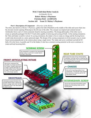
Part 1: Description of Component: (Overview of the Robot)
The robot, also known as Mickey’s Playhouse, gathers the balls (Pokeballs) at the middle of the table and scores them into
the elevated circular opening (Pokestop) at the left-rear of the table. The concept was inspired and centered around
Archimedes Screw and a U-Joint commonly found in steering assemblies. The design philosophy of the robot was to
create an optimally packaged 10x10x17.5-inch robot capable of retrieving and scoring all balls. At the starting orientation,
the Tube and Intake would be vertical. In scoring orientation, the intake is free to rotate at a hinge and the Scoring Screw
would rotate downwards to a static optimized angle. The design of the scoring component revolved around a way to create
linear motion perpendicular to the rotation plane using a single motor. The intake and screw combined can hold all 20
balls (10 in the Screw Assembly and 10 in the Intake). It also has a constant scoring potential as the screw continues to
rotate and load incoming balls.
2. 2
Overview of the Archimedes Screw
The Archimedes screw is made up of 2 parts: The Intermediary Screw (horizontal) and Scoring Screw (angled).
The horizontal Screw is 5.3 inches and transports the balls to the angled scoring Screw which is 15 inches long.
Both Screws are 2.5 inches in width and have an axle diameter of 0.5 inches. The Screw rotates in the counter-
clockwise direction to transfer balls, across in the positive x-axis in relation to the side view of the robot, to the
Scoring Screw, inclined at a 35-degree angle to a specified height of 11 inches in order to reach the highest goal
(5-point goal).
Minimum Set of Functional Requirements (FRs)
Enough torque to overcome binding at the joint and friction of the system and rotate screw
Take at most 10 seconds from intake to score
Collapsible in height
Flexible at joint
Overview of How the Component Functioned
The Archimedes screw performed beyond expectation. The transition from the Intermediary Screw to the Scoring
Screw took some adjusting of the Top Tube Chute Bracket, but once dialed in made the transition flawlessly. The
GM-2 torque motor was enough to overcome the friction between the 3D printed Screw and 3D Printed Tube
Chute. The addition to the Bracket allowing for collapsibility of the screw
in transition from starting orientation to scoring orientation, it also
reduced much of the existing friction because it elevated the screw
above the contact surface. The Screw stows upwards with clearances cut out
in the Tube Chute for retaining walls to pass through, The Scoring
Screw itself rests with high precision on the Intermediary Screw
when upright (Fig. 3). When deployed, the distance between
the two screws maintains its 0.1-inch clearance (Fig. 4).
The only areas of improvement were concluded to be the cycle
time. It averaged 11.2 seconds for time taken from intake to score,
a 12% deviation from our ideal.
Fig. 3
Fig. 4
3. 3
Part 2: Project Management Reflection – Risk Reduction Tests
This reflection will look at the Risk Reduction Test and the things learned from it, which were then
implemented in the final design. The greatest design challenge was the issue of the Scoring Screw being
pulled down by gravity and torsion at the joint, through the string, into the Intermediary Screw. It caused
damage to couplings and broke a couple Screws when the couplings would wrap in on themselves, thus
applying torsional loads they were not mean to withstand and failing as a result. Redesigning the Screw or
Chute was not an option.
The reason this design challenge became such an issue for us was that our risk reduction was done at at
optimal angle for the Screw to function, not to score. Too much creative liberty was taken in making
concept generations work, and did not carry out a Risk Reduction that adequetley addressed aspects of the
design function during compeition. It worked in designing the Screw, but not in the practice of the Screw.
The incline and pitch of the Scoring Screw are much less in Risk Reduction than on the final design. From
the pictures shown, they have the same amount of thread but different spacing. The Risk Reduction Screw
was 8 inches long and weighed 143 grams.
The final design was almost twice the length,
15 inches, weighing 227 grams. The final
design was 87% longer and 60% heavier. The
increased incline combined with the increased
weight added more axial force down into the
joint of the two screws. The problem was that
trying to prop the Screw up using its axle can
work when stationary, but when rotating the
contours of the screw rotate upwards,
interfering with the support.
The solution was the creation of the Tube
Chute Bracket circled in red at the bottom left
of the page. A 10-32 “bolt" was threaded into
the Scoring Screw with a clearance hole in the
Bracket. The progression of the Screw can be
seen in the sequence of images shown below.
The free travel of the bolt seen at the top of
each picture, through the Bracket, lets the
screw fall into position, but stop at a pre-determined distance from the Intermediary
Screw. It supports the weight of the Scoring Screw at the Bracket instead of at the
joint, and eliminates the couplings from wrapping in on themselves.
Original Risk Reduction
Final Design
4. 4
Part 3: Analysis of Component
Objective of Analysis:
The objective of this analysis is to predict the maximum torque needed by the motor to rotate the Screw
Assembly, taking into account factors of the entire system. Calculating the torque required to rotate the
screw can help make design decisions on whether changing 3D printing materials or the orientation during
printing so that the finish on the inside of the screw in smooth. Currently supports were used to print both
the Screws and the Tube Chute. It can also help guide our competition strategy. The concept of the screw
was to store balls while simultaneously scoring them, and having more balls in the system will cause greater
downward force and friction at suspension points.
Free Body Diagram
Front of Intermediary Screw
Side of Screw Assembly
FBD BALL ROTATION
Front of Intermediary Screw
FBD BALL ON SCREW
5. 5
Energy Power Analysis
Assumptions:
o There is no energy loss inside the system, so the heat generated by friction is
negligible.
o The motor accelerates quickly and time required to reach max velocity is
negligible
o Since the Screw is suspended, it acts similar to that when it is completely
horizontal.
Energy Source:
o A GM-2 is the source of rotational force. It is mounted directly into the
Intermediary Screw through an indentation in the Screw. The energy is transferred
through the system by the coupling located at the joint.
GM-2 Max Power: 0.356 W
GM-2 Max Energy in 40 seconds: 0.356 W * 40s = 14.24J
Energy and power required to achieve motion of component:
o The total energy needed to rotate the screw uses the moment of inertia for a solid
cylinder with a mass and radius.
Energy Needed:
Energy Available:
6. 6
Factor of Safety (Energy):
Power Needed:
Factor of Safety (Power):
Force / Torque Analysis
Assumptions:
o The Screw is full with balls
o The Screw is suspended at two points
o Since the Screw is suspended, it acts similar to that when it is completely
horizontal.
o There is a force of friction cause by the ball rotating inside the screw that provides
a resisting force against the motor.
Relevant Equations:
o Friction of Balls:
F btotal ≔F ball1 ⋅ n balls
F ball1 ≔M ball ⋅ g
o Friction of Screw
F screw ≔M screw ⋅ g
o Angular Acceleration:
a ≔(noload/ tchange)
o Torque of Friction:
T friction ≔Ffric ⋅ R
Torque Needed:
7. 7
Torque Required:
Factor of Safety (Torque):
Measurement of Component Performance:
I first relieved the Screw Assembly from the Chute Tube encasement. The Screws could lay flat,
but still elevated above the bottom surface so that there is to friction across the screws. The Tube
Chute Bracket was removed from the Tube Chute as well and served as the stand which elevated
the screw. The entire Screw assembly, including the motor was then removed from the Chassis
and set up as it is in the free body diagram above. I temporarily hot glued the motor mount and
Bracket to two heavy pieces of acrylic to serve as the chassis and Tube Chute. A spring scale
was then attached into a hold that was previously drilled into the end of the Screw axle in order
to act as a entry for a set-screw. The maximum force need to stall the motor can then calculated
utilizing the “holding” feature of the spring scale; it holds the maximum force applied to it with a
small O-ring press fit in the inside of the cylinder.
8. 8
The max force was 30 Newtons.
𝑇𝑚𝑜𝑡𝑜𝑟 𝑚𝑒𝑎𝑠𝑢𝑟𝑒𝑑= (43 N)*( 0.00635m)= 0.27Nm
Now that would mean I was only getting about (0.27Nm/0.34Nm) = 79% of the given stall
torque.
Comparison of analysis to performance and discussion of results:
Using the Theoretic values of the motor that are given:
I am assuming that the distance is the radius of the axle of the motor
Torque = 0.34Nm
o T=F*R
o (0.34Nm)=(F)(.0035m)
o F = 97N
Theoretical Torque:
o T = (97N)(.00635m) = .61Nm
Percent error
o (0.27Nm-0.67Nm)/(0.67Nm) = 60%
As mentioned before the maximum force indicate was used in this experiment. The force spring
scale itself is not the most accurate measuring device either, it has large increments and in not
that accurate. My max force indicator was, the o-ring, was actually a little loose, and I was
measuring the force horizontally. The o-ring may have skipped in its placement I could have
gotten a misread. Theoretically, I should have gotten a larger torque than the given torque
because I was measuring the torque through the axle of the Screw, which was 0.25 inches in
radius whereas the motor only has 0.13 inches.
I also attribute a lot of that error to the flexing of the Screw and Bracket. Even affixed to the
acrylic, the Screw and Bracket were flexing, absorbing the torque coming from the motor. The
pieces are made with 10% infill are up of PLA. The air pockets in the parts, along with the
characteristics of PLA, which are that they can take large pressures. Even more so, the glaring
source of error is the torsion in the string that ties both Screws together. There must be a
“springiness” about the string that would absorb some of the torque.
Conclusion:
Honestly, I did not even consider the string or PLA absorbing the torque as much as they did. I
hypothesized that they would act quite rigid, as that is was I saw when testing the Screws. The
Torque would sometimes snap the Screw in half, so I thought it acted as a rigid structure. What I
learned was that the torque must slowly apply force where I would not be able to accurately see
the internal effects on the PLA and string. Next time I would find equations for torsion of nylon
string and the material properties of PLA. Not only that, I would make Screws of different infills
and test their properties to better understand the physics behind it.
Overall, the robot was a VERY challenging assignment that had me working on it constantly. I
was designing constantly, but it was designing with intent. The robot speaks to this effort. The
robot might not be the scoring machine like others have, but I am very proud to say it was an
original and took a concerted effort to approach the competition with an elegant design.