SlideShare a Scribd company logo
1 of 61
Download to read offline
STRUCTURAL SYSTEMS
(Questions and answers)
1. What is a catenary arch? Explain with neat sketches? Principle on which they are
constructed. Discuss it applications?
A catenary is the curve of a hanging chain. The catenary shape minimizes the potential
energy throughout the chain. When shifted, a hanging chain will naturally return to this
position. At each point in a hanging chain or arch, the opposing forces (chain: tension forces,
arch: compression forces) are balanced. This creates stability.
An arch is built out of numbered blocks on a hinged building surface. Once the blocks are
correctly positioned over an outline of the arch, the construction is tilted slowly towards the
vertical until it is standing. The backboard is then lowered, leaving the arch free-standing.
The shape the arch takes is called a catenary. This is the same shape taken (with the apex
pointing downward) by a hanging chain or rope. There are two chains hanging from posts on
the table, a light one and a heavy one. If the arch is disturbed by touching it lightly, it sways
to and fro in the same way the chain moves when disturbed.
A hanging chain forms a catenary. The Gateway Arch (looking East) is a flattened catenary.
Catenary arches are often used in the construction of kilns. In this construction technique,
the shape of a hanging chain of the desired dimensions is transferred to a form which is then
used as a guide for the placement of bricks or other building material.
2. Write the difference between portal frame and space frame.
PORTAL FRAMES:
They are the most commonly used structural forms for single-storey industrial structures.
They are constructed mainly using hot-rolled sections, supporting the roofing and side
cladding via cold-formed purlins and sheeting rails. They may also be composed of tapered
stanchions and rafters fabricated from plate elements. Portal frames of lattice members
made of angles or tubes are also common, especially in the case of longer span.
‘
Portal frame construction is a method of building and designing simple structures, primarily
using steel or steel-reinforced precast concrete although they can also be constructed using
laminated timber such as glulam. The connections between the columns and the rafters are
designed to be moment-resistant, i.e. they can carry bending forces.
Because of these very strong and rigid joints some of the bending moment in the rafters is
transferred to the columns. This means that the size of the rafters can be reduced or the
span can be increased for the same size rafters. This makes portal frames a very efficient
construction technique to use for wide span buildings.
Portal frame construction is therefore typically seen in warehouses, barns and other places
where large, open spaces are required at low cost and a pitched roof is acceptable.
Generally portal frames are used for single story buildings but they can be used for low rise
buildings with several floors where they can be economic if the floors do not span right
across the building.
Portal frames can be clad with all sorts of material but the most popular solution, for reasons
of economy and speed, is some form of lightweight insulated metal cladding with cavity
masonry work to the bottom 2m of the wall to provide security and impact resistance. The
lightweight cladding would be carried on sheeting rails spanning between the columns of the
portal frames.
The most common form of portal frame used in the construction industry is the
pinned-base frame with different rafter and column member size and with haunches at
both the eaves and apex connections.
SPACE FRAMES:
A space frame or space structure is a truss-like, lightweight rigid structure constructed from
interlocking struts in a geometric pattern. Space frames can be used to span large areas
with few interior supports. Like the truss, a space frame is strong because of the inherent
rigidity of the triangle; flexing loads (bending moments) are transmitted as tension and
compression loads along the length of each strut.
The simplest form of space frame is a horizontal slab of interlocking square pyramids built
from aluminium or tubular steel struts. A stronger purer form is composed of
interlocking tetrahedral pyramids in which all the struts have unit length. More technically this
is referred to as an isotropic vector matrix or in a single unit width an octet truss. More
complex variations change the lengths of the struts to curve the overall structure or may
incorporate other geometrical shapes.
Configuration of space frame build systems: • Generally square inverted pyramid modules
connected at the top and bottom layers provide the most commonly used Space Frame
structures • Pipes, spherical node, cone, bolt and sleeve are the common components •
 There are various types of connection nodes patented by various companies in the
world. Two popular nodes are solid spherical nodes per Mero system Germany and
hollow spherical node per Unibat
 Polycarbonate sheets, fiberglass reinforced plastic sheets or glazing used for
covering, to provide aesthetically beautiful sky light systems . However, colour-
coated steel sheets. aluminium sheets and asbestos sheets are also used
 Latticed Space Frame Structures, particularly for roofs are similar to two-way
concrete slab or flat plates. These latticed structures, single layer or double layer,
include 3-dimensional Space Grid Structures, Domes, Barrel Vaults, Hyperbolic
Parabloid Shell Structures, etc.
Advantages of Space Frames:
1. One of the most important advantages of
a space structure is its lightweight. This is
mainly due to the fact that material is
distributed spatially in such a way that the
load transfer mechanism is primarily axial
— tension or compression.
2. The units of space frames are usually mass
produced in the factory so that they can
take full advantage of the industrialized
system of construction. Space frames can
be built from simple prefabricated units,
which are often of standard size and
shape. Such units can be easily transported and rapidly assembled on site by semi-
skilled labour. Consequently, space frames can be built at a lower cost.
3. A space frame is usually sufficiently stiff in spite of its lightness. This is due to its
three-dimensional character and to the full participation of its constituent elements.
4. Space frames possess a versatility of shape and form and can utilize a standard
module to generate various flat space grids, latticed shell, or even free-form shapes.
Benefits: Minimum structure weight / Long clear spans & cantilevers /
1. Accommodates concentrated loads Suits irregular supports or plan geometry
2. Variable depth for roof drainage is built in
3. Pre-assembly allows project acceleration
4. Pre-finished to avoid site painting & inspection
5. All service lines can run through frame / Frame can be a feature without ceiling
6. Simple modification or dis-assembly for re-use
Applications: Malls, Food courts, Transport terminals, Schools, Pools, Arenas,
Entertainment, Hospitals, Hotels, Corporate & Commercial Buildings, Convention centers
3. Explain the classification of domes with neat sketches.
A dome is an architectural element that resembles the hollow upper half of a sphere. The
precise definition has been a matter of controversy. There are also a wide variety of forms
and specialized terms to describe them. A dome can rest upon a rotunda or drum, and can
be supported by columns or piers that transition to the dome through squinches or
pendentives. A lantern may cover an oculus and may itself have another dome.
Domes have a long architectural lineage that extends back into prehistory and they have
been constructed from mud, snow, stone, wood, brick, concrete, metal, glass, and plastic
over the centuries. The symbolism associated with domes includes mortuary, celestial, and
governmental traditions that have likewise developed over time.
The domes are classified into the following:
1. BRACED DOMES: They are composed either of members lying on a surface of
revolution, or of straight members with their connecting points lying on such a surface; an
arrangement which avoids any obstruction of the inner space. This arrangement generally
results in a dome of circular base, or in one truncated into a polygonal base, though domes
with elliptical or oval surface have also been used in rare cases.
Types of braced domes:
a) Frame or skeleton type (single layer dome)
b) Truss type (or double layer dome) which is extremely rigid and provides greater
resistance to buckling- suitable for very large spans.
c) Stressed skin type (in which the covering forms an integral part of the structural
system) and
d) Formed surface type (in which bent sheets are interconnected along their edges to
form the main skeleton of the dome).
Typical shape of a dome
2. RIBBED DOMES: They consist of a number of identical
radial solid or trussed (latticed) interconnected at the crown
and supported in an adequate way at the foundation.
Braced Rib domes: This type of roof is not economical
because it does not incorporate the advantages of structural
interaction of latitudinal intermediate rings. Depending on the
base diameter of the dome, there may be 8 to 72 intersecting
braced ribs. They are usually of constant depth.
Braced ribbed domes with different braces
Solid Rib domes: They are similar to braced arch
domes in spatial arrangement, except that a) the
meridional ribs are composed of shallower solid-
web sections, rolled, built up, boxed or even
diamond box shaped, b) the meridional space
system is additionally integrated by intermediate
rings between upper compression ring and the
lower peripheral ring, and c) all the ribs generally terminate at the upper compression ring
instead of some being carried through.
Solid ribbed dome with a circular base
3. PLATE TYPE DOMES: This type of dome is also a type f Schwedler dome, with a small
number of sides. Their side panels filled in by several bars, all of them in the same plane,
forming a triangular network bracing. The plate type dome has the advantage that it can be
used to cover rectangular areas.
4. NETWORK DOMES: They can be
derived from Schwedler domes by the
rotation of each polygonal ring through an
angle of π/n with respect to the ring below
where n=no of sides. They are theoretically
better than Schwedler domes but they are
much more difficult to erect. The peculiarity
of network domes is that they are stable
only under an odd number of sides. With an
even number of sides the structure becomes critical. These domes can also be used to
cover rectangular areas.
5.LAMELLA DOMES: They are another curvilinear system
of ribbed domes, characterized by a)only a few of the ribs
running from the rim to the crown of the dome as
meridional spherical sector dividers, b)all other ribs running
as intra-sector parallel lines, curvilinear or straight, and c)a
diamond grid being thus formed. Lamella domes are
structurally indeterminate. Usually these types of domes
are analysed using matrix methods of structural analysis.
6. GEODESIC DOMES: A geodesic dome is a spherical or partial-spherical shell structure or
lattice shell based on a network of great circles (geodesics) lying on the surface of a sphere.
The geodesics intersect to form triangular elements that have local triangular rigidity and
also distribute the stress across the entire structure. When completed to form a complete
sphere, it is known as a geodesic sphere.
Typically the design of a geodesic dome begins
with an icosahedron inscribed in a sphere, tiling
each triangular face with smaller triangles, then
projecting the vertices of each tile to the sphere.
The endpoints of the links of the completed sphere
would then be the projected endpoints on the
sphere's surface. If this is done exactly, each of the edges of the sub-triangles is a slightly
different length, so it would require a very large number of links of different sizes. To
minimize the number of different sizes of links, various simplifications are made. The result is
a compromise consisting of a pattern of triangles with their vertices lying approximately on
the surface of the sphere. The edges of the triangles form approximate geodesic paths over
the surface of the dome that distributes its weight.
Geodesic designs can be used to form any curved, enclosed space. Oddly-shaped designs
would require calculating for and custom building of each individual strut, vertex or panel—
resulting in potentially expensive construction. Because of the expense and complexity of
design and fabrication of any geodesic dome, builders have tended to standardize using a
few basic designs.
Details of Geodesic dome geometrics
7. GRID DOMES: It uses the Hamman System. The main features and merits of the
Hamman dome are as follows:
a) Simple square panels of sheeting all of one size and interchangeable
b) All ribs on great circles
c) Ribs continuous through intersection point, thus having less joints than lamella
domes
d) None of the major loads carried through bolted, riveted or welded joints
e) Basic theory of thin-shell dome of revolution proven to be applicable
f) Adaptable to both relatively short-diameter and very large diameter domes
g) Inherently light, as all panel loads are equal and are transmitted successively in all
directions.
Types of grid domes
4. Explain the different types of folded plates and where they are used.
Folded plates are assemblies of flat plates rigidly connected together along their edges in
such a way so as to make the structural system capable of carrying loads without the need
for additional supporting beams along mutual edges.
1. Flat paper deforms under its own weight 2.Folded paper has greater strength and
stiffness than flat paper
3. Heavy load may buckle the folded paper due 4.Secured ends add stability against
to lack of stability buckling
Types of folded plates:
1- Prismatic: if they consist of rectangular plates.
2- Pyramidal: when non-rectangular plates are used.
3- Prismoidal, triangular or trapezoidal.
On the other hand, folded plates can be classified as:
1- Single.
2- Multiple.
3- Symmetrical.
4- Unsymmetrical.
5- Simple.
6- Continuous.
7- Folded plates with simple joints.
8- Folded plates with multiple joints.
9- Folded plates with opened cross sectional.
10- Folded plates with closed cross sectional.
Folded Plate Behaviours: Each plate is assumed to act as a beam in its own plane, this
assumption is justified when the ratio of the span "length" of the plate to its height "width" is
large enough. But when this ratio is small, the plate behaves as a deep beam.
Folded plates combine slab action with beam action. In length direction they act like thin
inclined beams of great depth, stabilized against at top and bottom by adjoining plates. In
width direction they are one-way slabs that span between adjacent plates.
1. Folded plate concept
2. Slab action in width direction
3. Slab and beam equivalent
4. Beam action in length direction
I. Bending deformation creates compression on top and tension at the bottom
II. Horizontal shear caused by top compression and bottom tension
III. Vertical shear is maximum at supports and zero at mid span.
Folded plate forms: Folded plates may have many one-way, two or three-way spans. They
may be motivated by aesthetic or spatial objectives, or to add strength and stability to a
system. In areas with snow, flat folded plates are problematic since snow can accumulate in
the valleys.
1. Folded plate with one straight and one gabled edge 2.Folded plate with offset gabled edges
3. Folded plate with gabled edges offset at mid-span 4.Folded plate with vertical support folding
and gables offset at mid-span
1. Three-way folded plate unit and assembly on triangular base plan
2. Two-way folded plate unit and assembly on square base plan
3. Three-way folded plate unit and assembly on hexagonal base plan
5. Explain the types of curtain walls and write their components.
A curtain wall is an outer covering of a building in which the outer
walls are non-structural, but merely keep out the weather. As the
curtain wall is non-structural it can be made of a lightweight
material reducing construction costs. When glass is used as the
curtain wall, a great advantage is that natural light can penetrate
deeper within the building.
The curtain wall façade does not carry any dead load
weight from the building other than its own dead load weight.
The wall transfers horizontal wind loads that are incident upon
it to the main building structure through connections at floors or
columns of the building. A curtain wall is designed to resist air
and water infiltration, sway induced by wind and seismic forces acting on the building and its
own dead load weight forces.
Curtain walls are typically designed with extruded aluminium
members, although the first curtain walls were made of steel.
The aluminium frame is typically in filled with glass, which
provides an architecturally pleasing building, as well as
benefits such as day lighting. However, parameters related to
solar gain control such as thermal comfort and visual comfort
are more difficult to control when using highly-glazed curtain
walls. Other common in fills include: stone veneer, metal
panels, louvers, and operable windows or vents.
Curtain walls differ from store-front systems in that they are
designed to span multiple floors, and take into consideration
design requirements such as: thermal expansion and
contraction; building sway and movement; water diversion;
and thermal efficiency for cost-effective heating, cooling, and
lighting in the building.
Types of curtain walls and their components
Grid construction: The majority of curtain walls consist of a rectangular grid of vertical and
horizontal members, framing openings filled with inserts or glass. The inserts and glazing are
the space-enclosing elements of the grid curtain wall, while the grid itself forms the
framework, within which these are installed. Normally only the grid is attached to the
supporting structure, to which it hen transfers the entire weight of the curtain wall plus
possible wind loads. Only in a few special cases are the inserts fastened to the structure
directly. Such auxiliary connections reduce the load on the grid, which, however continues to
perform its primary function of framing the space-enclosing elements on the wall.
The grid is clearly expressed in elevation and gives the curtain wall facade its characteristic
structure. It has thus become a distinguishing feature in curtain wall design.
Spandrel panels-fixed glazing-windows Spandrel panels-windows (pivoted sash)
Panel construction: This term will be applied to wall assemblies consisting of large, story-
high panels fastened either directly or indirectly- by means of secondary framing- to the
supporting structure.
Flat sheet
The only components of panel curtain walls are the panels themselves which combine the
twin functions of enclosing space and transferring the dead and live loads to the supporting
structure. The most important structural characteristic of such panels is their jointless,
continuous outer surface.
Concrete
Window openings, so far as they are structurally feasible, are cut out of the middle of the
panel, with which the window frame is rigidly connected. The panels are joined directly,
without the use of intermediate elements. The most important design characteristic of panel
systems is again the virtually continuous outer surface, broken only by the joints between
units.
Formed sheet
Figures: Panel constructions
5. Write short notes on:
A beam is a structural element that is capable of withstanding load primarily by resisting
bending. The bending force induced into the material of the beam as a result of the
external loads, own weight and external reactions to these loads is called a bending
moment. Internally, beams experience compressive, tensile and shear stresses as a
result of the loads applied to them Above the supports, the beam is exposed to shear
stress. There are some reinforced concrete beams that are entirely in compression.
These beams are known as prestressed concrete beams, and are fabricated to produce
a compression more than the expected tension under loading conditions
A) SIMPLY SUPPORTED BEAMS: A beam that has hinged connection at one end and roller
connection in other end is called simply supported beam, so when transverse loads are
applied they resists by generating reactive forces on their supports.
The beams may be made from several usable engineering materials such commonly among
them are as follows:
 Metal
 Wood
 Concrete
 Plastic
The beams are said to be simply supported if their supports creates only the translational
constraints.
B) SLABS:
A concrete slab is a common structural element of modern
buildings. Horizontal slabs of steel reinforced concrete,
typically between 10 and 50 centimetres thick, are most often
used to construct floors and ceilings, while thinner slabs are
also used for exterior paving.
In many domestic and industrial buildings a
thick concrete slab, supported on foundations or directly on
the subsoil, is used to construct the ground floor of a building.
In high rise buildings and skyscrapers, thinner, pre-cast
concrete slabs are slung between the steel frames to form the
floors and ceilings on each level.
Design:
For a suspended slab, there are a number of designs to improve the strength-to-weight ratio.
In all cases the top surface remains flat, and the underside is modulated:
 Corrugated, usually where the concrete is poured into a corrugated steel tray. This
improves strength and prevents the slab bending under its own weight. The corrugations
run across the short dimension, from side to side.
 A ribbed slab, giving considerable extra strength on one direction.
 A waffle slab, giving added strength in both directions.
 A one way slab has structural strength in shortest direction. A two way slab has
structural strength in two directions
Reinforcement design
 A one way slab needs moment resisting reinforcement only in its short-direction.
Because, the moment along long axes is so small that it can be neglected. When the
ratio of the length of long direction to short
direction of a slab is greater than 2 it can
be considered as a one way slab.
 A two way slab needs moment resisting reinforcement in both directions. If the ratio of
the lengths of long and short side is less than one then moment in both directions should
be considered in design.
Construction:
A concrete slab may be prefabricated or in situ.
Prefabricated concrete slabs are built in a factory
and transported to the site, ready to be lowered
into place between steel or concrete beams. They
may be pre-stressed (in the factory), post-
stressed (on site), or unstressed. It is vital that the
supporting structure is built to the correct
dimensions, or the slabs may not fit.
In situ concrete slabs are built on the building site using formwork - a type of boxing into
which the wet concrete is poured. If the slab is to be reinforced, the rebars are positioned
within the formwork before the concrete is poured in. Plastic tipped metal, or plastic bar
chairs are used to hold the rebar away from the bottom and sides of the form-work, so that
when the concrete sets it completely envelops the reinforcement. For a ground slab, the
form-work may consist only of sidewalls pushed into the ground. For a suspended slab, the
form-work is shaped like a tray, often supported by a temporary scaffold until the concrete
sets.
The formwork is commonly built from wooden planks and boards, plastic, or steel. On
commercial building sites today, plastic and steel are more common as they save labour. On
low-budget sites, for instance when laying a concrete garden path, wooden planks are very
common. After the concrete has set the wood may be removed, or left there permanently.
D) CABLE STRUCTURES: Form of long-span structure that is subject to tension and uses
suspension cables for support. Highly efficient, cable structures include the suspension
bridge, the cable-stayed roof, and the bicycle-wheel roof. The graceful curve of the huge
main cables of a suspension bridge is almost a catenary, the shape assumed by any string
or cable suspended freely between two points. The cable-stayed roof is supported from
above by steel cables radiating downward from masts that rise above roof level. The bicycle-
wheel roof involves two layers of tension cables radiating from an inner tension ring and an
outer compression ring, which in turn is supported by columns.
In general, the same t yp e s of sheathing used with copper based systems can be
used with glass-based systems. The systems may include aerial cables, submerged
cables, rodent-resistant cables, and o t h e r types of cables. There is a lack of
s t a n d a r d i z a t i o n in the area of cable sheath design, but as the technology matures,
standardization undoubtedly will take place.
Cable Selection: The most im p o rt a n t mechanical features consider to selecting
in a cable are as follows:
a) Tensile strength;
b) Adequate strength-member selection;
c) Bending radius;
d) Support requirements;
e) Environmental specifications;
f) Length of continuous run available;
g) Lengths that can be safely pulled in conduits and raceways;
h) Probability of fiber breakage;
i) Compression strength.
Cables designed to contain electrical conductors and optical fibers are also feasible
and generally available. For example, twisted-pair wires for signalling applications,
or to carry electrical power to optical repeaters along the cable route.
Cable Structure Cable Structure with pylons
E) SHEAR FORCE AND BENDING MOMENT:
Shear force is an internal force in any material which is usually caused by any external force
acting perpendicular to the material, or a force which has a component acting tangent to the
material.
The Shear Force at the cross section of the beam may be defined as the unbalanced vertical
force to the right or left of the section.
A bending moment exists in a structural element when a moment is applied to the element
so that the element bends. Moments are calculated by multiplying the external vector forces
(loads or reactions) by the vector distance at which they are applied. When analysing an
entire element, it is sensible to calculate moments at both ends of the element, at the
beginning, centre and end of any uniformly distributed loads, and directly underneath any
point loads. Of course any "pin-joints" within a structure allow free rotation, and so zero
moment occurs at these points as there is no way of transmitting turning forces from one
side to the other.
If clockwise bending moments are taken as negative, then a negative bending moment
within an element will cause "sagging", and a positive moment will cause "hogging". It is
therefore clear that a point of zero bending moment within a beam is a point of
contraflexure—that is the point of transition from hogging to sagging or vice versa.
Bending moment varies linearly over unloaded sections, and parabolically over uniformly
loaded sections.
The Bending Moment at the cross section of the beam may be defined as the algebraic sum
of the moments of the forces, to the right or left of the section.
Construction
1. Construction is the process of constructing a building or infrastructure.Construction differs from
manufacturing in that manufacturing typically involves mass production of similar items without
a designated purchaser, while construction typically takes place on location for a known client.
Construction as an industry comprises six to nine percent of the gross domestic product of
developed countries.
2. Construction starts with planning,[citation needed] design, and financing; and continues until
the project is built and ready for use. Large-scale construction requires collaboration across
multiple disciplines. An architect normally manages the job, and a construction manager, design
engineer, construction engineer or project manager supervises it.
3. For the successful execution of a project, effective planning is essential. Those involved with the
design and execution of the infrastructure in question must consider zoning requirements, the
environmental impact of the job, the successful scheduling, budgeting, construction-site safety,
availability and transportation of building materials, logistics, inconvenience to the public
caused by construction delays and bidding, etc. The largest construction projects are referred to
as megaprojects.
Form is the shape, visual appearance, or configuration of an object. In a wider sense, the form is the way
something is or happens. Formwork is the term given to either temporary or permanent molds into
which concrete or similar materials are poured. In the context of concrete construction, the falsework
supports the shuttering molds. Formwork comes in several types:
Traditional timber formwork. The formwork is built on site out of timber and plywood or moisture-
resistant particleboard. It is easy to produce but time-consuming for larger structures, and the plywood
facing has a relatively short lifespan. It is still used extensively where the labour costs are lower than the
costs for procuring reusable formwork. It is also the most flexible type of formwork, so even where
other systems are in use, complicated sections may use it.
Engineered Formwork System. This formwork is built out of prefabricated modules with a metal frame
(usually steel or aluminium) and covered on the application (concrete) side with material having the
wanted surface structure (steel, aluminum, timber, etc.). The two major advantages of formwork
systems, compared to traditional timber formwork, are speed of construction (modular systems pin,
clip, or screw together quickly) and lower life-cycle costs (barring major force, the frame is almost
indestructible, while the covering if made of wood; may have to be replaced after a few - or a few dozen
- uses, but if the covering is made with steel or aluminium the form can achieve up to two thousand uses
depending on care and the applications).
Re-usable plastic formwork. These interlocking and modular systems are used to build widely variable,
but relatively simple, concrete structures. The panels are lightweight and very robust. They are
especially suited for low-cost, mass housing schemes.
Permanent Insulated Formwork. This formwork is assembled on site, usually out of insulating concrete
forms (ICF). The formwork stays in place after the concrete has cured, and may provide advantages in
terms of speed, strength, superior thermal and acoustic insulation, space to run utilities within the EPS
layer, and integrated furring strip for cladding finishes.
″Coffor″ is a structural stay-in-place formwork system to build constructions in concrete. It is composed
of two filtering grids reinforced by vertical stiffeners and linked by articulated connectors that can be
folded for transport. Any type of construction can be built with Coffor: individual houses, multi-story
buildings including high-rise buildings, industrial, commercial or administrative buildings. Several types
of civil works can be done with Coffor. Coffor is delivered completely assembled from the factory. No
assembly is necessary on the construction site.
Stay-In-Place structural formwork systems. This formwork is assembled on site, usually out of
prefabricated fiber-reinforced plastic forms. These are in the shape of hollow tubes, and are usually
used for columns and piers. The formwork stays in place after the concrete has cured and acts as axial
and shear reinforcement, as well as serving to confine the concrete and prevent against environmental
effects, such as corrosion and freeze-thaw cycles.
Flexible formwork - In contrast to the rigid moulds described above, flexible formwork is a system that
uses lightweight, high strength sheets of fabric to take advantage of the fluidity of concrete and create
highly optimised, architecturally interesting, building forms. Using flexible formwork it is possible to cast
optimised structures that use significantly less concrete than an equivalent strength prismatic section,[1]
thereby offering the potential for significant embodied energy savings in new concrete structures.
UNIT 2
ARCH
1. An arch is a curved structure that spans a space and may or may not
support weight above it.Arch may be synonymous with vault, but a
vault may be distinguished as a continuous arch forming a roof.
Arches appeared as early as the 2nd millennium BC in Mesopotamian
brick architecture,and their systematic use started with the Ancient
Romans who were the first to apply the technique to a wide range of
structures. An arch is a pure compression form.
2. It can span a large area by resolving forces into compressive stresses
and, in turn eliminating tensile stresses. This is sometimes referred to
as arch action.As the forces in the arch are carried to the ground, the
arch will push outward at the base, called thrust.
3. As the rise, or height of the arch decreases, the outward thrust
increases. In order to maintain arch action and prevent the arch from
collapsing, the thrust needs to be restrained, either with internal ties
or external bracing, such as abutments.
4. An arch is held in place by the weight of all of its members, making
construction problematic. One answer is to build a frame
(historically, of wood) which exactly follows the form of the
underside of the arch. This is known as a centre or centring.
Voussoirs are laid on it until the arch is complete and self-supporting.
5. For an arch higher than head height, scaffolding would be required,
so it could be combined with the arch support. Occasionally, arches
would fall down when the frame was removed if construction or
planning had been incorrect.
Typesofarches:
Arches are constructed in four basic shapes that frame and support doors,
windows, porches, and other wall openings:
 Flat arch
 Triangular arch
 Round arch
 Pointed arch
Flatarch:
An arch having a horizontal intrados with voussoirs radiating from a centre
below, often built with a slight camber to allow settling is called a flat or
jack arch.
French arch: A flat arch with voussoirs inclined to the same angle at each
side of the centre. The mortar joints do not, therefore, radiate to a
common centre. Not, technically, a proper arch, and of weak form.
Triangulararch:
It is a primitive form of arch consisting of two stones laid diagonally to
support each other over an opening. Hence, the span is limited by the size
of the available material.
VAULTS:
Vaults
A Vault (The parts of a vault exert a thrust that require a counter resistance.
When vaults are built underground, the ground gives all the resistance
required. However, when the vault is built above ground, various
replacements are employed to supply the needed resistance. An example
are the thicker walls used in the case of barrel or continuous
vaults. Buttresses are used to supply resistance when intersecting v
The simplest kind of vault is the barrel vault (also called a wagon or tunnel
vault) which is generally semicircular in shape. The barrel vault is a
continuous arch, the length being greater than its diameter. As in building
an arch, a temporary support is needed while rings of voussoirs are
constructed and the rings placed in position. Until the topmost voussoir,
the keystone, is positioned the vault is not self-supporting.
1. A vault is a ceiling of brick, stone, or concrete built in the principle of
the arch. A tunnel vault, or barrel vault, is a tunnel-like, semi-
cylindrical extension of an arch, which may be thought of as an
unbroken series of arches pressed together, one behind the other.
2. It cannot be lighted except at the ends without being structurally
weakened, because, as in an arch, continuous abutment must be
applied to absorb the thrust carried down along the haunches to the
walls supporting it.
3. However, arches may be introduced in the supporting walls and
transverse ribs may be inserted in the vault to concentrate thrust at a
few strongly buttressed points, thereby permitting a reduction of
weight and thrust in the segments of vaulting between the ribs.
4. If a barrel vault is intersected at right angles by another barrel vault
of the same size, a cross vault, or groin vault, is formed.
5. This is a very efficient form of vaulting allowing full illumination from
the sides.
6. Groin vaults also allow a great saving in material and labour over the
simple barrel vault; thrust is concentrated along the groins (the four
diagonal edges formed along the points where the barrel vaults
intersect), so the vault need only be abutted at its four corners.
Barrel or Tunnel Vault
Groin Vault (from above)
Groin Vault (from below)
Types of vaults:
Barrel Vault:A barrel vault is the simplest of the vaults and is the base
design for many vaults that have a more intricate design. It consists of an
on-going series of semi-circular arches. One is directly behind another,
causing it to look like a half of a barrel. In some instances, it is described as
resembling a tunnel.
Groin Vault:A groin vault is created by two barrel vaults intersecting at right
angles. The arches of groin vaults are round or pointed. It is also known as a
cross vault.
Rib Vault:A vault reinforced by masonry ribs is known as a rib vault. When
this type of vault has two masonry ribs dividing it into four sections, it is
called a quadripartite rib vault. A vault divided by three masonry ribs that
make six sections is called a sexpartite rib vault.
DOMES:
Domes are curved architectonic structures
with no angles or corners, similar to the
upper half of a sphere. Despite their
apparent fragility, domes are strong
structures and have been used in buildings
since ancient times, according to PBS
Online. In Europe, the earliest domes
were made of stone. The Roman
Pantheon, built almost 2,000 years ago, is
a good example of early dome engineering. Indigenous peoples in Ethiopia
and other places have used curved bows to create their huts, creating a
primitive yet effective dome
Trusses
1. A truss is a structure comprising one or more triangular units
constructed with straight members whose ends are connected at
joints referred to as nodes. External forces and reactions to those
forces are considered to act only at the nodes and result in forces in
the members which are either tensile or compressive forces.
Moments (torsional forces) are explicitly excluded because, and only
because, all the joints in a truss are treated as revolutes.
2. A planar truss is one where all the members and nodes lie within a
two dimensional plane, while a space truss has members and nodes
extending into three dimensions.
Characteristics of trusses
A truss is composed of triangles because of the structural stability of that
shape and design. A triangle is the simplest geometric figure that will not
change shape when the lengths of the sides are fixed.[1] In comparison,
both the angles and the lengths of a four-sided figure must be fixed for it to
retain its shape.
There are two basic types of truss:
1. The pitched truss, or common truss, is characterized by its triangular
shape. It is most often used for roof construction. Some common
trusses are named according to their web configuration.
2. The chord size and web configuration are determined
by span, load and spacing.The parallel chord truss, or flat truss, gets
its name from its parallel top and bottom chords. It is often used for
floor construction.
3. A combination of the two is a truncated truss, used in hip roof
construction. A metal plate-connected wood truss is a roof or floor
truss whose wood members are connected with metal connector
plates.
Space frame truss
 A space frame truss is a three-dimensional framework of members
pinned at their ends. A tetrahedron shape is the simplest space truss,
consisting of six members which meet at four joints.Large planar
structures may be composed from tetrahedrons with common edges
and they are also employed in the base structures of large free-
standing power line pylons
Rigid frames structures
. Rigid frame structures are built at the site which may or may not be
poured monolithically.
. Rigid frame structures provide more stability.
. Rigid frame structures resist rotations more effectively
Advantages
Rigid frame structures feature positive and negative bending moments
throughout the structure due to interaction of walls, beams and slabs.
Braced frame structures
Braced frame structures resist lateral forces by the bracing action of
diagonal members.
. Braced frame structures are used toresist sideway forces.
. Buildings are braced by inserting diagonal structural members into the
rectangular areas of a structural frame.
Advantages
To stabilize the frame against earthquakes and strong winds.
Lateral forces are resisted by axial actions of bracing and columns.
More efficient than a rigid frame.
Portal structural frames
It resembles like a door. Multi-story, multi-bay portal frames are commonly
used for commercial and industrial construction.The members are usually
made up of curved laminates and the members are thickened in the region
of the knee or eaves joint to allow for the large moment.
Advantages of Frames:
 Optimum use of floor space.
 Easy construction.
 Rapid construction.
 Economical for high rise buildings.
 Erected by steel and/or reinforced concrete
Disadvantages
Generally, frames are flexible structures and lateral deflections control the
design process for buildings with greater than about 4 stories. The concrete
frames are 8 times stiffer than steel frames of the same strength.
Span lengths are limited when using normal reinforced concrete (generally
less than about 13 m, but up to about 15 m).
UNIT 3
Defining structures
In the context of the following, a structure is loosely defined as a physical
object, or a system thereof, that enables people crossing voids, lift goods,
defines space etc. Its purpose of function is to supply the strength, stiffness,
and rigidity to fulfill the aforementioned functions
Defining structures
Generally speaking: structures form parts of a work of architecture
Structures are closely related to architecture, space and expression
Structures can form the envelope, may control the inflow of daylight,
potentially control the relation between the inside and the outside etc.
Relationship between architecture and structure
For classical Greek architecture, the architectural expression was strongly
tied to the beams and columns, and their proportions. With modernism,
things changed e.g.: Perret and Le Corbusier separated constructive from
functional/expressive elements. Separation into purely structural and
abstractly aesthetic. Problems raised by modernism
How to separate the structural elements from the aesthetical ones
Where does the stru ture egi , a d here does it e d…
While the answer might easy when it comes, e.g. to skeleton structures, it is
ot o ious for, e.g. a do e…
The structure dome needs more than the topology dome
Structural form and its logic
For civil engineers, structural form gravitates around central topics as
Strength / Stiffness / Stability / Durability in the broader sense
In engineering practice, these topics are, as much as possible,
orthogonalized / Strength is attributed to the material / Stiffness is a
sectional quality / Stability relates to static system / Durability is related to
detailing
Two main principles
Form inherently resides in the material, and is made explicit by respecting
the qualities and properties (the nature) of that material
Form is conceived irrespectively of the material, and is as such free to evolve
without preconditions for realization in a specific material
Architecture
Architecture is both the process and product of planning, designing and
constructing space that reflects functional, social, and aesthetic
considerations. It requires the manipulation and coordination of material,
technology, light, and shadow. Architecture often involves the manipulation
of space, volume, texture, light, shadow, and abstract elements in order to
achieve an aesthetic end. This distinguishes it from applied science or
engineering, which usually concentrate more on the functional and
feasibility aspects of a design, rather than its aesthetics.
Architects must have the skills to design a large scope of projects, from a
stadium to a residential house. Many architectural works are also seen as
cultural and political symbols, or works of art. The role of the architect,
though changing, has been central to the design and implementation of the
environments in which people live.
Aesthetic theory of Expression of structural function in architectural form
 The principle is that the shape of a building or object should be
primarily based upon its intended function or purpose. Form follows
function is a principle associated with modern architecture and
industrial design in the 20th century. The principle is that the shape of
a building or object should be primarily based upon its intended
function or purpose.
 Architecture is not merely a slavery to the past art, not is it blind
originality. It has to be a perfect blend usability, beauty and economy.
Architecture has always been the result of the delicate balance
et ee art a d s ie e… ut it has ee ore of an Art than
science. An Architect is an artist who sets out to remodel the world to
ake is ore perfe t for hu a ha itatio …
 The personality of an architect is reflected through his creations. We
can gauge his temperament by looking at the way the structure is
designed, both internally as well as externally. An architect takes care
of human need, interests, sentiments & values of his clients while
designing the Structures
 Functionality should always be giver higher priority than form. But this
does not always happen. An Architect might be tempted to create
sazzy designs which might be prohibitively expensive or unusable.
However, it is the duty of an Architect to design a structure in a way
that it is both functional, durable and trendy. Compromises have to be
made. But an Architect should never indulge himself in
creating extravagant forms which might be aesthetically beautiful but
hi h do ot ser e their fu tio al purpose…
Architecture is a design process which involves planning, designing, creating,
erecting, constructing and executing construction of various types of
buildings that are functionally efficient, economically viable and aesthetically
pleasing.
The two most important factors in the design of a building are Form and
Function. Functionality is the most important aspect of building design. The
other aspect is building form or aesthetics.
Aesthetics is the branch of philosophy that deals with the nature and
expression of beauty.
Aesthetics is one of the major principle of Architecture that students and
professionals alike have to worship. It concerns beauty or appreciation of
beauty. In other words, it is a philosophy behind a pleasing appearance.
A set of principles followed by the Architectural designers or any designers
for that matter for the evolution of the end product that is aesthetically
pleasing to the eye, is called aesthetics. It is directly influenced by the artistic
taste of an individual.
Aesthetic Components of Architecture
Aesthetics, Architecture, balance, creativity, deconstructivism, design, patter
n, proportionality, rhythm, scale, symmetry, unity
GEOMETRY OF FORM AND STRUCTURAL FUNCTION.
The structural form of buildings can simply be defined as the geometrical
configuration of the space involved by the structure. However, within a
similar external visible geometry, different structural actions could be
responded by structure under the same kind of loads. Various
Capacities of different materials, internal detailing of cross-sections, the
manner and sequence of construction and the dimensions of the structure
can cause different structural actions in similar overall geometry of the
structures. Therefore, the geometrical configuration is only one aspect of
the structural form.
Behavior of Structural Elements
Major forms of masonry structures are arches, vaults, domes and walls. They
reflect certain structural factors, through their characteristic thickness. Their
thickness was directed by the coarseness of their constituent materials:
stone, brick and mortar joints. Their inability to resist tensile stresses
required widening of their cross-sections so that compression would reduce
the effect of potential bending. Substantial thickness was often intuitively
felt necessary to prevent buckling.
Equilibrium
1. Equilibrium is the condition of a system in which all competing
influences are balanced. A structure is in equilibrium when all forces
or moments acting upon it are balanced. Every structure that can be
seen to remain standing on a daily basis is in equilibrium. It is at rest
and each of its members, combination of its members or any part of a
member that is supporting a load, are also at rest.
2. There is a net result of zero in all directions for all of the applied loads
and reactions. Architectural structures are normally stationary. Most
clients, building officials and designers prefer that their structures
remain static rather than move dynamically.
3. There are specific loading conditions which are dynamic loads, but in
each and every case a return to a stable and static state is desirable.
Such a condition is known as Equilibrium.
Advanced structural systems
is an opportunity to explore the relationship between architecture and
innovative structural form. It is about advanced structural systems such as
membranes, grillage systems, structural glass which helps in developing and
integrating imaginative structural form that would enhance and
complement the architectural solution.
UNIT 4
Single-Layer and Double-Layer Grids
Single layer grid
A grid can be comprised of two or more sets of parallel members intersecting each
other at an angle and loaded perpendicular to their planes. If all the members of a
grid are in the same plane, it is called a single-layer grid.
There are different types of single-layer grid used as the main structural systems
for roofs and floors. These interconnected patterns consist of two-way, three-way
or four-way configurations, with the most common pattern being rectangular grid
in which the intersecting elements are perpendicular to each other. The diagonal
grid, in which the members are oriented in an oblique manner to the supporting
structure along the
edge, has great rigidity (or stiffness), i.e., substantial reduction in deflection.
two way grid
Four-Way Grids - The three-way single-layer grids are generally used for larger span
or when the structure is subjected to large concentrated loads. This system has a
more even stress distribution that the two-way grids. The four-way grids are made
of a combination of rectangular and diagonal grids. These systems are not
commonly used. For up to almost 30 ft span single-layer grids are efficient,
however, for larger spans double-layer grids are more appropriate, which can be
used for spans up to about 300 ft. Since grids are very rigid structures, they require
members that are shallower than planar systems. The span to depth ratio for single
layer rectangular grids is about 30 and for diagonal grids is about 40.
Double layer grids (DLGs) are extensions of single-layer grid systems, which consist
of two sets of parallel beams connected to each other at right or oblique angles
and loaded by forces perpendicular to the plane of the grid.
Even though DLGs are customarily made of parallel planes, it is possible to create
free-forms by modifying the shape of the top and bottom layers independently.
There are generally two main types of DLGs:
Direct (Truss) Grids: In this type of system the members of the top and bottom
layers are in the same plane resulting in a series of intersecting planar trusses.
Space Grids: These are made of a series of polyhedral units with triangular, square,
pentagonal or hexagonal bases.
DLGs can be used for floors or roofs of multi-story buildings (though a majority of
systems are used for roofs). The roof system in most cases consists of purlins
supported by joints, however, in some cases the top layer directly supports the
roof. In addition, DLGs have been used for vertical or inclined walls.
obert Le Ricolais, a French engineer, designed numerous three-way grids. The
three-way grids, made of interconnected tetrahedra and octahedra, are referred
to as Le Ricolais space grids which are made of identical members
interconnected with identical connectors.
Double layer grid configuration can also be considered to have been generated by
the close packing of platonic solids such as tetrahedra, octahedra, etc., placed
next to each other and connected at joints (sometimes with additional members).
RIBBED DOMES
Domes have been used to cover structures since ancient times. Arab and Muslim
builders adopted the use of domes from previous traditions in their buildings, and
introduced several innovations of their own. One such innovation started in
Muslim Spain in the 10th century. It is the construction of Star Ribbed Domes,
where a pair of parallel arches is rotated to intersect and produce a star pattern.
To avoid the congestion at the apex of a dome resulting from many ribs meeting at
the same point when rotated, Arab-Muslim builders used two arches which were
separated from each other. By rotating this pair of arches, we divide the dome
surface into star-like shapes composed of regular polygon cells. The central
polygon is a regular convex polygon, and when parts of the ribs are omitted at the
center, these polygons turn into regular stars. Next to the central polygon, there is
one row of triangular cells, followed by a number of kite shaped cells which
increase in size as we move from the center of the dome towards its edges. The
number of the different shapes of these cells equals to the number of rotations
applied to the original pair of arches
Plate-type domes are usually described as domes, totally or partly consisting of
planes with more than 3 edges, braced by structural cladding such as plates or by
bars in a triangular pattern. It seems that this concept may be extended to
regarding the plate dome, or plate structure in general, as an independent and just
as basic a structural family as the lattice structure, so basic in fact that it is the
exact dual of the lattice structure.
Plate domes are highly efficient structurally when shaped, proportioned and
supported to transmit loads without bending or twisting. Such domes should
satisfy the following conditions:
 The plate should not be so thin that deformations would be large compared
with the
thickness.
 Shearing stresses normal to the surface should be negligible.
 Points on a normal to the surface before it is deformed should lie on a
straight line after deformation.
 And this line should be normal to the deformed surface.
Stress analysis usually is based on the membrane theory, which neglects
bending and torsion. Despite the neglected stresses, the remaining stresses are
in equilibrium, except possibly at boundaries, supports, and discontinuities. At
any interior point of a thin-shell dome, the number of equilibrium conditions
equals the number of unknowns. Thus, in the membrane theory, a plate dome
is statically determinate.
Avoid concentrated and abruptly changing loads.
 Change curvature gradually.
 Keep discontinuities to a minimum.
 Provide reactions that are tangent to the dome.
 Make certain that the reactions at boundaries are equal in magnitude and
direction to the shell forces there.
 Also, at boundaries, ensure, to the extent possible, compatibility of shell
deformations with deformations of adjoining members, or at least keep
restraints to a minimum.
A common procedure is to use as a support a husky ring girder and to thicken
the shell gradually in the vicinity of this support. Similarly, where a circular
opening is provided at the crown, the opening usually is reinforced with a ring
girder, and the plate is made thicker than necessary for resisting membrane
stresses
A geodesic dome
 Typically a geodesic dome design begins with an icosahedron inscribed in a
hypothetical sphere, tiling each triangular face with smaller triangles, then
projecting the vertices of each tile to the sphere. The endpoints of the links
of the completed sphere are the projected endpoints on the sphere's
surface. If this is done exactly, sub-triangle edge lengths take on many
different values, requiring links of many sizes. To minimize this,
simplifications are made. The result is a compromise of triangles with their
vertices lying approximately on the sphere. The edges of the triangles form
approximate geodesic paths over the surface of the dome.
 Geodesic designs can be used to form any curved, enclosed space. Standard
designs tend to be used because unusual configurations may require
complex, expensive custom design of each strut, vertex and panel.
 Panelized domes are constructed of separately framed timbers covered in
plywood. The three members comprising the triangular frame are often cut
at compound angles in order to provide for a flat fitting of the various
triangles. Holes are drilled through the members at precise locations and
steel bolts then connect the triangles to form the dome. These members are
often 2x4's or 2x6's, which allow for more insulation to fit within the
triangle. The panelized technique allows the builder to attach the plywood
skin to the triangles while safely working on the ground or in a comfortable
shop out of the weather. This method does not require expensive steel
hubs.
 Temporary greenhouse domes have been constructed by stapling plastic
sheeting onto a dome constructed from one-inch square beams. The result
is warm, movable by hand in sizes less than 20 feet, and cheap. It should be
staked to the ground to prevent it being moved by wind.
 Steel-framework domes can be easily constructed of electrical conduit. One
flattens the end of a strut and drills bolt holes at the needed length. A single
bolt secures a vertex of struts. The nuts are usually set with removable
locking compound, or if the dome is portable, have a castle nut with a cotter
pin. This is the standard way to construct domes for jungle gyms.
 Concrete and foam plastic domes generally start with a steel framework
dome, wrapped with chicken wire and wire screen for reinforcement.
The chicken wire and screen is tied to the framework with wire ties. A coat
of material is then sprayed or molded onto the frame. Tests should be
performed with small squares to achieve the correct consistency of concrete
or plastic. Generally, several coats are necessary on the inside and outside.
The last step is to saturate concrete or polyester domes with a thin layer
of epoxy compound to shed water.
 Some concrete domes have been constructed from prefabricated,
prestressed, steel-reinforced concrete panels that can be bolted into place.
The bolts are within raised receptacles covered with little concrete caps to
shed water. The triangles overlap to shed water. The triangles in this method
can be molded in forms patterned in sand with wooden patterns, but the
concrete triangles are usually so heavy that they must be placed with a
crane. This construction is well-suited to domes because there is no place
for water to pool on the concrete and leak through. The metal fasteners,
joints, and internal steel frames remain dry, preventing frost and corrosion
damage. The concrete resists sun and weathering. Some form of internal
flashing or caulking must be placed over the joints to prevent drafts.
A Braced Frame is a structural system which is designed primarily to
resist wind and earthquake forces. Members in a braced frame are designed to
work in tension and compression, similar to a truss. Braced frames are almost
always composed of steel members.
Most braced frames are concentric. This means that, where members intersect at
a node, the centroid of each member passes through the same point.
Concentrically Braced Frames can further be classified as either Ordinary or
Special. Ordinary concentric braced frames (OCBFs) do not have extensive
requirements regarding members or connections, and are frequently used in areas
of low seismic risk. OBCF steel frame buildings originated in Chicago and reinforced
concrete frames originated in Germany and France - areas where earthquakes
were not an engineering consideration.[1]
Accordingly, special concentrically or
eccentrically braced frames were later developed with extensive design
requirements, and are frequently used in areas of high seismic risk. The purpose of
the concentrically- or eccentrically-braced design is to ensure adequate ductility
(i.e., to stretch without breaking suddenly).
Folded structures are spatial structures formed by the elements in the plane,
different in form and materialization. Folded structures differ in: geometric form,
the form of a base over which they are performed, the manner of performance,
methods of forming stiffness, function and position in the building, and the
material they are made of.
By using folded structures different spatial forms can be made. The straight
elements forming a folded construction can be of various shapes: rectangular,
trapezoidal or triangular. By combining these elements we get different forms
resulting in a variety of shapes and remarkable architectural expression.
Based on geometric shape folded structures can be divided into (Fig. 1):
1. folded plate surfaces,
2. folded plate frames,
3. spatial folded plate structures.
Folded structures in the plane are the structures in which all the highest points of
the elements and all the elements of the lowest points of the folded structure
belong to two parallel planes.
Frame folded structures represent constructional set in which the elements of
each segment of the folds mutually occupy a frame spatial form. This type of
folded structure is spatial organization of two or more folds in the plane.
Spatial folded structures are the type of a structure in which a spatial constructive
set is formed by combining mutually the elements of a folded structure.
The shape of folded structures affects the transmission of load and direction of
relying of folded structures. Based on these parameters we can do the division in
late structure,
Unit – V
Space frames: Folded plates, shells, cyclonical shells, Hyperbolic paraboloids, free
forms. Cable structures: Simply curved suspended roofs, combination of cables
and struts
Space frames: A space frame is a structure system assembled of linear elements
so arranged that forces are transferred in three dimensional manner. In some
cases, the constituent element may be two-dimensional. Macroscopically a
space frame often takes the form of a flat or curved surface.
Basic Concepts
The space frame can be formed either in a flat or a curved surface. The earliest
form of space frame structures is a single layer grid. By adding intermediate
grids and including rigid connecting to the joist and girder framing system, the
single layer grid is formed. The major characteristic of grid construction is the
Omni-directional spreading of the load as opposed to the linear transfer of the
load in an ordinary framing system. Since such load transfer is mainly by
bending, for larger spans, the bending stiffness is increased most efficiently by
going to a double layer system. The load transfer mechanism of curved surface
space frame is essentially different from the grid system that is primarily
membrane-like action.
Space frames are double layered grids, excellent in appearance with large
column free spaces. All type of elegant shape could be made by these systems
using variety of grids. Two-way actions of space frames provide both economy
and enormous spanning capability.
Space frames were independently developed by Alexander Graham Bell around
1900 and Buckminster Fuller in the 1950s.Buckminster Fuller's focus
was architectural structures and has had more lasting influence.
Types of Space frames:
They are broadly classified into three categories:
- Skeleton/ braced framework: e.g. domes, barrel vaults, double and multiplier
grids, braced plates. They are the most popular and innumerable combinations
and variations are possible following regular geometric forms
-Stressed skin systems: e.g. Skin folded plate and stressed skin domes and barrel
vaults, pneumatic structures
- Suspended/cable/membranestructures: e.g. cable roofs
Enormous spanning capability
Light weight
High aesthetics
High resale value
Higher safety factor
Extension with additional unit
Applications: Space frame is used for commercial and industrial buildings,
auditoriums, airport hangers, sport stadium, sky lights, mosque, lighting towers,
petrol pumps, canopies, exhibition hall and atriums.
Notable examples of buildings based on space frames are:
Stansted Airport, Foster and Partners
Bank of China Tower, Louvre Pyramid, I.M.Pei
Biosphere2 in Oracle, Arizona
Big Hangar for Barcelona
SHELLS
A shell is a type of structural element which is characterized by its geometry,
being a three-dimensional solid whose thickness is very small when compared
with other dimensions, and in structural terms, by the stress resultants
calculated in the middle plane displaying components which are both coplanar
and normal to the surface. Essentially, a shell can be derived from a plate by
two means: by initially forming the middle surface as a singly or doubly curved
surface and by applying loads which are coplanar to a plate's plane which
generate significant stresses.
The most popular types of thin-shell structures are:
1. Concrete shell structures, often cast as a monolithic dome or stressed
ribbon bridge or saddle roof
2. Lattice shell structures, also called grid shell structures, often in the form
of a geodesic dome or a hyperboloid structure
3. Membrane structures, which include fabric structures and other tensile
structures, cable domes, and pneumatic structures.
Types and Forms of Shell Structure
Folded Plates /Barrel Vaults/ Short Shells /Domes of Revolution/ Folded Plate
Domes /Intersection Shells/ Warped Surfaces /Combinations Shell Arches3
Barrel Shells
1. The elements of a barrel shell are: (1) The cylinder, (2) The frame or ties
at the ends, including the columns, and (3) The side elements, which may
be a cylindrical element, a folded plate element, columns, or all
combined. For the shell shown in the sketch, the end frame is solid and
the side element is a vertical beam.
2. A barrel shell carries load longitudinally as a beam and transversally as an
arch. The arch, however, is supported by internal shears, and so may be
calculated. The elements of a folded plate structure are similar to those
of a barrel shell except that all elements are planar, and the moments in
the slab elements are affected by the differential movement of the joints.
3. The elements of a short shell are the barrel, which is relatively short
compared to radius, the element at the base of the cylinder to pick up
the arch loads, and the arches or rigid frame to pick up the entire
ensemble. In this case it is a rigid frame arch.
4. The size of the arch could have been reduced by horizontal ties at the
springings. There may be multiple spans. The short shell carries loads in
two ways: (1) As an arch carrying load to the lower elements. and (2) As
as a curved beam to the arches. The thickness of the shell can be quite
thin due to these properties.
Translation Shells
1. A translation shell is a dome set on four arches. The shape is different
from a spherical dome and is generated by a vertical circle moving on
another circle. All vertical slices have the same radius. It is easier to form
than a spherical dome.
2. The stresses in a translation shell are much like a dome at the top, but at
the level of the arches, tension forces are offset by compression in the
arch. However there are high tension forces in the corner.
Advantages of Concrete Shells
1. Like the arch, the curved shapes often used for concrete shells are
naturally strong structures, allowing wide areas to be spanned without
the use of internal supports, giving an open, unobstructed interior. The
use of concrete as a building material reduces both materials cost and a
construction cost, as concrete is relatively inexpensive and easily cast into
compound curves.
2. The resulting structure may be immensely strong and safe; modern
monolithic dome houses, for example, have resisted hurricanes and fires,
and are widely considered to be strong enough to withstand even F5
tornadoes.
Disadvantages of Concrete Shells
1. Since concrete is porous material, concrete domes often have issues with
sealing. If not treated, rainwater can seep through the roof and leak into
the interior of the building.
2. On the other hand, the seamless construction of concrete domes
prevents air from escaping, and can lead to buildup of condensation on
the inside of the shell. Shingling or sealants are common solutions to the
problem of exterior moisture, and dehumidifiers or ventilation can
address condensation.
Hyperbolic Paraboloid Shells
1. The hyperbolic paraboloid takes the thinness of
shell construction and applies it in a much
more complex way. A hypar is essentially two
parabolas that sit reflected and rotated along a
common axis, or by a series of strait lines that
are slid from one skew line to another.
2. The hypar through the use reinforcing steel is
capable of resisting the tensile forces of the
edges of the parabola acting like a cable structure and transferring those
into the compressive forces of the bottom. The hyperbolic paraboloid is a
series of parabolas strung together.
3. This series however is a non-developable surface so the construction of it
has to be precise. The two axial parabolas generate a surface curve that is
both in compression and in tension.
4. The use of reinforcing steel in the upward curvature of the parabola
allows for the tensile forces to flow into first the neutral sag, or catenary
then the thrust of the forces flow into the compression on the downward
parabola.
Simply curved suspended roofs
Suspended roofs with simple curvature behave like a group of cables suspended
in parallel.each cable deforms under its own load, independently of its
neighbours. Curved roofs of this kind have also been cast in concrete. The result
is a simply curved suspended shell. Such simply curved concrete shells, for this
is how they act ratherc than as suspended roofs, are relatively heavy , whereas
the chance of achieving lightness is the most attractive thing about a genuine
cable structure.
1. Under load each cable deforms independently
2. Transverse stiffeners are introduced
3. Under asymmetrical loading the structure will be unstable.
4. Complete stability can only be ensured by tying down the ends of the
transverse stiffeners
Sports arena, paris
• The roof is a doubly curved network of cables spanned between two
compression arches which run in the longitudinal direction of the arena.
• The saddle shaped roof, spanning between two longitudinal compression
arches and the side walls consist of network of cables apart from the
concrete arches ,cables are the only structural elements employed.
• The plan and the section show how the arch thrusts are transferred to
common foundations tied together beneath the stadium floor.
CABLE SYSTEMS
MAJOR SYSTEM  FORM ACTIVE
STRUCTURE
SYSTEMS.
 Non rigid, flexible
matter shaped in a certain way and secured by fixed ends, a support itself &
span space. The transmit loads only through simple normal stresses; either
tension or through compression.
Two cables with different points of suspension tied together form a
suspension system. A cable subject to external loads will deform in a way
depending upon the magnitude and location of the external forces. The form
acquired by the cable is called the FUNICULAR SHAPE of the cable.
 Form Active Structure Systems redirect external forces by simple normal
stresses: the arch by compression, the suspension cable by tension. The
bearing mechanism of form active systems vests essentially on the
material form.
 The natural stress line of the form active tension system in the funicular
tension line.Any change of loading or support conditions changes the
form of the funicular curve.
 Form active systems because of their dependence on loading conditions
are strictly governed by the natural flow of forces and hence cannot
become subject to arbitrary free form design.
LOADING MECHANISM
 The high tensile strength of steel, combined with the efficiency of simple
tension, makes a steel cable the ideal structural element to span large
distances. Cables are flexible because o their large shall lateral
dimensions in relation to their lengths.
 As uneven stresses true to bending are prevented by flexibility the tensile
load is evenly divided among the cable strands.
In order to understand the mechanism by means of which a cable
supports vertical loads, one may first consider a cable suspended between two
fixed points, located at the same level and carrying a single load at mid span.
Under the action of the load the cable assumes a symmetrical triangular shape
and half the load is carried to each support by simple tension along he two
halves of the cable.
APPLICATIONS OF CABLE SYSTEMS:
The earliest use of cables in buildings dates back to A.D. 70 to roof a
Roman amphitheater by a rope cable structure. Rope cables anchored to masts
spanned in a radial fashion across the open structure supported a movable
sunshade that could be drawn across to cover the arena..
The first modern roof was an Arena. Load bearing cables are suspended
from two intersecting arches, anchored against one another. At night angles to
the load bearing are secondary cables prestressed to ensure tautness even on a
hot day. Corrugated sheets supported on the cable network.
Today the longest suspension bridge has a span of 1410 m. (4226 ft.); the
longest suspension roof; the Burgo Paper Mill in Mantcia has a span of 163 m.
(535 ft.). The roof was designed like a suspension bridge. The cable flexibility is
not wholly advantageous as in bridge.Most suspension roofs are therefore
prestressed to reduce their flexibility & some also have concrete roofs.
Suspension roof with parallel cables anchored to reinforced conc.
Structure supporting the banked seats. The horizontal reaction is absorbed by
cables buried in the floor structure.
Cable-
stiffen
ed cantilever roof. The structure is several 100%
stronger than the cantilever on its own. The cable provides the tensile
component of the resistant moment, so that the cantilever becomes the
compression member, and the distance between the cantilever & cable of the
support provides the lever arm of the resistance moment.
MATERIALS:
Steel, nylon ropes or plasticated cables may be used for different structures.
1. Steel Cables: The high tensile strength of steel combined
with the efficiency of simple tension, makes a steel cable the
ideal structural element to span large distances.
2. Nylon and plastics are suitable only for temporary
structures, spanning small distances.Other structural
members like masts, compression rings, arches or beams
and compression struts may be of concrete or steel
preferably. Struts may also be of timber.Suspension Cables,
because of their being stressed only by simple tension – with
regard to weight/span are the most economical system of
spanning space.
Suspension cables are the elementary idea for any bearing mechanism and
consequently the very symbol of man s technical Seizure of space.
 In piping, struts restrain movement of a component in one direction
while allowing movement or contraction in another direction.Strut
channel made from steel, aluminium, or fibre-reinforced plastic is used
heavily in the building industry and is often used in the support of cable
trays and other forms of cable management, and pipes support systems.
 Strut is a common name in timber framing for a support or brace of
scantlings lighter than a post. Frequently struts are found in roof framing
from either a tie beam or a king post to a principal rafter. Struts may be
vertically plumb or leaning (then called canted, raking, or angled) and
may be straight or curved. Strutting or blocking between floor joists adds
strength to the floor system.
CURTAIN WALLS
Curtain walling is a form of vertical building enclosure which supports no load other than
its own weight that of ancillary components and the environmental forces which act upon
it.Although the term is sometimes restricted to metal framed curtain walls, the above
definition embraces many different construction methods and materials including non-load
bearing precast concrete.
As the curtain wall is non-structural it can be made of a lightweight material reducing
construction costs. When glass is used as the curtain wall, a great advantage is that natural
light can penetrate deeper within the building.
The curtain wall façade does not carry any dead load weight from the building other than its own
dead load weight. The wall transfers horizontal wind loads that are incident upon it to the main
building structure through connections at floors or columns of the building. A curtain wall is
designed to resist air and water infiltration, sway induced by wind and seismic forces acting on the
building and its own dead load weight forces.
Curtain walls are typically designed with extruded aluminium members, although the first curtain
walls were made of steel. The aluminium frame is typically infilled with glass, which provides an
architecturally pleasing building, as well as benefits such as daylighting. However, parameters related
to solar gain control such as thermal comfort and visual comfort are more difficult to control when
using highly-glazed curtain walls. Other common infills include: stone veneer, metal panels, louvers,
and operable windows or vents.
Classification:
Curtain walls can be classified by their method of fabrication and installation into the
following general categories: stick systems and unitized or modular systems.
In the stick system, the curtain wall frame (mullions) and glass or opaque panels are installed
and connected together piece by piece.
In the unitized system, the curtain wall is composed of large units that are assembled and
glazed in the factory, shipped to the site and erected on the building. Vertical and horizontal
mullions of the modules mate together with the adjoining modules. Modules are generally
constructed one story tall and one module wide but may incorporate multiple modules.
Typical units are five to six feet wide.
Both the unitized and stick-built systems are designed to be either interior or exterior
glazed systems. Interior and exterior glazed systems offer different advantages and
disadvantages. Interior glazed systems allow for glass or opaque panel installation into the
curtain wall openings from the interior of the building. Details are not provided for interior
glazed systems because air infiltration is a concern with interior glazed systems. Interior
glazed systems are typically specified for applications with limited interior obstructions to
allow adequate access to the interior of the curtain wall. For low rise construction with easy
access to the building, outside glazing is typically specified. For high-rise construction
interior glazing is sometimes used due to access and logistics of replacing glass from a swing
stage.
STICK
Likely most common wall system especially on low-rise construction and in smaller
population centres
• Each component of wall is installed piece by piece in the field. Installed with one- or two
storey mullion lengths and horizontal rails equal in length to width of the infill panels
• Field labour intensive and dependent & Often utilize standard system
• Minimum requirements for assembly facilities and shipping
• Normally short lead time to arrive on-site,but longer erection/close-in time on-site
• Difficult to accommodate in-plane movements due to sway or seismic events
UNITIZED
• Most common to large high-rise buildings although found on buildings as low as four
stories. System has grown in popularity since 1980
• Large factory assembled framed units complete with spandrel panels and often with vision
lights installed. Panels typically one-storey high by width of infill panels
• Panels designed for sequential installation with interlocking split vertical mullions and
nesting horizontal rails at expansion joint • Significant fabrication facility and shipping
requirement. More shop labour dependant and less field dependant than stick system
• Normally longer lead time to arrive on-site, but rapid erection with minimum time to close
in building once on-site
• Design potential to accommodate in-plane movements due to sway and seismic events
Face-sealed, water-managed and pressure-equalized rainscreen systems are the three
systems that are available.
Normally, pressure-equalized rain screen systems provide the highest levels of resistance to
air and water infiltration, with water-managed systems the next most reliable.
Pressure-equalized rain screen systems function by blocking all of the forces that can drive
water across a barrier. As related to curtain wall systems, PE rain screen systems design the
inside face of glass and the inside face of the glazing pocket and the interconnecting gasket or
wet seal as an airtight barrier. The outside face of glass, exterior glazing materials and the
outer exposed face of aluminium framing function as a rain screen and shed water away.
Between the exterior rain screen and the interior air barrier a
pressure-equalization chamber is formed in the glazing
pocket, which serves to reduce water penetration by
eliminating (equalizing) the pressure difference across the rain
screen that tends to force water into the system. Minor
amounts of water that may penetrate the system are wept
harmlessly to the exterior.
Water-managed systems appear similar at first glance,
incorporating drains and weeps from the glazing pocket, but
no effort is made to create an air barrier or "zone-glaze" each
glass or spandrel unit, and therefore a larger amount of water
is forced into the system and must be swept away. Also, since
no air barrier exists, the pressure differential between the
glazing pocket and the interior may be strong enough to force
water vertically higher than interior gaskets, resulting in leaks.
Weep holes in a water-managed system function largely to
drain water that enters the glazing pocket while weep holes in
a pressure-equalized system function primarily as vents to
allow air movement between the exterior and glazing pocket.
Weeping of water is only a secondary.
Some aluminium curtain wall systems are still designed as
face-sealed barrier walls. They depend on continuous and perfect seals between the glass
units and the frame and between all frame members to perform. The long-term reliability of
such seals is extremely suspect and such systems should be avoided.
Infill refers to the large panels that are inserted into the curtain wall between mullions.
Infill’s are typically glass but may be made up of nearly any exterior building element.
Regardless of the material, infills are typically referred to as glazing. More commonly this
trade is now known as Fenestration.
Glass
By far the most common glazing type, glass can be of an almost infinite combination of
colour, thickness, and opacity. For commercial construction, the two most common
thicknesses are 6 mm monolithic and 25 mm insulating glass. Presently, 1/4 inch glass is
typically used only in spandrel areas, while insulating glass is used for the rest of the
building. The 1 inch insulation glass is typically made up of two 1/4-inch lites of glass with
a 1/2 inch (12 mm) airspace. The air inside is usually atmospheric air, but some inert gases,
such as argon, may be used to offer better thermal transmittance values. In residential
construction, thicknesses commonly used are 3 mm monolithic and 16 mm insulating
glass. Larger thicknesses are typically employed for buildings or areas with higher
thermal, relative humidity, or sound transmission requirements, such as laboratory areas
or recording studios.
Glass may be used which is transparent, translucent, or opaque, or in varying degrees
thereof. Transparent glass usually refers to vision glass in a curtain wall. Spandrel or vision
glass may also contain translucent glass, which could be for security or aesthetic
purposes. Opaque glass is used in areas to hide a column or spandrel beam or shear wall
behind the curtain wall. Another method of hiding spandrel areas is through shadow
box construction (providing a dark enclosed space behind the transparent or translucent
glass). Shadow box construction creates a perception of depth behind the glass that is
sometimes desired.
Stone veneer
Thin blocks of about 75-100 mm of stone can be inset within a curtain wall system to
provide architectural flavour. The type of stone used is limited only by the strength of the
stone and the ability to manufacture it in the proper shape and size. Common stone types used
are granite; marble; travertine; and limestone.
Panels
Metal panels can take various forms including aluminium plate; thin composite panels
consisting of two thin aluminium sheets sandwiching a thin plastic interlayer; and panels
consisting of metal sheets bonded to rigid insulation, with or without an inner metal sheet to
create a sandwich panel. Other opaque panel materials include fibre-reinforced
plastic (FRP), stainless steel, and terracotta.
Louvers
A louver is provided in an area where
mechanical equipment located inside the
building requires ventilation or fresh air to
operate. They can also serve as a means of
allowing outside air to filter into the building
to take advantage of favourable climatic
conditions and minimize the usage of
energy-consuming HVAC systems.
Windows and vents
Most curtain wall glazing is fixed, meaning there is no access to the exterior of the building
except through doors. However, windows or vents can be glazed into the curtain wall
system as well, to provide required ventilation or operable windows. Nearly any window
type can be made to fit into a curtain wall system.
Basic Principles:
Curtain wall systems must be designed to handle all loads imposed on it as well as keep air
and water from penetrating the building envelope.
The loads imposed on the curtain wall are transferred to the building structure through the
anchors which attach the mullions to the building. The building structure design must
account for these loads.
Dead load
Dead load is defined as the weight of structural elements and the permanent features on the
structure. In the case of curtain walls, this load is made up of the weight of the mullions,
anchors and other structural components of the curtain wall, as well as the weight of the
infill material. Additional dead loads imposed on the curtain wall, such as sunshades, must
be accounted for in the design of the curtain wall components and anchors.
Wind load
Wind load acting on the building is the result of wind blowing on the building. This wind
pressure must be resisted by the curtain wall system since it envelops and protects the
building. For each project location, building code specify the required design wind loads.
Often, a wind tunnel study is performed on large or unusually shaped buildings. A scale
model of the building and the surrounding vicinity is built and placed in a wind tunnel to
determine the wind pressures acting on the structure in question. These studies take into
account vortex shedding around corners and the effects of surrounding buildings.
Seismic loads
Seismic loads need to be addressed in the design of curtain wall components and anchors. In
most situations, the curtain wall is able to naturally withstand seismic and wind induced
building sway because of the space provided between the glazing infill and the mullion. In
tests, standard curtain wall systems are able to withstand three inches (75 mm) of relative
floor movement without glass breakage or water leakage. Anchor design needs to be
reviewed, however, since a large floor-to-floor displacement can place high forces on
anchors.
Snow load
Snow loads and live loads are not typically an issue in curtain walls, since curtain walls are
designed to be vertical or slightly inclined. If the slope of a wall exceeds 20 degrees or so,
these loads may need to be considered.
Thermal load
1. Thermal loads are induced in a curtain wall system because aluminium has a
relatively high coefficient of thermal expansion This means that over the span of a
couple of floors, the curtain wall will expand and contract some distance, relative to
its length and the temperature differential.
2. This expansion and contraction is accounted for by cutting horizontal mullions
slightly short and allowing a space between the horizontal and vertical mullions. In
unitized curtain wall, a gap is left between units, which are sealed from air and water
penetration by wiper gaskets.
3. Vertically, anchors carrying wind load only (not dead load) are slotted to account for
movement. Incidentally, this slot also accounts for live load deflection and creep in
the floor slabs of the building structure.
Infiltration
Air infiltration is the air which passes through the curtain wall from the exterior to the
interior of the building. The air is infiltrated through the gaskets, through imperfect joinery
between the horizontal and vertical mullions, through weep holes and through imperfect
sealing. This limit is expressed in cubic feet per minute per square foot of wall area at a given
test pressure. (Currently, most standards cite less than 0.6 CFM/sq ft as acceptable).
Water penetration is defined as any water passing from the exterior of the building through
to the interior of the curtain wall system. Sometimes, depending on the
building specifications, a small amount of controlled water on the interior is deemed
acceptable.
Deflection
1. One of the disadvantages of using aluminium for
mullions is that its modulus of elasticity is about
one-third that of steel. This translates to three
times more deflection in an aluminium mullion
compared to the same steel section under a given
a load.
2. Building specifications set deflection limits for
perpendicular (wind-induced) and in-plane
(dead load-induced) deflections. It is important
to note that these deflection limits are not
imposed due to strength capacities of the
mullions.
3. Rather, they are designed to limit deflection of
the glass (which may break under excessive
deflection), and to ensure that the glass does not
come out of its pocket in the mullion. Deflection
limits are also necessary to control movement
at the interior of the curtain wall.
4. Building construction may be such that there is a
wall located near the mullion, and excessive deflection can cause the mullion to
contact the wall and cause damage. Also, if deflection of a wall is quite noticeable,
public perception may raise undue concern that the wall is not strong enough.
Deflection limits are typically expressed as the distance between anchor points divided by
a constant number. A deflection limit of L/175 is common in curtain wall specifications,
based on experience with deflection limits that are unlikely to cause damage to the glass held
by the mullion..
Deflection in mullions is controlled by different shapes and depths of curtain wall
members. The depth of a given curtain wall system is usually controlled by the area moment
of inertia required to keep deflection limits under the specification. Another way to limit
deflections in a given section is to add steel reinforcement to the inside tube of the
mullion. Since steel deflects at 1/3 the rate of aluminium, the steel will resist much of the
load at a lower cost or smaller depth.
Strength
1. Strength available to a particular material is not related to its material stiffness; it is a
separate criterion in curtain wall design and analysis. This often affects the selection
of materials and sizes for design of the system.
2. For instance, a particular shape in aluminium will deflect almost three times as much
as the same steel shape for an equivalent load (see above), though its strength (i.e. the
maximum load it can sustain) may be equivalent or even slightly higher, depending on
the grade of aluminium.
3. Because aluminium is often the material of choice, given its lower unit weight and
better weathering capability as compared with steel, deflection is usually the
governing criteria in curtain wall design.
Thermal criteria
1. Relative to other building components, aluminium has a high heat transfer coefficient,
meaning that aluminium is a very good conductor of heat. This translates into high
heat loss through aluminium curtain wall mullions. There are several ways to
compensate for this heat loss, the most common way being the addition of thermal
breaks.
2. Thermal breaks are barriers between exterior metal and interior metal, usually made
of polyvinyl chloride (PVC). These breaks provide a significant decrease in the
thermal conductivity of the curtain wall.Thermal conductivity of the curtain wall
system is important because of heat loss through the wall, which affects the heating
and cooling costs of the building.
3. On a poorly performing curtain wall, condensation may form on the interior of the
mullions. This could cause damage to adjacent interior trim and walls.
Maintenance and Repair
1. Curtain walls and perimeter sealants require maintenance to maximize service life.
Perimeter sealants, properly designed and installed, have a typical service life of 10 to
15 years. Removal and replacement of perimeter sealants require meticulous surface
preparation and proper detailing.
2. Aluminium frames are generally painted or anodized. Factory applied fluoropolymer
thermoset coatings have good resistance to environmental degradation and require
only periodic cleaning. Recoating with an air-dry fluoropolymer coating is possible
but requires special surface preparation and is not as durable as the baked-on original
coating.
3. Anodized aluminium frames cannot be "re-anodized" in place, but can be cleaned and
protected by proprietary clear coatings to improve appearance and durability.Exposed
glazing seals and gaskets require inspection and maintenance to minimize water
penetration, and to limit exposure of frame seals and insulating glass seals to wetting.
Applications
Curtain walls find application in all building types ranging from houses, shopping malls and
other public buildings.

More Related Content

What's hot (20)

High rise building design
High rise building design High rise building design
High rise building design
 
Space frames!
Space frames!Space frames!
Space frames!
 
Highrise structure
Highrise structureHighrise structure
Highrise structure
 
Tensile structures
Tensile structuresTensile structures
Tensile structures
 
FOLDED PLATES AND SHELL STRUCTURES
FOLDED PLATES AND SHELL STRUCTURES FOLDED PLATES AND SHELL STRUCTURES
FOLDED PLATES AND SHELL STRUCTURES
 
Space frames-modular construction technology
Space frames-modular construction technologySpace frames-modular construction technology
Space frames-modular construction technology
 
Large span structures
Large span structuresLarge span structures
Large span structures
 
Folded plate structure
Folded plate structureFolded plate structure
Folded plate structure
 
Folded plates
Folded platesFolded plates
Folded plates
 
Space frames
Space framesSpace frames
Space frames
 
Domes
DomesDomes
Domes
 
Precast concrete construction
Precast concrete constructionPrecast concrete construction
Precast concrete construction
 
basic structural system in architecture
basic structural system in architecturebasic structural system in architecture
basic structural system in architecture
 
Case Study: High Rise Buildings
Case Study: High Rise BuildingsCase Study: High Rise Buildings
Case Study: High Rise Buildings
 
presentation ON TALL BUILDING
 presentation ON TALL BUILDING presentation ON TALL BUILDING
presentation ON TALL BUILDING
 
Cable strucutres(presentation)
Cable strucutres(presentation)Cable strucutres(presentation)
Cable strucutres(presentation)
 
Tall buildings case studies
Tall buildings   case studiesTall buildings   case studies
Tall buildings case studies
 
Advance structural system. pptx
Advance structural system. pptxAdvance structural system. pptx
Advance structural system. pptx
 
Prefabrication
PrefabricationPrefabrication
Prefabrication
 
Tube structures and its type with comparison .
Tube structures and its type with comparison .Tube structures and its type with comparison .
Tube structures and its type with comparison .
 

Similar to Structural systems notes

Industrial construction
Industrial constructionIndustrial construction
Industrial constructionCharlie Gupta
 
Fifth year report bc
Fifth year report bcFifth year report bc
Fifth year report bcRohit Digra
 
Tensile structures
Tensile structuresTensile structures
Tensile structuresRRSA
 
JANNATUL NAIEM (ID-201932030022)building technology exam.pdf
JANNATUL NAIEM (ID-201932030022)building technology exam.pdfJANNATUL NAIEM (ID-201932030022)building technology exam.pdf
JANNATUL NAIEM (ID-201932030022)building technology exam.pdfJannatulNayeemswarna1
 
building construction and material
building construction and materialbuilding construction and material
building construction and materialsuzain ali
 
08 - Portal Frame.pptx
08 - Portal Frame.pptx08 - Portal Frame.pptx
08 - Portal Frame.pptx2022786965
 
Advance structural system
Advance structural system Advance structural system
Advance structural system Vikas Mehta
 
Multi storey frames
Multi storey framesMulti storey frames
Multi storey framesLALITH KUMAR
 
Arches - Form Active Structure System
Arches - Form Active Structure SystemArches - Form Active Structure System
Arches - Form Active Structure SystemArchistudent Portal
 
Design and analysis of cantilever beam
Design and analysis of cantilever beamDesign and analysis of cantilever beam
Design and analysis of cantilever beamCollege
 
(M AZHAR NUMANI-'B') ADVANCED STRUCTURAL SYSTEM1.pdf
(M AZHAR NUMANI-'B') ADVANCED STRUCTURAL SYSTEM1.pdf(M AZHAR NUMANI-'B') ADVANCED STRUCTURAL SYSTEM1.pdf
(M AZHAR NUMANI-'B') ADVANCED STRUCTURAL SYSTEM1.pdfMohdAzharNumaniShah
 
Cable and tensile structures
Cable and tensile structures Cable and tensile structures
Cable and tensile structures rohan joshi
 

Similar to Structural systems notes (20)

The shell structure system
The shell structure systemThe shell structure system
The shell structure system
 
Industrial construction
Industrial constructionIndustrial construction
Industrial construction
 
Fifth year report bc
Fifth year report bcFifth year report bc
Fifth year report bc
 
2.1 RC superstructures.pdf
2.1 RC superstructures.pdf2.1 RC superstructures.pdf
2.1 RC superstructures.pdf
 
Tensile structures
Tensile structuresTensile structures
Tensile structures
 
Unit 4(bmc)
Unit 4(bmc)Unit 4(bmc)
Unit 4(bmc)
 
JANNATUL NAIEM (ID-201932030022)building technology exam.pdf
JANNATUL NAIEM (ID-201932030022)building technology exam.pdfJANNATUL NAIEM (ID-201932030022)building technology exam.pdf
JANNATUL NAIEM (ID-201932030022)building technology exam.pdf
 
building construction and material
building construction and materialbuilding construction and material
building construction and material
 
08 - Portal Frame.pptx
08 - Portal Frame.pptx08 - Portal Frame.pptx
08 - Portal Frame.pptx
 
Advance structural system
Advance structural system Advance structural system
Advance structural system
 
Multi storey frames
Multi storey framesMulti storey frames
Multi storey frames
 
Acm Unit 2
Acm Unit 2Acm Unit 2
Acm Unit 2
 
Structural System
Structural SystemStructural System
Structural System
 
Arch System
Arch SystemArch System
Arch System
 
Arches - Form Active Structure System
Arches - Form Active Structure SystemArches - Form Active Structure System
Arches - Form Active Structure System
 
Beams
Beams Beams
Beams
 
Design and analysis of cantilever beam
Design and analysis of cantilever beamDesign and analysis of cantilever beam
Design and analysis of cantilever beam
 
(M AZHAR NUMANI-'B') ADVANCED STRUCTURAL SYSTEM1.pdf
(M AZHAR NUMANI-'B') ADVANCED STRUCTURAL SYSTEM1.pdf(M AZHAR NUMANI-'B') ADVANCED STRUCTURAL SYSTEM1.pdf
(M AZHAR NUMANI-'B') ADVANCED STRUCTURAL SYSTEM1.pdf
 
Cable and tensile structures
Cable and tensile structures Cable and tensile structures
Cable and tensile structures
 
The tents structure system
The tents structure systemThe tents structure system
The tents structure system
 

More from Aaqib Iqbal

Working drawings
Working drawingsWorking drawings
Working drawingsAaqib Iqbal
 
Semester 4 history
Semester 4   historySemester 4   history
Semester 4 historyAaqib Iqbal
 
Green building(materials)
Green building(materials)Green building(materials)
Green building(materials)Aaqib Iqbal
 
Green building notes
Green building notesGreen building notes
Green building notesAaqib Iqbal
 
Rail nirman nilayam
Rail nirman nilayamRail nirman nilayam
Rail nirman nilayamAaqib Iqbal
 
Cii sohrabji godrej_green_business_centre
Cii sohrabji godrej_green_business_centreCii sohrabji godrej_green_business_centre
Cii sohrabji godrej_green_business_centreAaqib Iqbal
 
Structural systems assignment
Structural systems assignmentStructural systems assignment
Structural systems assignmentAaqib Iqbal
 
Advance structure system Notes 2
Advance structure system Notes 2Advance structure system Notes 2
Advance structure system Notes 2Aaqib Iqbal
 
Acm Space Frames
Acm Space FramesAcm Space Frames
Acm Space FramesAaqib Iqbal
 
Housing Data collection.pdf
Housing Data collection.pdfHousing Data collection.pdf
Housing Data collection.pdfAaqib Iqbal
 
Adv sercvices,structures,green building,housing elective qn papers
Adv sercvices,structures,green building,housing elective qn papersAdv sercvices,structures,green building,housing elective qn papers
Adv sercvices,structures,green building,housing elective qn papersAaqib Iqbal
 
Urban villages(india)
Urban villages(india)Urban villages(india)
Urban villages(india)Aaqib Iqbal
 
Hyderabad housing
Hyderabad housingHyderabad housing
Hyderabad housingAaqib Iqbal
 

More from Aaqib Iqbal (20)

Working drawings
Working drawingsWorking drawings
Working drawings
 
Semester 4 history
Semester 4   historySemester 4   history
Semester 4 history
 
Green building(materials)
Green building(materials)Green building(materials)
Green building(materials)
 
Green building notes
Green building notesGreen building notes
Green building notes
 
Rail nirman nilayam
Rail nirman nilayamRail nirman nilayam
Rail nirman nilayam
 
Cii sohrabji godrej_green_business_centre
Cii sohrabji godrej_green_business_centreCii sohrabji godrej_green_business_centre
Cii sohrabji godrej_green_business_centre
 
Structural systems assignment
Structural systems assignmentStructural systems assignment
Structural systems assignment
 
Advance structure system Notes 2
Advance structure system Notes 2Advance structure system Notes 2
Advance structure system Notes 2
 
Acm drafting
Acm draftingAcm drafting
Acm drafting
 
Acm assignment
Acm assignmentAcm assignment
Acm assignment
 
Acm Unit v
Acm Unit vAcm Unit v
Acm Unit v
 
Acm Unit 3 2
Acm Unit 3 2Acm Unit 3 2
Acm Unit 3 2
 
Acm Unit 1
Acm Unit 1Acm Unit 1
Acm Unit 1
 
Curtain walls
Curtain wallsCurtain walls
Curtain walls
 
Acm Space Frames
Acm Space FramesAcm Space Frames
Acm Space Frames
 
Housing Data collection.pdf
Housing Data collection.pdfHousing Data collection.pdf
Housing Data collection.pdf
 
Acm qn papers
Acm qn papersAcm qn papers
Acm qn papers
 
Adv sercvices,structures,green building,housing elective qn papers
Adv sercvices,structures,green building,housing elective qn papersAdv sercvices,structures,green building,housing elective qn papers
Adv sercvices,structures,green building,housing elective qn papers
 
Urban villages(india)
Urban villages(india)Urban villages(india)
Urban villages(india)
 
Hyderabad housing
Hyderabad housingHyderabad housing
Hyderabad housing
 

Recently uploaded

USPS® Forced Meter Migration - How to Know if Your Postage Meter Will Soon be...
USPS® Forced Meter Migration - How to Know if Your Postage Meter Will Soon be...USPS® Forced Meter Migration - How to Know if Your Postage Meter Will Soon be...
USPS® Forced Meter Migration - How to Know if Your Postage Meter Will Soon be...Postal Advocate Inc.
 
How to do quick user assign in kanban in Odoo 17 ERP
How to do quick user assign in kanban in Odoo 17 ERPHow to do quick user assign in kanban in Odoo 17 ERP
How to do quick user assign in kanban in Odoo 17 ERPCeline George
 
Food processing presentation for bsc agriculture hons
Food processing presentation for bsc agriculture honsFood processing presentation for bsc agriculture hons
Food processing presentation for bsc agriculture honsManeerUddin
 
MULTIDISCIPLINRY NATURE OF THE ENVIRONMENTAL STUDIES.pptx
MULTIDISCIPLINRY NATURE OF THE ENVIRONMENTAL STUDIES.pptxMULTIDISCIPLINRY NATURE OF THE ENVIRONMENTAL STUDIES.pptx
MULTIDISCIPLINRY NATURE OF THE ENVIRONMENTAL STUDIES.pptxAnupkumar Sharma
 
Virtual-Orientation-on-the-Administration-of-NATG12-NATG6-and-ELLNA.pdf
Virtual-Orientation-on-the-Administration-of-NATG12-NATG6-and-ELLNA.pdfVirtual-Orientation-on-the-Administration-of-NATG12-NATG6-and-ELLNA.pdf
Virtual-Orientation-on-the-Administration-of-NATG12-NATG6-and-ELLNA.pdfErwinPantujan2
 
Transaction Management in Database Management System
Transaction Management in Database Management SystemTransaction Management in Database Management System
Transaction Management in Database Management SystemChristalin Nelson
 
Inclusivity Essentials_ Creating Accessible Websites for Nonprofits .pdf
Inclusivity Essentials_ Creating Accessible Websites for Nonprofits .pdfInclusivity Essentials_ Creating Accessible Websites for Nonprofits .pdf
Inclusivity Essentials_ Creating Accessible Websites for Nonprofits .pdfTechSoup
 
Activity 2-unit 2-update 2024. English translation
Activity 2-unit 2-update 2024. English translationActivity 2-unit 2-update 2024. English translation
Activity 2-unit 2-update 2024. English translationRosabel UA
 
ENGLISH 7_Q4_LESSON 2_ Employing a Variety of Strategies for Effective Interp...
ENGLISH 7_Q4_LESSON 2_ Employing a Variety of Strategies for Effective Interp...ENGLISH 7_Q4_LESSON 2_ Employing a Variety of Strategies for Effective Interp...
ENGLISH 7_Q4_LESSON 2_ Employing a Variety of Strategies for Effective Interp...JhezDiaz1
 
ECONOMIC CONTEXT - PAPER 1 Q3: NEWSPAPERS.pptx
ECONOMIC CONTEXT - PAPER 1 Q3: NEWSPAPERS.pptxECONOMIC CONTEXT - PAPER 1 Q3: NEWSPAPERS.pptx
ECONOMIC CONTEXT - PAPER 1 Q3: NEWSPAPERS.pptxiammrhaywood
 
Visit to a blind student's school🧑‍🦯🧑‍🦯(community medicine)
Visit to a blind student's school🧑‍🦯🧑‍🦯(community medicine)Visit to a blind student's school🧑‍🦯🧑‍🦯(community medicine)
Visit to a blind student's school🧑‍🦯🧑‍🦯(community medicine)lakshayb543
 
Student Profile Sample - We help schools to connect the data they have, with ...
Student Profile Sample - We help schools to connect the data they have, with ...Student Profile Sample - We help schools to connect the data they have, with ...
Student Profile Sample - We help schools to connect the data they have, with ...Seán Kennedy
 
GRADE 4 - SUMMATIVE TEST QUARTER 4 ALL SUBJECTS
GRADE 4 - SUMMATIVE TEST QUARTER 4 ALL SUBJECTSGRADE 4 - SUMMATIVE TEST QUARTER 4 ALL SUBJECTS
GRADE 4 - SUMMATIVE TEST QUARTER 4 ALL SUBJECTSJoshuaGantuangco2
 
How to Add Barcode on PDF Report in Odoo 17
How to Add Barcode on PDF Report in Odoo 17How to Add Barcode on PDF Report in Odoo 17
How to Add Barcode on PDF Report in Odoo 17Celine George
 
Music 9 - 4th quarter - Vocal Music of the Romantic Period.pptx
Music 9 - 4th quarter - Vocal Music of the Romantic Period.pptxMusic 9 - 4th quarter - Vocal Music of the Romantic Period.pptx
Music 9 - 4th quarter - Vocal Music of the Romantic Period.pptxleah joy valeriano
 
ANG SEKTOR NG agrikultura.pptx QUARTER 4
ANG SEKTOR NG agrikultura.pptx QUARTER 4ANG SEKTOR NG agrikultura.pptx QUARTER 4
ANG SEKTOR NG agrikultura.pptx QUARTER 4MiaBumagat1
 
Full Stack Web Development Course for Beginners
Full Stack Web Development Course  for BeginnersFull Stack Web Development Course  for Beginners
Full Stack Web Development Course for BeginnersSabitha Banu
 
ROLES IN A STAGE PRODUCTION in arts.pptx
ROLES IN A STAGE PRODUCTION in arts.pptxROLES IN A STAGE PRODUCTION in arts.pptx
ROLES IN A STAGE PRODUCTION in arts.pptxVanesaIglesias10
 
Field Attribute Index Feature in Odoo 17
Field Attribute Index Feature in Odoo 17Field Attribute Index Feature in Odoo 17
Field Attribute Index Feature in Odoo 17Celine George
 
ENG 5 Q4 WEEk 1 DAY 1 Restate sentences heard in one’s own words. Use appropr...
ENG 5 Q4 WEEk 1 DAY 1 Restate sentences heard in one’s own words. Use appropr...ENG 5 Q4 WEEk 1 DAY 1 Restate sentences heard in one’s own words. Use appropr...
ENG 5 Q4 WEEk 1 DAY 1 Restate sentences heard in one’s own words. Use appropr...JojoEDelaCruz
 

Recently uploaded (20)

USPS® Forced Meter Migration - How to Know if Your Postage Meter Will Soon be...
USPS® Forced Meter Migration - How to Know if Your Postage Meter Will Soon be...USPS® Forced Meter Migration - How to Know if Your Postage Meter Will Soon be...
USPS® Forced Meter Migration - How to Know if Your Postage Meter Will Soon be...
 
How to do quick user assign in kanban in Odoo 17 ERP
How to do quick user assign in kanban in Odoo 17 ERPHow to do quick user assign in kanban in Odoo 17 ERP
How to do quick user assign in kanban in Odoo 17 ERP
 
Food processing presentation for bsc agriculture hons
Food processing presentation for bsc agriculture honsFood processing presentation for bsc agriculture hons
Food processing presentation for bsc agriculture hons
 
MULTIDISCIPLINRY NATURE OF THE ENVIRONMENTAL STUDIES.pptx
MULTIDISCIPLINRY NATURE OF THE ENVIRONMENTAL STUDIES.pptxMULTIDISCIPLINRY NATURE OF THE ENVIRONMENTAL STUDIES.pptx
MULTIDISCIPLINRY NATURE OF THE ENVIRONMENTAL STUDIES.pptx
 
Virtual-Orientation-on-the-Administration-of-NATG12-NATG6-and-ELLNA.pdf
Virtual-Orientation-on-the-Administration-of-NATG12-NATG6-and-ELLNA.pdfVirtual-Orientation-on-the-Administration-of-NATG12-NATG6-and-ELLNA.pdf
Virtual-Orientation-on-the-Administration-of-NATG12-NATG6-and-ELLNA.pdf
 
Transaction Management in Database Management System
Transaction Management in Database Management SystemTransaction Management in Database Management System
Transaction Management in Database Management System
 
Inclusivity Essentials_ Creating Accessible Websites for Nonprofits .pdf
Inclusivity Essentials_ Creating Accessible Websites for Nonprofits .pdfInclusivity Essentials_ Creating Accessible Websites for Nonprofits .pdf
Inclusivity Essentials_ Creating Accessible Websites for Nonprofits .pdf
 
Activity 2-unit 2-update 2024. English translation
Activity 2-unit 2-update 2024. English translationActivity 2-unit 2-update 2024. English translation
Activity 2-unit 2-update 2024. English translation
 
ENGLISH 7_Q4_LESSON 2_ Employing a Variety of Strategies for Effective Interp...
ENGLISH 7_Q4_LESSON 2_ Employing a Variety of Strategies for Effective Interp...ENGLISH 7_Q4_LESSON 2_ Employing a Variety of Strategies for Effective Interp...
ENGLISH 7_Q4_LESSON 2_ Employing a Variety of Strategies for Effective Interp...
 
ECONOMIC CONTEXT - PAPER 1 Q3: NEWSPAPERS.pptx
ECONOMIC CONTEXT - PAPER 1 Q3: NEWSPAPERS.pptxECONOMIC CONTEXT - PAPER 1 Q3: NEWSPAPERS.pptx
ECONOMIC CONTEXT - PAPER 1 Q3: NEWSPAPERS.pptx
 
Visit to a blind student's school🧑‍🦯🧑‍🦯(community medicine)
Visit to a blind student's school🧑‍🦯🧑‍🦯(community medicine)Visit to a blind student's school🧑‍🦯🧑‍🦯(community medicine)
Visit to a blind student's school🧑‍🦯🧑‍🦯(community medicine)
 
Student Profile Sample - We help schools to connect the data they have, with ...
Student Profile Sample - We help schools to connect the data they have, with ...Student Profile Sample - We help schools to connect the data they have, with ...
Student Profile Sample - We help schools to connect the data they have, with ...
 
GRADE 4 - SUMMATIVE TEST QUARTER 4 ALL SUBJECTS
GRADE 4 - SUMMATIVE TEST QUARTER 4 ALL SUBJECTSGRADE 4 - SUMMATIVE TEST QUARTER 4 ALL SUBJECTS
GRADE 4 - SUMMATIVE TEST QUARTER 4 ALL SUBJECTS
 
How to Add Barcode on PDF Report in Odoo 17
How to Add Barcode on PDF Report in Odoo 17How to Add Barcode on PDF Report in Odoo 17
How to Add Barcode on PDF Report in Odoo 17
 
Music 9 - 4th quarter - Vocal Music of the Romantic Period.pptx
Music 9 - 4th quarter - Vocal Music of the Romantic Period.pptxMusic 9 - 4th quarter - Vocal Music of the Romantic Period.pptx
Music 9 - 4th quarter - Vocal Music of the Romantic Period.pptx
 
ANG SEKTOR NG agrikultura.pptx QUARTER 4
ANG SEKTOR NG agrikultura.pptx QUARTER 4ANG SEKTOR NG agrikultura.pptx QUARTER 4
ANG SEKTOR NG agrikultura.pptx QUARTER 4
 
Full Stack Web Development Course for Beginners
Full Stack Web Development Course  for BeginnersFull Stack Web Development Course  for Beginners
Full Stack Web Development Course for Beginners
 
ROLES IN A STAGE PRODUCTION in arts.pptx
ROLES IN A STAGE PRODUCTION in arts.pptxROLES IN A STAGE PRODUCTION in arts.pptx
ROLES IN A STAGE PRODUCTION in arts.pptx
 
Field Attribute Index Feature in Odoo 17
Field Attribute Index Feature in Odoo 17Field Attribute Index Feature in Odoo 17
Field Attribute Index Feature in Odoo 17
 
ENG 5 Q4 WEEk 1 DAY 1 Restate sentences heard in one’s own words. Use appropr...
ENG 5 Q4 WEEk 1 DAY 1 Restate sentences heard in one’s own words. Use appropr...ENG 5 Q4 WEEk 1 DAY 1 Restate sentences heard in one’s own words. Use appropr...
ENG 5 Q4 WEEk 1 DAY 1 Restate sentences heard in one’s own words. Use appropr...
 

Structural systems notes

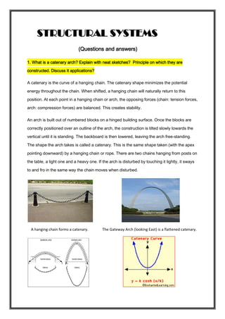
  • 1. STRUCTURAL SYSTEMS (Questions and answers) 1. What is a catenary arch? Explain with neat sketches? Principle on which they are constructed. Discuss it applications? A catenary is the curve of a hanging chain. The catenary shape minimizes the potential energy throughout the chain. When shifted, a hanging chain will naturally return to this position. At each point in a hanging chain or arch, the opposing forces (chain: tension forces, arch: compression forces) are balanced. This creates stability. An arch is built out of numbered blocks on a hinged building surface. Once the blocks are correctly positioned over an outline of the arch, the construction is tilted slowly towards the vertical until it is standing. The backboard is then lowered, leaving the arch free-standing. The shape the arch takes is called a catenary. This is the same shape taken (with the apex pointing downward) by a hanging chain or rope. There are two chains hanging from posts on the table, a light one and a heavy one. If the arch is disturbed by touching it lightly, it sways to and fro in the same way the chain moves when disturbed. A hanging chain forms a catenary. The Gateway Arch (looking East) is a flattened catenary.
  • 2. Catenary arches are often used in the construction of kilns. In this construction technique, the shape of a hanging chain of the desired dimensions is transferred to a form which is then used as a guide for the placement of bricks or other building material. 2. Write the difference between portal frame and space frame. PORTAL FRAMES: They are the most commonly used structural forms for single-storey industrial structures. They are constructed mainly using hot-rolled sections, supporting the roofing and side cladding via cold-formed purlins and sheeting rails. They may also be composed of tapered stanchions and rafters fabricated from plate elements. Portal frames of lattice members made of angles or tubes are also common, especially in the case of longer span. ‘ Portal frame construction is a method of building and designing simple structures, primarily using steel or steel-reinforced precast concrete although they can also be constructed using laminated timber such as glulam. The connections between the columns and the rafters are designed to be moment-resistant, i.e. they can carry bending forces. Because of these very strong and rigid joints some of the bending moment in the rafters is transferred to the columns. This means that the size of the rafters can be reduced or the
  • 3. span can be increased for the same size rafters. This makes portal frames a very efficient construction technique to use for wide span buildings. Portal frame construction is therefore typically seen in warehouses, barns and other places where large, open spaces are required at low cost and a pitched roof is acceptable. Generally portal frames are used for single story buildings but they can be used for low rise buildings with several floors where they can be economic if the floors do not span right across the building. Portal frames can be clad with all sorts of material but the most popular solution, for reasons of economy and speed, is some form of lightweight insulated metal cladding with cavity masonry work to the bottom 2m of the wall to provide security and impact resistance. The lightweight cladding would be carried on sheeting rails spanning between the columns of the portal frames.
  • 4. The most common form of portal frame used in the construction industry is the pinned-base frame with different rafter and column member size and with haunches at both the eaves and apex connections. SPACE FRAMES: A space frame or space structure is a truss-like, lightweight rigid structure constructed from interlocking struts in a geometric pattern. Space frames can be used to span large areas with few interior supports. Like the truss, a space frame is strong because of the inherent rigidity of the triangle; flexing loads (bending moments) are transmitted as tension and compression loads along the length of each strut. The simplest form of space frame is a horizontal slab of interlocking square pyramids built from aluminium or tubular steel struts. A stronger purer form is composed of interlocking tetrahedral pyramids in which all the struts have unit length. More technically this is referred to as an isotropic vector matrix or in a single unit width an octet truss. More complex variations change the lengths of the struts to curve the overall structure or may incorporate other geometrical shapes. Configuration of space frame build systems: • Generally square inverted pyramid modules connected at the top and bottom layers provide the most commonly used Space Frame structures • Pipes, spherical node, cone, bolt and sleeve are the common components •  There are various types of connection nodes patented by various companies in the world. Two popular nodes are solid spherical nodes per Mero system Germany and hollow spherical node per Unibat
  • 5.  Polycarbonate sheets, fiberglass reinforced plastic sheets or glazing used for covering, to provide aesthetically beautiful sky light systems . However, colour- coated steel sheets. aluminium sheets and asbestos sheets are also used  Latticed Space Frame Structures, particularly for roofs are similar to two-way concrete slab or flat plates. These latticed structures, single layer or double layer, include 3-dimensional Space Grid Structures, Domes, Barrel Vaults, Hyperbolic Parabloid Shell Structures, etc. Advantages of Space Frames: 1. One of the most important advantages of a space structure is its lightweight. This is mainly due to the fact that material is distributed spatially in such a way that the load transfer mechanism is primarily axial — tension or compression. 2. The units of space frames are usually mass produced in the factory so that they can take full advantage of the industrialized system of construction. Space frames can be built from simple prefabricated units, which are often of standard size and
  • 6. shape. Such units can be easily transported and rapidly assembled on site by semi- skilled labour. Consequently, space frames can be built at a lower cost. 3. A space frame is usually sufficiently stiff in spite of its lightness. This is due to its three-dimensional character and to the full participation of its constituent elements. 4. Space frames possess a versatility of shape and form and can utilize a standard module to generate various flat space grids, latticed shell, or even free-form shapes. Benefits: Minimum structure weight / Long clear spans & cantilevers / 1. Accommodates concentrated loads Suits irregular supports or plan geometry 2. Variable depth for roof drainage is built in 3. Pre-assembly allows project acceleration 4. Pre-finished to avoid site painting & inspection 5. All service lines can run through frame / Frame can be a feature without ceiling 6. Simple modification or dis-assembly for re-use Applications: Malls, Food courts, Transport terminals, Schools, Pools, Arenas, Entertainment, Hospitals, Hotels, Corporate & Commercial Buildings, Convention centers 3. Explain the classification of domes with neat sketches. A dome is an architectural element that resembles the hollow upper half of a sphere. The precise definition has been a matter of controversy. There are also a wide variety of forms and specialized terms to describe them. A dome can rest upon a rotunda or drum, and can
  • 7. be supported by columns or piers that transition to the dome through squinches or pendentives. A lantern may cover an oculus and may itself have another dome. Domes have a long architectural lineage that extends back into prehistory and they have been constructed from mud, snow, stone, wood, brick, concrete, metal, glass, and plastic over the centuries. The symbolism associated with domes includes mortuary, celestial, and governmental traditions that have likewise developed over time. The domes are classified into the following: 1. BRACED DOMES: They are composed either of members lying on a surface of revolution, or of straight members with their connecting points lying on such a surface; an arrangement which avoids any obstruction of the inner space. This arrangement generally results in a dome of circular base, or in one truncated into a polygonal base, though domes with elliptical or oval surface have also been used in rare cases. Types of braced domes: a) Frame or skeleton type (single layer dome) b) Truss type (or double layer dome) which is extremely rigid and provides greater resistance to buckling- suitable for very large spans. c) Stressed skin type (in which the covering forms an integral part of the structural system) and d) Formed surface type (in which bent sheets are interconnected along their edges to form the main skeleton of the dome).
  • 8. Typical shape of a dome 2. RIBBED DOMES: They consist of a number of identical radial solid or trussed (latticed) interconnected at the crown and supported in an adequate way at the foundation. Braced Rib domes: This type of roof is not economical because it does not incorporate the advantages of structural interaction of latitudinal intermediate rings. Depending on the base diameter of the dome, there may be 8 to 72 intersecting braced ribs. They are usually of constant depth. Braced ribbed domes with different braces Solid Rib domes: They are similar to braced arch domes in spatial arrangement, except that a) the meridional ribs are composed of shallower solid- web sections, rolled, built up, boxed or even diamond box shaped, b) the meridional space system is additionally integrated by intermediate rings between upper compression ring and the
  • 9. lower peripheral ring, and c) all the ribs generally terminate at the upper compression ring instead of some being carried through. Solid ribbed dome with a circular base 3. PLATE TYPE DOMES: This type of dome is also a type f Schwedler dome, with a small number of sides. Their side panels filled in by several bars, all of them in the same plane, forming a triangular network bracing. The plate type dome has the advantage that it can be used to cover rectangular areas. 4. NETWORK DOMES: They can be derived from Schwedler domes by the rotation of each polygonal ring through an angle of π/n with respect to the ring below where n=no of sides. They are theoretically better than Schwedler domes but they are much more difficult to erect. The peculiarity of network domes is that they are stable only under an odd number of sides. With an
  • 10. even number of sides the structure becomes critical. These domes can also be used to cover rectangular areas. 5.LAMELLA DOMES: They are another curvilinear system of ribbed domes, characterized by a)only a few of the ribs running from the rim to the crown of the dome as meridional spherical sector dividers, b)all other ribs running as intra-sector parallel lines, curvilinear or straight, and c)a diamond grid being thus formed. Lamella domes are structurally indeterminate. Usually these types of domes are analysed using matrix methods of structural analysis. 6. GEODESIC DOMES: A geodesic dome is a spherical or partial-spherical shell structure or lattice shell based on a network of great circles (geodesics) lying on the surface of a sphere. The geodesics intersect to form triangular elements that have local triangular rigidity and also distribute the stress across the entire structure. When completed to form a complete sphere, it is known as a geodesic sphere. Typically the design of a geodesic dome begins with an icosahedron inscribed in a sphere, tiling each triangular face with smaller triangles, then projecting the vertices of each tile to the sphere. The endpoints of the links of the completed sphere would then be the projected endpoints on the sphere's surface. If this is done exactly, each of the edges of the sub-triangles is a slightly different length, so it would require a very large number of links of different sizes. To
  • 11. minimize the number of different sizes of links, various simplifications are made. The result is a compromise consisting of a pattern of triangles with their vertices lying approximately on the surface of the sphere. The edges of the triangles form approximate geodesic paths over the surface of the dome that distributes its weight. Geodesic designs can be used to form any curved, enclosed space. Oddly-shaped designs would require calculating for and custom building of each individual strut, vertex or panel— resulting in potentially expensive construction. Because of the expense and complexity of design and fabrication of any geodesic dome, builders have tended to standardize using a few basic designs. Details of Geodesic dome geometrics 7. GRID DOMES: It uses the Hamman System. The main features and merits of the Hamman dome are as follows: a) Simple square panels of sheeting all of one size and interchangeable b) All ribs on great circles c) Ribs continuous through intersection point, thus having less joints than lamella domes d) None of the major loads carried through bolted, riveted or welded joints e) Basic theory of thin-shell dome of revolution proven to be applicable
  • 12. f) Adaptable to both relatively short-diameter and very large diameter domes g) Inherently light, as all panel loads are equal and are transmitted successively in all directions.
  • 13. Types of grid domes 4. Explain the different types of folded plates and where they are used. Folded plates are assemblies of flat plates rigidly connected together along their edges in such a way so as to make the structural system capable of carrying loads without the need for additional supporting beams along mutual edges. 1. Flat paper deforms under its own weight 2.Folded paper has greater strength and stiffness than flat paper 3. Heavy load may buckle the folded paper due 4.Secured ends add stability against
  • 14. to lack of stability buckling Types of folded plates: 1- Prismatic: if they consist of rectangular plates. 2- Pyramidal: when non-rectangular plates are used. 3- Prismoidal, triangular or trapezoidal. On the other hand, folded plates can be classified as: 1- Single. 2- Multiple. 3- Symmetrical. 4- Unsymmetrical. 5- Simple. 6- Continuous. 7- Folded plates with simple joints. 8- Folded plates with multiple joints. 9- Folded plates with opened cross sectional. 10- Folded plates with closed cross sectional. Folded Plate Behaviours: Each plate is assumed to act as a beam in its own plane, this assumption is justified when the ratio of the span "length" of the plate to its height "width" is large enough. But when this ratio is small, the plate behaves as a deep beam. Folded plates combine slab action with beam action. In length direction they act like thin inclined beams of great depth, stabilized against at top and bottom by adjoining plates. In width direction they are one-way slabs that span between adjacent plates. 1. Folded plate concept 2. Slab action in width direction 3. Slab and beam equivalent 4. Beam action in length direction
  • 15. I. Bending deformation creates compression on top and tension at the bottom II. Horizontal shear caused by top compression and bottom tension III. Vertical shear is maximum at supports and zero at mid span. Folded plate forms: Folded plates may have many one-way, two or three-way spans. They may be motivated by aesthetic or spatial objectives, or to add strength and stability to a system. In areas with snow, flat folded plates are problematic since snow can accumulate in the valleys. 1. Folded plate with one straight and one gabled edge 2.Folded plate with offset gabled edges 3. Folded plate with gabled edges offset at mid-span 4.Folded plate with vertical support folding and gables offset at mid-span 1. Three-way folded plate unit and assembly on triangular base plan
  • 16. 2. Two-way folded plate unit and assembly on square base plan 3. Three-way folded plate unit and assembly on hexagonal base plan 5. Explain the types of curtain walls and write their components. A curtain wall is an outer covering of a building in which the outer walls are non-structural, but merely keep out the weather. As the curtain wall is non-structural it can be made of a lightweight material reducing construction costs. When glass is used as the curtain wall, a great advantage is that natural light can penetrate deeper within the building. The curtain wall façade does not carry any dead load weight from the building other than its own dead load weight. The wall transfers horizontal wind loads that are incident upon it to the main building structure through connections at floors or columns of the building. A curtain wall is designed to resist air
  • 17. and water infiltration, sway induced by wind and seismic forces acting on the building and its own dead load weight forces. Curtain walls are typically designed with extruded aluminium members, although the first curtain walls were made of steel. The aluminium frame is typically in filled with glass, which provides an architecturally pleasing building, as well as benefits such as day lighting. However, parameters related to solar gain control such as thermal comfort and visual comfort are more difficult to control when using highly-glazed curtain walls. Other common in fills include: stone veneer, metal panels, louvers, and operable windows or vents. Curtain walls differ from store-front systems in that they are designed to span multiple floors, and take into consideration design requirements such as: thermal expansion and contraction; building sway and movement; water diversion; and thermal efficiency for cost-effective heating, cooling, and lighting in the building. Types of curtain walls and their components Grid construction: The majority of curtain walls consist of a rectangular grid of vertical and horizontal members, framing openings filled with inserts or glass. The inserts and glazing are the space-enclosing elements of the grid curtain wall, while the grid itself forms the framework, within which these are installed. Normally only the grid is attached to the supporting structure, to which it hen transfers the entire weight of the curtain wall plus possible wind loads. Only in a few special cases are the inserts fastened to the structure directly. Such auxiliary connections reduce the load on the grid, which, however continues to perform its primary function of framing the space-enclosing elements on the wall. The grid is clearly expressed in elevation and gives the curtain wall facade its characteristic structure. It has thus become a distinguishing feature in curtain wall design.
  • 18. Spandrel panels-fixed glazing-windows Spandrel panels-windows (pivoted sash) Panel construction: This term will be applied to wall assemblies consisting of large, story- high panels fastened either directly or indirectly- by means of secondary framing- to the supporting structure. Flat sheet The only components of panel curtain walls are the panels themselves which combine the twin functions of enclosing space and transferring the dead and live loads to the supporting structure. The most important structural characteristic of such panels is their jointless, continuous outer surface.
  • 19. Concrete Window openings, so far as they are structurally feasible, are cut out of the middle of the panel, with which the window frame is rigidly connected. The panels are joined directly, without the use of intermediate elements. The most important design characteristic of panel systems is again the virtually continuous outer surface, broken only by the joints between units. Formed sheet Figures: Panel constructions 5. Write short notes on: A beam is a structural element that is capable of withstanding load primarily by resisting bending. The bending force induced into the material of the beam as a result of the external loads, own weight and external reactions to these loads is called a bending
  • 20. moment. Internally, beams experience compressive, tensile and shear stresses as a result of the loads applied to them Above the supports, the beam is exposed to shear stress. There are some reinforced concrete beams that are entirely in compression. These beams are known as prestressed concrete beams, and are fabricated to produce a compression more than the expected tension under loading conditions A) SIMPLY SUPPORTED BEAMS: A beam that has hinged connection at one end and roller connection in other end is called simply supported beam, so when transverse loads are applied they resists by generating reactive forces on their supports. The beams may be made from several usable engineering materials such commonly among them are as follows:  Metal  Wood  Concrete  Plastic The beams are said to be simply supported if their supports creates only the translational constraints.
  • 21. B) SLABS: A concrete slab is a common structural element of modern buildings. Horizontal slabs of steel reinforced concrete, typically between 10 and 50 centimetres thick, are most often used to construct floors and ceilings, while thinner slabs are also used for exterior paving. In many domestic and industrial buildings a thick concrete slab, supported on foundations or directly on the subsoil, is used to construct the ground floor of a building. In high rise buildings and skyscrapers, thinner, pre-cast concrete slabs are slung between the steel frames to form the floors and ceilings on each level. Design: For a suspended slab, there are a number of designs to improve the strength-to-weight ratio. In all cases the top surface remains flat, and the underside is modulated:  Corrugated, usually where the concrete is poured into a corrugated steel tray. This improves strength and prevents the slab bending under its own weight. The corrugations run across the short dimension, from side to side.  A ribbed slab, giving considerable extra strength on one direction.  A waffle slab, giving added strength in both directions.  A one way slab has structural strength in shortest direction. A two way slab has structural strength in two directions Reinforcement design  A one way slab needs moment resisting reinforcement only in its short-direction. Because, the moment along long axes is so small that it can be neglected. When the ratio of the length of long direction to short direction of a slab is greater than 2 it can be considered as a one way slab.
  • 22.  A two way slab needs moment resisting reinforcement in both directions. If the ratio of the lengths of long and short side is less than one then moment in both directions should be considered in design. Construction: A concrete slab may be prefabricated or in situ. Prefabricated concrete slabs are built in a factory and transported to the site, ready to be lowered into place between steel or concrete beams. They may be pre-stressed (in the factory), post- stressed (on site), or unstressed. It is vital that the supporting structure is built to the correct dimensions, or the slabs may not fit. In situ concrete slabs are built on the building site using formwork - a type of boxing into which the wet concrete is poured. If the slab is to be reinforced, the rebars are positioned within the formwork before the concrete is poured in. Plastic tipped metal, or plastic bar chairs are used to hold the rebar away from the bottom and sides of the form-work, so that when the concrete sets it completely envelops the reinforcement. For a ground slab, the form-work may consist only of sidewalls pushed into the ground. For a suspended slab, the form-work is shaped like a tray, often supported by a temporary scaffold until the concrete sets. The formwork is commonly built from wooden planks and boards, plastic, or steel. On commercial building sites today, plastic and steel are more common as they save labour. On
  • 23. low-budget sites, for instance when laying a concrete garden path, wooden planks are very common. After the concrete has set the wood may be removed, or left there permanently. D) CABLE STRUCTURES: Form of long-span structure that is subject to tension and uses suspension cables for support. Highly efficient, cable structures include the suspension bridge, the cable-stayed roof, and the bicycle-wheel roof. The graceful curve of the huge main cables of a suspension bridge is almost a catenary, the shape assumed by any string or cable suspended freely between two points. The cable-stayed roof is supported from above by steel cables radiating downward from masts that rise above roof level. The bicycle- wheel roof involves two layers of tension cables radiating from an inner tension ring and an outer compression ring, which in turn is supported by columns. In general, the same t yp e s of sheathing used with copper based systems can be used with glass-based systems. The systems may include aerial cables, submerged cables, rodent-resistant cables, and o t h e r types of cables. There is a lack of s t a n d a r d i z a t i o n in the area of cable sheath design, but as the technology matures, standardization undoubtedly will take place. Cable Selection: The most im p o rt a n t mechanical features consider to selecting in a cable are as follows: a) Tensile strength; b) Adequate strength-member selection; c) Bending radius; d) Support requirements;
  • 24. e) Environmental specifications; f) Length of continuous run available; g) Lengths that can be safely pulled in conduits and raceways; h) Probability of fiber breakage; i) Compression strength. Cables designed to contain electrical conductors and optical fibers are also feasible and generally available. For example, twisted-pair wires for signalling applications, or to carry electrical power to optical repeaters along the cable route. Cable Structure Cable Structure with pylons E) SHEAR FORCE AND BENDING MOMENT: Shear force is an internal force in any material which is usually caused by any external force acting perpendicular to the material, or a force which has a component acting tangent to the material. The Shear Force at the cross section of the beam may be defined as the unbalanced vertical force to the right or left of the section. A bending moment exists in a structural element when a moment is applied to the element so that the element bends. Moments are calculated by multiplying the external vector forces (loads or reactions) by the vector distance at which they are applied. When analysing an entire element, it is sensible to calculate moments at both ends of the element, at the beginning, centre and end of any uniformly distributed loads, and directly underneath any point loads. Of course any "pin-joints" within a structure allow free rotation, and so zero
  • 25. moment occurs at these points as there is no way of transmitting turning forces from one side to the other. If clockwise bending moments are taken as negative, then a negative bending moment within an element will cause "sagging", and a positive moment will cause "hogging". It is therefore clear that a point of zero bending moment within a beam is a point of contraflexure—that is the point of transition from hogging to sagging or vice versa. Bending moment varies linearly over unloaded sections, and parabolically over uniformly loaded sections. The Bending Moment at the cross section of the beam may be defined as the algebraic sum of the moments of the forces, to the right or left of the section.
  • 26. Construction 1. Construction is the process of constructing a building or infrastructure.Construction differs from manufacturing in that manufacturing typically involves mass production of similar items without a designated purchaser, while construction typically takes place on location for a known client. Construction as an industry comprises six to nine percent of the gross domestic product of developed countries. 2. Construction starts with planning,[citation needed] design, and financing; and continues until the project is built and ready for use. Large-scale construction requires collaboration across multiple disciplines. An architect normally manages the job, and a construction manager, design engineer, construction engineer or project manager supervises it. 3. For the successful execution of a project, effective planning is essential. Those involved with the design and execution of the infrastructure in question must consider zoning requirements, the environmental impact of the job, the successful scheduling, budgeting, construction-site safety, availability and transportation of building materials, logistics, inconvenience to the public caused by construction delays and bidding, etc. The largest construction projects are referred to as megaprojects. Form is the shape, visual appearance, or configuration of an object. In a wider sense, the form is the way something is or happens. Formwork is the term given to either temporary or permanent molds into which concrete or similar materials are poured. In the context of concrete construction, the falsework supports the shuttering molds. Formwork comes in several types: Traditional timber formwork. The formwork is built on site out of timber and plywood or moisture- resistant particleboard. It is easy to produce but time-consuming for larger structures, and the plywood facing has a relatively short lifespan. It is still used extensively where the labour costs are lower than the costs for procuring reusable formwork. It is also the most flexible type of formwork, so even where other systems are in use, complicated sections may use it. Engineered Formwork System. This formwork is built out of prefabricated modules with a metal frame (usually steel or aluminium) and covered on the application (concrete) side with material having the wanted surface structure (steel, aluminum, timber, etc.). The two major advantages of formwork systems, compared to traditional timber formwork, are speed of construction (modular systems pin, clip, or screw together quickly) and lower life-cycle costs (barring major force, the frame is almost indestructible, while the covering if made of wood; may have to be replaced after a few - or a few dozen - uses, but if the covering is made with steel or aluminium the form can achieve up to two thousand uses depending on care and the applications). Re-usable plastic formwork. These interlocking and modular systems are used to build widely variable, but relatively simple, concrete structures. The panels are lightweight and very robust. They are especially suited for low-cost, mass housing schemes. Permanent Insulated Formwork. This formwork is assembled on site, usually out of insulating concrete forms (ICF). The formwork stays in place after the concrete has cured, and may provide advantages in
  • 27. terms of speed, strength, superior thermal and acoustic insulation, space to run utilities within the EPS layer, and integrated furring strip for cladding finishes. ″Coffor″ is a structural stay-in-place formwork system to build constructions in concrete. It is composed of two filtering grids reinforced by vertical stiffeners and linked by articulated connectors that can be folded for transport. Any type of construction can be built with Coffor: individual houses, multi-story buildings including high-rise buildings, industrial, commercial or administrative buildings. Several types of civil works can be done with Coffor. Coffor is delivered completely assembled from the factory. No assembly is necessary on the construction site. Stay-In-Place structural formwork systems. This formwork is assembled on site, usually out of prefabricated fiber-reinforced plastic forms. These are in the shape of hollow tubes, and are usually used for columns and piers. The formwork stays in place after the concrete has cured and acts as axial and shear reinforcement, as well as serving to confine the concrete and prevent against environmental effects, such as corrosion and freeze-thaw cycles. Flexible formwork - In contrast to the rigid moulds described above, flexible formwork is a system that uses lightweight, high strength sheets of fabric to take advantage of the fluidity of concrete and create highly optimised, architecturally interesting, building forms. Using flexible formwork it is possible to cast optimised structures that use significantly less concrete than an equivalent strength prismatic section,[1] thereby offering the potential for significant embodied energy savings in new concrete structures.
  • 28. UNIT 2 ARCH 1. An arch is a curved structure that spans a space and may or may not support weight above it.Arch may be synonymous with vault, but a vault may be distinguished as a continuous arch forming a roof. Arches appeared as early as the 2nd millennium BC in Mesopotamian brick architecture,and their systematic use started with the Ancient Romans who were the first to apply the technique to a wide range of structures. An arch is a pure compression form. 2. It can span a large area by resolving forces into compressive stresses and, in turn eliminating tensile stresses. This is sometimes referred to as arch action.As the forces in the arch are carried to the ground, the arch will push outward at the base, called thrust. 3. As the rise, or height of the arch decreases, the outward thrust increases. In order to maintain arch action and prevent the arch from collapsing, the thrust needs to be restrained, either with internal ties or external bracing, such as abutments. 4. An arch is held in place by the weight of all of its members, making construction problematic. One answer is to build a frame (historically, of wood) which exactly follows the form of the underside of the arch. This is known as a centre or centring. Voussoirs are laid on it until the arch is complete and self-supporting. 5. For an arch higher than head height, scaffolding would be required, so it could be combined with the arch support. Occasionally, arches would fall down when the frame was removed if construction or planning had been incorrect.
  • 29. Typesofarches: Arches are constructed in four basic shapes that frame and support doors, windows, porches, and other wall openings:  Flat arch  Triangular arch  Round arch  Pointed arch Flatarch: An arch having a horizontal intrados with voussoirs radiating from a centre below, often built with a slight camber to allow settling is called a flat or jack arch. French arch: A flat arch with voussoirs inclined to the same angle at each side of the centre. The mortar joints do not, therefore, radiate to a common centre. Not, technically, a proper arch, and of weak form. Triangulararch: It is a primitive form of arch consisting of two stones laid diagonally to support each other over an opening. Hence, the span is limited by the size of the available material.
  • 30. VAULTS: Vaults A Vault (The parts of a vault exert a thrust that require a counter resistance. When vaults are built underground, the ground gives all the resistance required. However, when the vault is built above ground, various replacements are employed to supply the needed resistance. An example are the thicker walls used in the case of barrel or continuous vaults. Buttresses are used to supply resistance when intersecting v The simplest kind of vault is the barrel vault (also called a wagon or tunnel vault) which is generally semicircular in shape. The barrel vault is a continuous arch, the length being greater than its diameter. As in building an arch, a temporary support is needed while rings of voussoirs are constructed and the rings placed in position. Until the topmost voussoir, the keystone, is positioned the vault is not self-supporting. 1. A vault is a ceiling of brick, stone, or concrete built in the principle of the arch. A tunnel vault, or barrel vault, is a tunnel-like, semi- cylindrical extension of an arch, which may be thought of as an unbroken series of arches pressed together, one behind the other. 2. It cannot be lighted except at the ends without being structurally weakened, because, as in an arch, continuous abutment must be applied to absorb the thrust carried down along the haunches to the walls supporting it. 3. However, arches may be introduced in the supporting walls and transverse ribs may be inserted in the vault to concentrate thrust at a few strongly buttressed points, thereby permitting a reduction of weight and thrust in the segments of vaulting between the ribs. 4. If a barrel vault is intersected at right angles by another barrel vault of the same size, a cross vault, or groin vault, is formed. 5. This is a very efficient form of vaulting allowing full illumination from the sides. 6. Groin vaults also allow a great saving in material and labour over the simple barrel vault; thrust is concentrated along the groins (the four
  • 31. diagonal edges formed along the points where the barrel vaults intersect), so the vault need only be abutted at its four corners. Barrel or Tunnel Vault Groin Vault (from above) Groin Vault (from below) Types of vaults: Barrel Vault:A barrel vault is the simplest of the vaults and is the base design for many vaults that have a more intricate design. It consists of an on-going series of semi-circular arches. One is directly behind another, causing it to look like a half of a barrel. In some instances, it is described as resembling a tunnel. Groin Vault:A groin vault is created by two barrel vaults intersecting at right angles. The arches of groin vaults are round or pointed. It is also known as a cross vault. Rib Vault:A vault reinforced by masonry ribs is known as a rib vault. When this type of vault has two masonry ribs dividing it into four sections, it is
  • 32. called a quadripartite rib vault. A vault divided by three masonry ribs that make six sections is called a sexpartite rib vault. DOMES: Domes are curved architectonic structures with no angles or corners, similar to the upper half of a sphere. Despite their apparent fragility, domes are strong structures and have been used in buildings since ancient times, according to PBS Online. In Europe, the earliest domes were made of stone. The Roman Pantheon, built almost 2,000 years ago, is a good example of early dome engineering. Indigenous peoples in Ethiopia and other places have used curved bows to create their huts, creating a primitive yet effective dome Trusses 1. A truss is a structure comprising one or more triangular units constructed with straight members whose ends are connected at joints referred to as nodes. External forces and reactions to those forces are considered to act only at the nodes and result in forces in the members which are either tensile or compressive forces. Moments (torsional forces) are explicitly excluded because, and only because, all the joints in a truss are treated as revolutes. 2. A planar truss is one where all the members and nodes lie within a two dimensional plane, while a space truss has members and nodes extending into three dimensions. Characteristics of trusses A truss is composed of triangles because of the structural stability of that shape and design. A triangle is the simplest geometric figure that will not change shape when the lengths of the sides are fixed.[1] In comparison,
  • 33. both the angles and the lengths of a four-sided figure must be fixed for it to retain its shape. There are two basic types of truss: 1. The pitched truss, or common truss, is characterized by its triangular shape. It is most often used for roof construction. Some common trusses are named according to their web configuration. 2. The chord size and web configuration are determined by span, load and spacing.The parallel chord truss, or flat truss, gets its name from its parallel top and bottom chords. It is often used for floor construction. 3. A combination of the two is a truncated truss, used in hip roof construction. A metal plate-connected wood truss is a roof or floor truss whose wood members are connected with metal connector plates. Space frame truss  A space frame truss is a three-dimensional framework of members pinned at their ends. A tetrahedron shape is the simplest space truss, consisting of six members which meet at four joints.Large planar structures may be composed from tetrahedrons with common edges and they are also employed in the base structures of large free- standing power line pylons Rigid frames structures . Rigid frame structures are built at the site which may or may not be poured monolithically. . Rigid frame structures provide more stability. . Rigid frame structures resist rotations more effectively Advantages Rigid frame structures feature positive and negative bending moments throughout the structure due to interaction of walls, beams and slabs.
  • 34. Braced frame structures Braced frame structures resist lateral forces by the bracing action of diagonal members. . Braced frame structures are used toresist sideway forces. . Buildings are braced by inserting diagonal structural members into the rectangular areas of a structural frame. Advantages To stabilize the frame against earthquakes and strong winds. Lateral forces are resisted by axial actions of bracing and columns. More efficient than a rigid frame. Portal structural frames It resembles like a door. Multi-story, multi-bay portal frames are commonly used for commercial and industrial construction.The members are usually made up of curved laminates and the members are thickened in the region of the knee or eaves joint to allow for the large moment. Advantages of Frames:  Optimum use of floor space.  Easy construction.  Rapid construction.  Economical for high rise buildings.  Erected by steel and/or reinforced concrete Disadvantages Generally, frames are flexible structures and lateral deflections control the design process for buildings with greater than about 4 stories. The concrete frames are 8 times stiffer than steel frames of the same strength. Span lengths are limited when using normal reinforced concrete (generally less than about 13 m, but up to about 15 m).
  • 35. UNIT 3 Defining structures In the context of the following, a structure is loosely defined as a physical object, or a system thereof, that enables people crossing voids, lift goods, defines space etc. Its purpose of function is to supply the strength, stiffness, and rigidity to fulfill the aforementioned functions Defining structures Generally speaking: structures form parts of a work of architecture Structures are closely related to architecture, space and expression Structures can form the envelope, may control the inflow of daylight, potentially control the relation between the inside and the outside etc. Relationship between architecture and structure For classical Greek architecture, the architectural expression was strongly tied to the beams and columns, and their proportions. With modernism, things changed e.g.: Perret and Le Corbusier separated constructive from functional/expressive elements. Separation into purely structural and abstractly aesthetic. Problems raised by modernism How to separate the structural elements from the aesthetical ones Where does the stru ture egi , a d here does it e d… While the answer might easy when it comes, e.g. to skeleton structures, it is ot o ious for, e.g. a do e… The structure dome needs more than the topology dome Structural form and its logic For civil engineers, structural form gravitates around central topics as Strength / Stiffness / Stability / Durability in the broader sense In engineering practice, these topics are, as much as possible, orthogonalized / Strength is attributed to the material / Stiffness is a sectional quality / Stability relates to static system / Durability is related to detailing Two main principles
  • 36. Form inherently resides in the material, and is made explicit by respecting the qualities and properties (the nature) of that material Form is conceived irrespectively of the material, and is as such free to evolve without preconditions for realization in a specific material Architecture Architecture is both the process and product of planning, designing and constructing space that reflects functional, social, and aesthetic considerations. It requires the manipulation and coordination of material, technology, light, and shadow. Architecture often involves the manipulation of space, volume, texture, light, shadow, and abstract elements in order to achieve an aesthetic end. This distinguishes it from applied science or engineering, which usually concentrate more on the functional and feasibility aspects of a design, rather than its aesthetics. Architects must have the skills to design a large scope of projects, from a stadium to a residential house. Many architectural works are also seen as cultural and political symbols, or works of art. The role of the architect, though changing, has been central to the design and implementation of the environments in which people live. Aesthetic theory of Expression of structural function in architectural form  The principle is that the shape of a building or object should be primarily based upon its intended function or purpose. Form follows function is a principle associated with modern architecture and industrial design in the 20th century. The principle is that the shape of a building or object should be primarily based upon its intended function or purpose.  Architecture is not merely a slavery to the past art, not is it blind originality. It has to be a perfect blend usability, beauty and economy. Architecture has always been the result of the delicate balance et ee art a d s ie e… ut it has ee ore of an Art than science. An Architect is an artist who sets out to remodel the world to ake is ore perfe t for hu a ha itatio …  The personality of an architect is reflected through his creations. We can gauge his temperament by looking at the way the structure is designed, both internally as well as externally. An architect takes care
  • 37. of human need, interests, sentiments & values of his clients while designing the Structures  Functionality should always be giver higher priority than form. But this does not always happen. An Architect might be tempted to create sazzy designs which might be prohibitively expensive or unusable. However, it is the duty of an Architect to design a structure in a way that it is both functional, durable and trendy. Compromises have to be made. But an Architect should never indulge himself in creating extravagant forms which might be aesthetically beautiful but hi h do ot ser e their fu tio al purpose… Architecture is a design process which involves planning, designing, creating, erecting, constructing and executing construction of various types of buildings that are functionally efficient, economically viable and aesthetically pleasing. The two most important factors in the design of a building are Form and Function. Functionality is the most important aspect of building design. The other aspect is building form or aesthetics. Aesthetics is the branch of philosophy that deals with the nature and expression of beauty. Aesthetics is one of the major principle of Architecture that students and professionals alike have to worship. It concerns beauty or appreciation of beauty. In other words, it is a philosophy behind a pleasing appearance. A set of principles followed by the Architectural designers or any designers for that matter for the evolution of the end product that is aesthetically pleasing to the eye, is called aesthetics. It is directly influenced by the artistic taste of an individual. Aesthetic Components of Architecture Aesthetics, Architecture, balance, creativity, deconstructivism, design, patter n, proportionality, rhythm, scale, symmetry, unity GEOMETRY OF FORM AND STRUCTURAL FUNCTION. The structural form of buildings can simply be defined as the geometrical configuration of the space involved by the structure. However, within a
  • 38. similar external visible geometry, different structural actions could be responded by structure under the same kind of loads. Various Capacities of different materials, internal detailing of cross-sections, the manner and sequence of construction and the dimensions of the structure can cause different structural actions in similar overall geometry of the structures. Therefore, the geometrical configuration is only one aspect of the structural form. Behavior of Structural Elements Major forms of masonry structures are arches, vaults, domes and walls. They reflect certain structural factors, through their characteristic thickness. Their thickness was directed by the coarseness of their constituent materials: stone, brick and mortar joints. Their inability to resist tensile stresses required widening of their cross-sections so that compression would reduce the effect of potential bending. Substantial thickness was often intuitively felt necessary to prevent buckling. Equilibrium 1. Equilibrium is the condition of a system in which all competing influences are balanced. A structure is in equilibrium when all forces or moments acting upon it are balanced. Every structure that can be seen to remain standing on a daily basis is in equilibrium. It is at rest and each of its members, combination of its members or any part of a member that is supporting a load, are also at rest. 2. There is a net result of zero in all directions for all of the applied loads and reactions. Architectural structures are normally stationary. Most clients, building officials and designers prefer that their structures remain static rather than move dynamically. 3. There are specific loading conditions which are dynamic loads, but in each and every case a return to a stable and static state is desirable. Such a condition is known as Equilibrium. Advanced structural systems is an opportunity to explore the relationship between architecture and innovative structural form. It is about advanced structural systems such as
  • 39. membranes, grillage systems, structural glass which helps in developing and integrating imaginative structural form that would enhance and complement the architectural solution.
  • 40. UNIT 4 Single-Layer and Double-Layer Grids Single layer grid A grid can be comprised of two or more sets of parallel members intersecting each other at an angle and loaded perpendicular to their planes. If all the members of a grid are in the same plane, it is called a single-layer grid. There are different types of single-layer grid used as the main structural systems for roofs and floors. These interconnected patterns consist of two-way, three-way or four-way configurations, with the most common pattern being rectangular grid in which the intersecting elements are perpendicular to each other. The diagonal grid, in which the members are oriented in an oblique manner to the supporting structure along the edge, has great rigidity (or stiffness), i.e., substantial reduction in deflection. two way grid
  • 41. Four-Way Grids - The three-way single-layer grids are generally used for larger span or when the structure is subjected to large concentrated loads. This system has a more even stress distribution that the two-way grids. The four-way grids are made of a combination of rectangular and diagonal grids. These systems are not commonly used. For up to almost 30 ft span single-layer grids are efficient, however, for larger spans double-layer grids are more appropriate, which can be used for spans up to about 300 ft. Since grids are very rigid structures, they require members that are shallower than planar systems. The span to depth ratio for single layer rectangular grids is about 30 and for diagonal grids is about 40. Double layer grids (DLGs) are extensions of single-layer grid systems, which consist of two sets of parallel beams connected to each other at right or oblique angles and loaded by forces perpendicular to the plane of the grid. Even though DLGs are customarily made of parallel planes, it is possible to create free-forms by modifying the shape of the top and bottom layers independently. There are generally two main types of DLGs: Direct (Truss) Grids: In this type of system the members of the top and bottom layers are in the same plane resulting in a series of intersecting planar trusses. Space Grids: These are made of a series of polyhedral units with triangular, square, pentagonal or hexagonal bases. DLGs can be used for floors or roofs of multi-story buildings (though a majority of systems are used for roofs). The roof system in most cases consists of purlins supported by joints, however, in some cases the top layer directly supports the roof. In addition, DLGs have been used for vertical or inclined walls.
  • 42. obert Le Ricolais, a French engineer, designed numerous three-way grids. The three-way grids, made of interconnected tetrahedra and octahedra, are referred to as Le Ricolais space grids which are made of identical members interconnected with identical connectors. Double layer grid configuration can also be considered to have been generated by the close packing of platonic solids such as tetrahedra, octahedra, etc., placed next to each other and connected at joints (sometimes with additional members). RIBBED DOMES Domes have been used to cover structures since ancient times. Arab and Muslim builders adopted the use of domes from previous traditions in their buildings, and introduced several innovations of their own. One such innovation started in Muslim Spain in the 10th century. It is the construction of Star Ribbed Domes, where a pair of parallel arches is rotated to intersect and produce a star pattern. To avoid the congestion at the apex of a dome resulting from many ribs meeting at the same point when rotated, Arab-Muslim builders used two arches which were separated from each other. By rotating this pair of arches, we divide the dome surface into star-like shapes composed of regular polygon cells. The central polygon is a regular convex polygon, and when parts of the ribs are omitted at the center, these polygons turn into regular stars. Next to the central polygon, there is one row of triangular cells, followed by a number of kite shaped cells which increase in size as we move from the center of the dome towards its edges. The number of the different shapes of these cells equals to the number of rotations applied to the original pair of arches Plate-type domes are usually described as domes, totally or partly consisting of planes with more than 3 edges, braced by structural cladding such as plates or by bars in a triangular pattern. It seems that this concept may be extended to regarding the plate dome, or plate structure in general, as an independent and just as basic a structural family as the lattice structure, so basic in fact that it is the exact dual of the lattice structure. Plate domes are highly efficient structurally when shaped, proportioned and supported to transmit loads without bending or twisting. Such domes should satisfy the following conditions:
  • 43.  The plate should not be so thin that deformations would be large compared with the thickness.  Shearing stresses normal to the surface should be negligible.  Points on a normal to the surface before it is deformed should lie on a straight line after deformation.  And this line should be normal to the deformed surface. Stress analysis usually is based on the membrane theory, which neglects bending and torsion. Despite the neglected stresses, the remaining stresses are in equilibrium, except possibly at boundaries, supports, and discontinuities. At any interior point of a thin-shell dome, the number of equilibrium conditions equals the number of unknowns. Thus, in the membrane theory, a plate dome is statically determinate. Avoid concentrated and abruptly changing loads.  Change curvature gradually.  Keep discontinuities to a minimum.  Provide reactions that are tangent to the dome.  Make certain that the reactions at boundaries are equal in magnitude and direction to the shell forces there.  Also, at boundaries, ensure, to the extent possible, compatibility of shell deformations with deformations of adjoining members, or at least keep restraints to a minimum. A common procedure is to use as a support a husky ring girder and to thicken the shell gradually in the vicinity of this support. Similarly, where a circular opening is provided at the crown, the opening usually is reinforced with a ring girder, and the plate is made thicker than necessary for resisting membrane stresses A geodesic dome  Typically a geodesic dome design begins with an icosahedron inscribed in a hypothetical sphere, tiling each triangular face with smaller triangles, then projecting the vertices of each tile to the sphere. The endpoints of the links of the completed sphere are the projected endpoints on the sphere's surface. If this is done exactly, sub-triangle edge lengths take on many
  • 44. different values, requiring links of many sizes. To minimize this, simplifications are made. The result is a compromise of triangles with their vertices lying approximately on the sphere. The edges of the triangles form approximate geodesic paths over the surface of the dome.  Geodesic designs can be used to form any curved, enclosed space. Standard designs tend to be used because unusual configurations may require complex, expensive custom design of each strut, vertex and panel.  Panelized domes are constructed of separately framed timbers covered in plywood. The three members comprising the triangular frame are often cut at compound angles in order to provide for a flat fitting of the various triangles. Holes are drilled through the members at precise locations and steel bolts then connect the triangles to form the dome. These members are often 2x4's or 2x6's, which allow for more insulation to fit within the triangle. The panelized technique allows the builder to attach the plywood skin to the triangles while safely working on the ground or in a comfortable shop out of the weather. This method does not require expensive steel hubs.  Temporary greenhouse domes have been constructed by stapling plastic sheeting onto a dome constructed from one-inch square beams. The result is warm, movable by hand in sizes less than 20 feet, and cheap. It should be staked to the ground to prevent it being moved by wind.  Steel-framework domes can be easily constructed of electrical conduit. One flattens the end of a strut and drills bolt holes at the needed length. A single bolt secures a vertex of struts. The nuts are usually set with removable locking compound, or if the dome is portable, have a castle nut with a cotter pin. This is the standard way to construct domes for jungle gyms.  Concrete and foam plastic domes generally start with a steel framework dome, wrapped with chicken wire and wire screen for reinforcement. The chicken wire and screen is tied to the framework with wire ties. A coat of material is then sprayed or molded onto the frame. Tests should be performed with small squares to achieve the correct consistency of concrete or plastic. Generally, several coats are necessary on the inside and outside. The last step is to saturate concrete or polyester domes with a thin layer of epoxy compound to shed water.
  • 45.  Some concrete domes have been constructed from prefabricated, prestressed, steel-reinforced concrete panels that can be bolted into place. The bolts are within raised receptacles covered with little concrete caps to shed water. The triangles overlap to shed water. The triangles in this method can be molded in forms patterned in sand with wooden patterns, but the concrete triangles are usually so heavy that they must be placed with a crane. This construction is well-suited to domes because there is no place for water to pool on the concrete and leak through. The metal fasteners, joints, and internal steel frames remain dry, preventing frost and corrosion damage. The concrete resists sun and weathering. Some form of internal flashing or caulking must be placed over the joints to prevent drafts. A Braced Frame is a structural system which is designed primarily to resist wind and earthquake forces. Members in a braced frame are designed to work in tension and compression, similar to a truss. Braced frames are almost always composed of steel members. Most braced frames are concentric. This means that, where members intersect at a node, the centroid of each member passes through the same point. Concentrically Braced Frames can further be classified as either Ordinary or Special. Ordinary concentric braced frames (OCBFs) do not have extensive requirements regarding members or connections, and are frequently used in areas of low seismic risk. OBCF steel frame buildings originated in Chicago and reinforced concrete frames originated in Germany and France - areas where earthquakes were not an engineering consideration.[1] Accordingly, special concentrically or eccentrically braced frames were later developed with extensive design requirements, and are frequently used in areas of high seismic risk. The purpose of the concentrically- or eccentrically-braced design is to ensure adequate ductility (i.e., to stretch without breaking suddenly). Folded structures are spatial structures formed by the elements in the plane, different in form and materialization. Folded structures differ in: geometric form, the form of a base over which they are performed, the manner of performance, methods of forming stiffness, function and position in the building, and the material they are made of. By using folded structures different spatial forms can be made. The straight elements forming a folded construction can be of various shapes: rectangular,
  • 46. trapezoidal or triangular. By combining these elements we get different forms resulting in a variety of shapes and remarkable architectural expression. Based on geometric shape folded structures can be divided into (Fig. 1): 1. folded plate surfaces, 2. folded plate frames, 3. spatial folded plate structures. Folded structures in the plane are the structures in which all the highest points of the elements and all the elements of the lowest points of the folded structure belong to two parallel planes. Frame folded structures represent constructional set in which the elements of each segment of the folds mutually occupy a frame spatial form. This type of folded structure is spatial organization of two or more folds in the plane. Spatial folded structures are the type of a structure in which a spatial constructive set is formed by combining mutually the elements of a folded structure. The shape of folded structures affects the transmission of load and direction of relying of folded structures. Based on these parameters we can do the division in late structure,
  • 47. Unit – V Space frames: Folded plates, shells, cyclonical shells, Hyperbolic paraboloids, free forms. Cable structures: Simply curved suspended roofs, combination of cables and struts Space frames: A space frame is a structure system assembled of linear elements so arranged that forces are transferred in three dimensional manner. In some cases, the constituent element may be two-dimensional. Macroscopically a space frame often takes the form of a flat or curved surface. Basic Concepts The space frame can be formed either in a flat or a curved surface. The earliest form of space frame structures is a single layer grid. By adding intermediate grids and including rigid connecting to the joist and girder framing system, the single layer grid is formed. The major characteristic of grid construction is the Omni-directional spreading of the load as opposed to the linear transfer of the load in an ordinary framing system. Since such load transfer is mainly by bending, for larger spans, the bending stiffness is increased most efficiently by going to a double layer system. The load transfer mechanism of curved surface space frame is essentially different from the grid system that is primarily membrane-like action. Space frames are double layered grids, excellent in appearance with large column free spaces. All type of elegant shape could be made by these systems using variety of grids. Two-way actions of space frames provide both economy and enormous spanning capability. Space frames were independently developed by Alexander Graham Bell around 1900 and Buckminster Fuller in the 1950s.Buckminster Fuller's focus was architectural structures and has had more lasting influence. Types of Space frames: They are broadly classified into three categories: - Skeleton/ braced framework: e.g. domes, barrel vaults, double and multiplier grids, braced plates. They are the most popular and innumerable combinations and variations are possible following regular geometric forms -Stressed skin systems: e.g. Skin folded plate and stressed skin domes and barrel vaults, pneumatic structures - Suspended/cable/membranestructures: e.g. cable roofs
  • 48. Enormous spanning capability Light weight High aesthetics High resale value Higher safety factor Extension with additional unit Applications: Space frame is used for commercial and industrial buildings, auditoriums, airport hangers, sport stadium, sky lights, mosque, lighting towers, petrol pumps, canopies, exhibition hall and atriums. Notable examples of buildings based on space frames are: Stansted Airport, Foster and Partners Bank of China Tower, Louvre Pyramid, I.M.Pei Biosphere2 in Oracle, Arizona Big Hangar for Barcelona SHELLS A shell is a type of structural element which is characterized by its geometry, being a three-dimensional solid whose thickness is very small when compared with other dimensions, and in structural terms, by the stress resultants calculated in the middle plane displaying components which are both coplanar and normal to the surface. Essentially, a shell can be derived from a plate by two means: by initially forming the middle surface as a singly or doubly curved surface and by applying loads which are coplanar to a plate's plane which generate significant stresses. The most popular types of thin-shell structures are:
  • 49. 1. Concrete shell structures, often cast as a monolithic dome or stressed ribbon bridge or saddle roof 2. Lattice shell structures, also called grid shell structures, often in the form of a geodesic dome or a hyperboloid structure 3. Membrane structures, which include fabric structures and other tensile structures, cable domes, and pneumatic structures. Types and Forms of Shell Structure Folded Plates /Barrel Vaults/ Short Shells /Domes of Revolution/ Folded Plate Domes /Intersection Shells/ Warped Surfaces /Combinations Shell Arches3 Barrel Shells 1. The elements of a barrel shell are: (1) The cylinder, (2) The frame or ties at the ends, including the columns, and (3) The side elements, which may be a cylindrical element, a folded plate element, columns, or all combined. For the shell shown in the sketch, the end frame is solid and the side element is a vertical beam. 2. A barrel shell carries load longitudinally as a beam and transversally as an arch. The arch, however, is supported by internal shears, and so may be calculated. The elements of a folded plate structure are similar to those of a barrel shell except that all elements are planar, and the moments in the slab elements are affected by the differential movement of the joints. 3. The elements of a short shell are the barrel, which is relatively short compared to radius, the element at the base of the cylinder to pick up the arch loads, and the arches or rigid frame to pick up the entire ensemble. In this case it is a rigid frame arch. 4. The size of the arch could have been reduced by horizontal ties at the springings. There may be multiple spans. The short shell carries loads in two ways: (1) As an arch carrying load to the lower elements. and (2) As as a curved beam to the arches. The thickness of the shell can be quite thin due to these properties. Translation Shells 1. A translation shell is a dome set on four arches. The shape is different from a spherical dome and is generated by a vertical circle moving on another circle. All vertical slices have the same radius. It is easier to form than a spherical dome.
  • 50. 2. The stresses in a translation shell are much like a dome at the top, but at the level of the arches, tension forces are offset by compression in the arch. However there are high tension forces in the corner. Advantages of Concrete Shells 1. Like the arch, the curved shapes often used for concrete shells are naturally strong structures, allowing wide areas to be spanned without the use of internal supports, giving an open, unobstructed interior. The use of concrete as a building material reduces both materials cost and a construction cost, as concrete is relatively inexpensive and easily cast into compound curves. 2. The resulting structure may be immensely strong and safe; modern monolithic dome houses, for example, have resisted hurricanes and fires, and are widely considered to be strong enough to withstand even F5 tornadoes. Disadvantages of Concrete Shells 1. Since concrete is porous material, concrete domes often have issues with sealing. If not treated, rainwater can seep through the roof and leak into the interior of the building. 2. On the other hand, the seamless construction of concrete domes prevents air from escaping, and can lead to buildup of condensation on the inside of the shell. Shingling or sealants are common solutions to the problem of exterior moisture, and dehumidifiers or ventilation can address condensation. Hyperbolic Paraboloid Shells 1. The hyperbolic paraboloid takes the thinness of shell construction and applies it in a much more complex way. A hypar is essentially two parabolas that sit reflected and rotated along a common axis, or by a series of strait lines that are slid from one skew line to another. 2. The hypar through the use reinforcing steel is capable of resisting the tensile forces of the
  • 51. edges of the parabola acting like a cable structure and transferring those into the compressive forces of the bottom. The hyperbolic paraboloid is a series of parabolas strung together. 3. This series however is a non-developable surface so the construction of it has to be precise. The two axial parabolas generate a surface curve that is both in compression and in tension. 4. The use of reinforcing steel in the upward curvature of the parabola allows for the tensile forces to flow into first the neutral sag, or catenary then the thrust of the forces flow into the compression on the downward parabola. Simply curved suspended roofs Suspended roofs with simple curvature behave like a group of cables suspended in parallel.each cable deforms under its own load, independently of its neighbours. Curved roofs of this kind have also been cast in concrete. The result is a simply curved suspended shell. Such simply curved concrete shells, for this is how they act ratherc than as suspended roofs, are relatively heavy , whereas the chance of achieving lightness is the most attractive thing about a genuine cable structure. 1. Under load each cable deforms independently 2. Transverse stiffeners are introduced 3. Under asymmetrical loading the structure will be unstable. 4. Complete stability can only be ensured by tying down the ends of the transverse stiffeners Sports arena, paris • The roof is a doubly curved network of cables spanned between two compression arches which run in the longitudinal direction of the arena. • The saddle shaped roof, spanning between two longitudinal compression arches and the side walls consist of network of cables apart from the concrete arches ,cables are the only structural elements employed. • The plan and the section show how the arch thrusts are transferred to common foundations tied together beneath the stadium floor.
  • 52. CABLE SYSTEMS MAJOR SYSTEM  FORM ACTIVE STRUCTURE SYSTEMS.  Non rigid, flexible matter shaped in a certain way and secured by fixed ends, a support itself & span space. The transmit loads only through simple normal stresses; either tension or through compression. Two cables with different points of suspension tied together form a suspension system. A cable subject to external loads will deform in a way depending upon the magnitude and location of the external forces. The form acquired by the cable is called the FUNICULAR SHAPE of the cable.  Form Active Structure Systems redirect external forces by simple normal stresses: the arch by compression, the suspension cable by tension. The bearing mechanism of form active systems vests essentially on the material form.  The natural stress line of the form active tension system in the funicular tension line.Any change of loading or support conditions changes the form of the funicular curve.  Form active systems because of their dependence on loading conditions are strictly governed by the natural flow of forces and hence cannot become subject to arbitrary free form design. LOADING MECHANISM  The high tensile strength of steel, combined with the efficiency of simple tension, makes a steel cable the ideal structural element to span large distances. Cables are flexible because o their large shall lateral dimensions in relation to their lengths.  As uneven stresses true to bending are prevented by flexibility the tensile load is evenly divided among the cable strands. In order to understand the mechanism by means of which a cable supports vertical loads, one may first consider a cable suspended between two
  • 53. fixed points, located at the same level and carrying a single load at mid span. Under the action of the load the cable assumes a symmetrical triangular shape and half the load is carried to each support by simple tension along he two halves of the cable. APPLICATIONS OF CABLE SYSTEMS: The earliest use of cables in buildings dates back to A.D. 70 to roof a Roman amphitheater by a rope cable structure. Rope cables anchored to masts spanned in a radial fashion across the open structure supported a movable sunshade that could be drawn across to cover the arena.. The first modern roof was an Arena. Load bearing cables are suspended from two intersecting arches, anchored against one another. At night angles to the load bearing are secondary cables prestressed to ensure tautness even on a hot day. Corrugated sheets supported on the cable network. Today the longest suspension bridge has a span of 1410 m. (4226 ft.); the longest suspension roof; the Burgo Paper Mill in Mantcia has a span of 163 m. (535 ft.). The roof was designed like a suspension bridge. The cable flexibility is not wholly advantageous as in bridge.Most suspension roofs are therefore prestressed to reduce their flexibility & some also have concrete roofs. Suspension roof with parallel cables anchored to reinforced conc. Structure supporting the banked seats. The horizontal reaction is absorbed by cables buried in the floor structure. Cable- stiffen ed cantilever roof. The structure is several 100%
  • 54. stronger than the cantilever on its own. The cable provides the tensile component of the resistant moment, so that the cantilever becomes the compression member, and the distance between the cantilever & cable of the support provides the lever arm of the resistance moment. MATERIALS: Steel, nylon ropes or plasticated cables may be used for different structures. 1. Steel Cables: The high tensile strength of steel combined with the efficiency of simple tension, makes a steel cable the ideal structural element to span large distances. 2. Nylon and plastics are suitable only for temporary structures, spanning small distances.Other structural members like masts, compression rings, arches or beams and compression struts may be of concrete or steel preferably. Struts may also be of timber.Suspension Cables, because of their being stressed only by simple tension – with regard to weight/span are the most economical system of spanning space. Suspension cables are the elementary idea for any bearing mechanism and consequently the very symbol of man s technical Seizure of space.  In piping, struts restrain movement of a component in one direction while allowing movement or contraction in another direction.Strut channel made from steel, aluminium, or fibre-reinforced plastic is used heavily in the building industry and is often used in the support of cable trays and other forms of cable management, and pipes support systems.  Strut is a common name in timber framing for a support or brace of scantlings lighter than a post. Frequently struts are found in roof framing from either a tie beam or a king post to a principal rafter. Struts may be vertically plumb or leaning (then called canted, raking, or angled) and may be straight or curved. Strutting or blocking between floor joists adds strength to the floor system.
  • 55. CURTAIN WALLS Curtain walling is a form of vertical building enclosure which supports no load other than its own weight that of ancillary components and the environmental forces which act upon it.Although the term is sometimes restricted to metal framed curtain walls, the above definition embraces many different construction methods and materials including non-load bearing precast concrete. As the curtain wall is non-structural it can be made of a lightweight material reducing construction costs. When glass is used as the curtain wall, a great advantage is that natural light can penetrate deeper within the building. The curtain wall façade does not carry any dead load weight from the building other than its own dead load weight. The wall transfers horizontal wind loads that are incident upon it to the main building structure through connections at floors or columns of the building. A curtain wall is designed to resist air and water infiltration, sway induced by wind and seismic forces acting on the building and its own dead load weight forces. Curtain walls are typically designed with extruded aluminium members, although the first curtain walls were made of steel. The aluminium frame is typically infilled with glass, which provides an architecturally pleasing building, as well as benefits such as daylighting. However, parameters related to solar gain control such as thermal comfort and visual comfort are more difficult to control when using highly-glazed curtain walls. Other common infills include: stone veneer, metal panels, louvers, and operable windows or vents. Classification: Curtain walls can be classified by their method of fabrication and installation into the following general categories: stick systems and unitized or modular systems. In the stick system, the curtain wall frame (mullions) and glass or opaque panels are installed and connected together piece by piece. In the unitized system, the curtain wall is composed of large units that are assembled and glazed in the factory, shipped to the site and erected on the building. Vertical and horizontal mullions of the modules mate together with the adjoining modules. Modules are generally constructed one story tall and one module wide but may incorporate multiple modules. Typical units are five to six feet wide.
  • 56. Both the unitized and stick-built systems are designed to be either interior or exterior glazed systems. Interior and exterior glazed systems offer different advantages and disadvantages. Interior glazed systems allow for glass or opaque panel installation into the curtain wall openings from the interior of the building. Details are not provided for interior glazed systems because air infiltration is a concern with interior glazed systems. Interior glazed systems are typically specified for applications with limited interior obstructions to allow adequate access to the interior of the curtain wall. For low rise construction with easy access to the building, outside glazing is typically specified. For high-rise construction interior glazing is sometimes used due to access and logistics of replacing glass from a swing stage. STICK Likely most common wall system especially on low-rise construction and in smaller population centres • Each component of wall is installed piece by piece in the field. Installed with one- or two storey mullion lengths and horizontal rails equal in length to width of the infill panels • Field labour intensive and dependent & Often utilize standard system • Minimum requirements for assembly facilities and shipping • Normally short lead time to arrive on-site,but longer erection/close-in time on-site • Difficult to accommodate in-plane movements due to sway or seismic events UNITIZED • Most common to large high-rise buildings although found on buildings as low as four stories. System has grown in popularity since 1980 • Large factory assembled framed units complete with spandrel panels and often with vision lights installed. Panels typically one-storey high by width of infill panels • Panels designed for sequential installation with interlocking split vertical mullions and nesting horizontal rails at expansion joint • Significant fabrication facility and shipping requirement. More shop labour dependant and less field dependant than stick system • Normally longer lead time to arrive on-site, but rapid erection with minimum time to close in building once on-site • Design potential to accommodate in-plane movements due to sway and seismic events Face-sealed, water-managed and pressure-equalized rainscreen systems are the three systems that are available. Normally, pressure-equalized rain screen systems provide the highest levels of resistance to air and water infiltration, with water-managed systems the next most reliable. Pressure-equalized rain screen systems function by blocking all of the forces that can drive water across a barrier. As related to curtain wall systems, PE rain screen systems design the inside face of glass and the inside face of the glazing pocket and the interconnecting gasket or wet seal as an airtight barrier. The outside face of glass, exterior glazing materials and the outer exposed face of aluminium framing function as a rain screen and shed water away.
  • 57. Between the exterior rain screen and the interior air barrier a pressure-equalization chamber is formed in the glazing pocket, which serves to reduce water penetration by eliminating (equalizing) the pressure difference across the rain screen that tends to force water into the system. Minor amounts of water that may penetrate the system are wept harmlessly to the exterior. Water-managed systems appear similar at first glance, incorporating drains and weeps from the glazing pocket, but no effort is made to create an air barrier or "zone-glaze" each glass or spandrel unit, and therefore a larger amount of water is forced into the system and must be swept away. Also, since no air barrier exists, the pressure differential between the glazing pocket and the interior may be strong enough to force water vertically higher than interior gaskets, resulting in leaks. Weep holes in a water-managed system function largely to drain water that enters the glazing pocket while weep holes in a pressure-equalized system function primarily as vents to allow air movement between the exterior and glazing pocket. Weeping of water is only a secondary. Some aluminium curtain wall systems are still designed as face-sealed barrier walls. They depend on continuous and perfect seals between the glass units and the frame and between all frame members to perform. The long-term reliability of such seals is extremely suspect and such systems should be avoided. Infill refers to the large panels that are inserted into the curtain wall between mullions. Infill’s are typically glass but may be made up of nearly any exterior building element. Regardless of the material, infills are typically referred to as glazing. More commonly this trade is now known as Fenestration. Glass By far the most common glazing type, glass can be of an almost infinite combination of colour, thickness, and opacity. For commercial construction, the two most common thicknesses are 6 mm monolithic and 25 mm insulating glass. Presently, 1/4 inch glass is typically used only in spandrel areas, while insulating glass is used for the rest of the building. The 1 inch insulation glass is typically made up of two 1/4-inch lites of glass with a 1/2 inch (12 mm) airspace. The air inside is usually atmospheric air, but some inert gases, such as argon, may be used to offer better thermal transmittance values. In residential construction, thicknesses commonly used are 3 mm monolithic and 16 mm insulating glass. Larger thicknesses are typically employed for buildings or areas with higher thermal, relative humidity, or sound transmission requirements, such as laboratory areas or recording studios. Glass may be used which is transparent, translucent, or opaque, or in varying degrees thereof. Transparent glass usually refers to vision glass in a curtain wall. Spandrel or vision glass may also contain translucent glass, which could be for security or aesthetic purposes. Opaque glass is used in areas to hide a column or spandrel beam or shear wall behind the curtain wall. Another method of hiding spandrel areas is through shadow box construction (providing a dark enclosed space behind the transparent or translucent
  • 58. glass). Shadow box construction creates a perception of depth behind the glass that is sometimes desired. Stone veneer Thin blocks of about 75-100 mm of stone can be inset within a curtain wall system to provide architectural flavour. The type of stone used is limited only by the strength of the stone and the ability to manufacture it in the proper shape and size. Common stone types used are granite; marble; travertine; and limestone. Panels Metal panels can take various forms including aluminium plate; thin composite panels consisting of two thin aluminium sheets sandwiching a thin plastic interlayer; and panels consisting of metal sheets bonded to rigid insulation, with or without an inner metal sheet to create a sandwich panel. Other opaque panel materials include fibre-reinforced plastic (FRP), stainless steel, and terracotta. Louvers A louver is provided in an area where mechanical equipment located inside the building requires ventilation or fresh air to operate. They can also serve as a means of allowing outside air to filter into the building to take advantage of favourable climatic conditions and minimize the usage of energy-consuming HVAC systems. Windows and vents Most curtain wall glazing is fixed, meaning there is no access to the exterior of the building except through doors. However, windows or vents can be glazed into the curtain wall system as well, to provide required ventilation or operable windows. Nearly any window type can be made to fit into a curtain wall system. Basic Principles: Curtain wall systems must be designed to handle all loads imposed on it as well as keep air and water from penetrating the building envelope. The loads imposed on the curtain wall are transferred to the building structure through the anchors which attach the mullions to the building. The building structure design must account for these loads. Dead load Dead load is defined as the weight of structural elements and the permanent features on the structure. In the case of curtain walls, this load is made up of the weight of the mullions, anchors and other structural components of the curtain wall, as well as the weight of the infill material. Additional dead loads imposed on the curtain wall, such as sunshades, must be accounted for in the design of the curtain wall components and anchors. Wind load
  • 59. Wind load acting on the building is the result of wind blowing on the building. This wind pressure must be resisted by the curtain wall system since it envelops and protects the building. For each project location, building code specify the required design wind loads. Often, a wind tunnel study is performed on large or unusually shaped buildings. A scale model of the building and the surrounding vicinity is built and placed in a wind tunnel to determine the wind pressures acting on the structure in question. These studies take into account vortex shedding around corners and the effects of surrounding buildings. Seismic loads Seismic loads need to be addressed in the design of curtain wall components and anchors. In most situations, the curtain wall is able to naturally withstand seismic and wind induced building sway because of the space provided between the glazing infill and the mullion. In tests, standard curtain wall systems are able to withstand three inches (75 mm) of relative floor movement without glass breakage or water leakage. Anchor design needs to be reviewed, however, since a large floor-to-floor displacement can place high forces on anchors. Snow load Snow loads and live loads are not typically an issue in curtain walls, since curtain walls are designed to be vertical or slightly inclined. If the slope of a wall exceeds 20 degrees or so, these loads may need to be considered. Thermal load 1. Thermal loads are induced in a curtain wall system because aluminium has a relatively high coefficient of thermal expansion This means that over the span of a couple of floors, the curtain wall will expand and contract some distance, relative to its length and the temperature differential. 2. This expansion and contraction is accounted for by cutting horizontal mullions slightly short and allowing a space between the horizontal and vertical mullions. In unitized curtain wall, a gap is left between units, which are sealed from air and water penetration by wiper gaskets. 3. Vertically, anchors carrying wind load only (not dead load) are slotted to account for movement. Incidentally, this slot also accounts for live load deflection and creep in the floor slabs of the building structure. Infiltration Air infiltration is the air which passes through the curtain wall from the exterior to the interior of the building. The air is infiltrated through the gaskets, through imperfect joinery between the horizontal and vertical mullions, through weep holes and through imperfect sealing. This limit is expressed in cubic feet per minute per square foot of wall area at a given test pressure. (Currently, most standards cite less than 0.6 CFM/sq ft as acceptable). Water penetration is defined as any water passing from the exterior of the building through to the interior of the curtain wall system. Sometimes, depending on the building specifications, a small amount of controlled water on the interior is deemed acceptable.
  • 60. Deflection 1. One of the disadvantages of using aluminium for mullions is that its modulus of elasticity is about one-third that of steel. This translates to three times more deflection in an aluminium mullion compared to the same steel section under a given a load. 2. Building specifications set deflection limits for perpendicular (wind-induced) and in-plane (dead load-induced) deflections. It is important to note that these deflection limits are not imposed due to strength capacities of the mullions. 3. Rather, they are designed to limit deflection of the glass (which may break under excessive deflection), and to ensure that the glass does not come out of its pocket in the mullion. Deflection limits are also necessary to control movement at the interior of the curtain wall. 4. Building construction may be such that there is a wall located near the mullion, and excessive deflection can cause the mullion to contact the wall and cause damage. Also, if deflection of a wall is quite noticeable, public perception may raise undue concern that the wall is not strong enough. Deflection limits are typically expressed as the distance between anchor points divided by a constant number. A deflection limit of L/175 is common in curtain wall specifications, based on experience with deflection limits that are unlikely to cause damage to the glass held by the mullion.. Deflection in mullions is controlled by different shapes and depths of curtain wall members. The depth of a given curtain wall system is usually controlled by the area moment of inertia required to keep deflection limits under the specification. Another way to limit deflections in a given section is to add steel reinforcement to the inside tube of the mullion. Since steel deflects at 1/3 the rate of aluminium, the steel will resist much of the load at a lower cost or smaller depth. Strength 1. Strength available to a particular material is not related to its material stiffness; it is a separate criterion in curtain wall design and analysis. This often affects the selection of materials and sizes for design of the system. 2. For instance, a particular shape in aluminium will deflect almost three times as much as the same steel shape for an equivalent load (see above), though its strength (i.e. the maximum load it can sustain) may be equivalent or even slightly higher, depending on the grade of aluminium. 3. Because aluminium is often the material of choice, given its lower unit weight and better weathering capability as compared with steel, deflection is usually the governing criteria in curtain wall design. Thermal criteria
  • 61. 1. Relative to other building components, aluminium has a high heat transfer coefficient, meaning that aluminium is a very good conductor of heat. This translates into high heat loss through aluminium curtain wall mullions. There are several ways to compensate for this heat loss, the most common way being the addition of thermal breaks. 2. Thermal breaks are barriers between exterior metal and interior metal, usually made of polyvinyl chloride (PVC). These breaks provide a significant decrease in the thermal conductivity of the curtain wall.Thermal conductivity of the curtain wall system is important because of heat loss through the wall, which affects the heating and cooling costs of the building. 3. On a poorly performing curtain wall, condensation may form on the interior of the mullions. This could cause damage to adjacent interior trim and walls. Maintenance and Repair 1. Curtain walls and perimeter sealants require maintenance to maximize service life. Perimeter sealants, properly designed and installed, have a typical service life of 10 to 15 years. Removal and replacement of perimeter sealants require meticulous surface preparation and proper detailing. 2. Aluminium frames are generally painted or anodized. Factory applied fluoropolymer thermoset coatings have good resistance to environmental degradation and require only periodic cleaning. Recoating with an air-dry fluoropolymer coating is possible but requires special surface preparation and is not as durable as the baked-on original coating. 3. Anodized aluminium frames cannot be "re-anodized" in place, but can be cleaned and protected by proprietary clear coatings to improve appearance and durability.Exposed glazing seals and gaskets require inspection and maintenance to minimize water penetration, and to limit exposure of frame seals and insulating glass seals to wetting. Applications Curtain walls find application in all building types ranging from houses, shopping malls and other public buildings.