
Recommended
More Related Content
What's hot
What's hot (19)
Viewers also liked
Viewers also liked (13)
Similar to Hp 2011 Rph Refining Hydrocarbon Technologies Profiles
Similar to Hp 2011 Rph Refining Hydrocarbon Technologies Profiles (20)
Hp 2011 Rph Refining Hydrocarbon Technologies Profiles
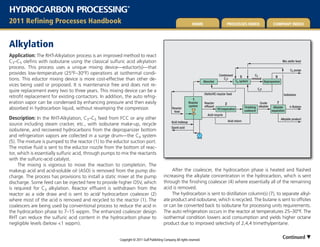
- 1. HYDROCARBON PROCESSING ® 2011 refining Processes Handbook Home Processes Index comPany Index alkylation Application: The RHT-Alkylation process is an improved method to react C3–C5 olefins with isobutane using the classical sulfuric acid alkylation Mix olefin feed process. This process uses a unique mixing device—eductor(s)—that C3 purge provides low-temperature (25°F–30°F) operations at isothermal condi- Condensed C3 5 6 tions. This eductor mixing device is more cost-effective than other de- Absorber C4s C4 system removal Depropanizer vices being used or proposed. It is maintenance free and does not re- C4s quire replacement every two to three years. This mixing device can be a Olefin/HC reactor feed Isobutane retrofit replacement for existing contactors. In addition, the auto refrig- 1 eration vapor can be condensed by enhancing pressure and then easily Reactor Reactor 2 Crude 7 system effluent Finishing alkylate Alkylate n-Butane absorbed in hydrocarbon liquid, without revamping the compressor. Reactor HC/separation coalescer separation feed Acid recycle Description: In the RHT-Alkylation, C3–C5 feed from FCC or any other Acid return Alkylate product Acid makeup source including steam cracker, etc., with isobutane make-up, recycle Spent acid isobutene, and recovered hydrocarbons from the depropanizer bottom and refrigeration vapors are collected in a surge drum—the C4 system (5). The mixture is pumped to the reactor (1) to the eductor suction port. The motive fluid is sent to the eductor nozzle from the bottom of reac- tor, which is essentially sulfuric acid, through pumps to mix the reactants with the sulfuric-acid catalyst. The mixing is vigorous to move the reaction to completion. The makeup acid and acid-soluble oil (ASO) is removed from the pump dis- After the coalescer, the hydrocarbon phase is heated and flashed charge. The process has provisions to install a static mixer at the pump increasing the alkylate concentration in the hydrocarbon, which is sent discharge. Some feed can be injected here to provide higher OSV, which through the finishing coalescer (4) where essentially all of the remaining is required for C3 alkylation. Reactor effluent is withdrawn from the acid is removed. reactor as a side draw and is sent to acid/ hydrocarbon coalescer (2) The hydrocarbon is sent to distillation column(s) (7), to separate alkyl- where most of the acid is removed and recycled to the reactor (1). The ate product and isobutane, which is recycled. The butane is sent to offsites coalescers are being used by conventional process to reduce the acid in or can be converted back to isobutane for processing units requirements. the hydrocarbon phase to 7–15 wppm. The enhanced coalescer design The auto refrigeration occurs in the reactor at temperatures 25–30°F. The RHT can reduce the sulfuric acid content in the hydrocarbon phase to isothermal condition lowers acid consumption and yields higher octane negligible levels (below <1 wppm). product due to improved selectivity of 2,4,4 trimethylpentane. Copyright © 2011 Gulf Publishing Company. All rights reserved. Continued
- 2. Alkylation, continued The auto-refrigeration vapor is first enhanced by the ejector and then absorbed in a heavy liquid—alkylate, which provides a low-cost option and then condensed. Some liquid is sent to depropanizer (6); propane and light ends are removed. The bottoms are recycled to C4 system and sent to the reactor. The major advances of RHT process are threefold: eductor mixing device, advance coalescer system to remove acid from hydrocarbon (dry system), and C4 autorefrigeration vapors recovery by absorption, mak- ing compressor redundant. Economics: For a US Gulf Coast unit 1Q 2006 with a capacity of 10,000 bpd alkylate unit CAPEX ISBL, MM USD 29.5 Power, kWh 2,800 Water, cooling, m3/ h 1,750 Steam, kg / h 25,600 FCC Feed (about 15% isobutelene in C4 mixed stream) Product properties: Octane (R+M)/2:94.8–95.4 Commercial units: Technology is ready for commercialization. References: US patent 5,095168. US Patent 4,130593. Kranz, K., “Alkylation Chemistry,” Stratco, Inc., 2001. Branzaru, J., “Introduction to Sulfuric Acid Alkylation,” Stratco, Inc., 2001. Nelson, Handbook of Refining. Meyers, R. A., Handbook of Refining, McGraw Hill, New York, 1997. Licensor: Refining Hydrocarbon Technologies LLC contact
- 3. HYDROCARBON PROCESSING ® 2011 refining Processes Handbook Home Processes Index comPany Index Biodiesel Esterification Transesterification reactor reactor Application: The RHT- Biodiesel process is optimized to produce biodiesel Triglycerides from palm oil, rape-seed oil, vegetable and animal products that contain LP fatty acids with even number of carbon atom (12 to 22). The lack of Methanol Biodiesel sulfur in the biodiesel enables complying with many international fuel Biodiesel product Purification specifications. Mixer The biodiesel is comparable to petroleum-based diesel. Triglycerides Gravity Water wash separator are reacted with methanol, ethanol or higher alcohols to yield biodiesel MeOH/water for recovery Water within the acceptable boiling range. Methanol is most commonly used for the biodiesel production since it is the most cost-effective of alco- MeOH/water for recovery hols, and it can provide better economics for the biodiesel producers. Purification Biodiesel is produced by reacting vegetable oils and animal fats (triglyc- Glycerine product erides) with methanol in the presence of highly alkaline heterogeneous Esterification Transesterification catalyst at moderate pressure and temperature. Pretreatment may be reactor reactors Wash solvent Triglycerides required if the vegetable oil has a high free-fatty acids content to LP optimize methyl esters yield. If free fatty acids are present in the Residual glycerine/wash solvent feed, first step is esterfication of the free-fatty acid with metha- Methanol Biodiesel nol. However if the free-fatty acids concentrations are low, then Biodiesel product this step can be deleted. Mixer Gravity The triglycerides and methanol are converted by transesterfication separator Water wash reaction to yield methyl esters of the oils and fats, and glycerine is pro- Water MeOH/water for recovery duced as a byproduct. The glycerine is separated from the methyl esters MeOH/water for recovery (biodiesel) by phase separation via gravity settling. The methyl esters and glycerine are purified to meet the product specifications. Purification Glycerine product Description: In the simplified process flow diagram (1), the feed—veg- etable oil or animal fats—is pumped from storage and is mixed with methanol in the required molar ratio vegetable/methanol at moderate operating pressure. The feed is heated to the reaction temperature and the vegetable oils. (Note: the pretreatment is only required when the is sent to esterification reactor. Free-fatty acids are pretreated if the con- feed contains free-fatty acids; otherwise, this step can be omitted. centration exceeds 3% percent of the feed. The reactor contains an acid The effluent from the first reactor (if free-fatty acids are present) or catalyst for this reaction and can remove 99.9 % of free-fatty acids from the heated feed is sent to the transesterfication reactor, where 3 moles Copyright © 2011 Gulf Publishing Company. All rights reserved. Continued
- 4. Biodiesel, continued Economics: The normal utilities for continuous biodiesel unit based on heterogeneous catalyst for tph of biodiesel capacity are listed. This does of methanol react with the triglyceride to produce 3 moles of methyl not include the glycerine purification utilities. The capital cost for the ester oil (biodiesel) and one mole of glycerine. The transesterfication re- ISBL Biodiesel plant on Gulf coast site basis based on 1Q 2006 is pro- actor uses a highly alkaline heterogeneous catalyst and provides essen- vided below. tially 100% conversion. The transesterification reactor effluent is sent CAPEX ISBL plant: USD/ton Biodiesel 235–265 to gravity separator/settler. The biodiesel product is taken from the top Steam, lb/h 368 of the separator, and is water washed. The washed biodiesel product is Water, cooling gpm 64 taken from the top of the drum. Water washing removes excess metha- Power, kWh 9 nol from the reaction products, which is recovered by normal distillation; the pure methanol is recycled back to the reactor. The bottoms from the Licensor: Refining Hydrocarbon Technologies LLC contact separator/settler are sent to the purification unit to remove impurities and residual methanol, which is recycled back. Pure glycerine product is sent to storage. Fig. 2 is an alternate flow scheme; a spare transesterification reactor is added to remove glycerine from the reactor to sustain reaction rates. Once the reaction rates are reduced the reactor is switched and washed with hot solvent to remove residual glycerine and biodiesel. This extra reactor patented mode of operation provides higher reactions rates and onstream capability while enhancing yield and productivity. Glycerine purity can exceed 99.8% after distillation. Reaction chemistry: Transesterification reactions: Triglycerides + 3 Methanol ➞ Methyl Ester of the oil (biodiesel) + Glycerol Comparision of the Diesel/Biodiesel Properties Fuel Property Diesel Biodiesel Fuel standard ASTM D 975 ASTM P S 121 Fuel composition C10–C21 HC C12–C22 FAME Lower heating value, Btu/gal 131 117 Kinemetic Vis @ 40°C 1.3–4.1 1.9–6 SG at 60°F 0.85 0.88 Water, wppm 161 500 Carbon 87 77 Hydrogen 13 12 Oxygen 0 11 Sulfur, wppm 15–500 0 Bp, °F 380–650 370–340 Flash Pt, °F 140–175 210–140
- 5. HYDROCARBON PROCESSING ® 2011 refining Processes Handbook Home Processes Index comPany Index Hydrogenation/ Low pressure splitter H2 recycle/vent hydrodesulfurization Hydrocarbons reformate1 (A) LP Light hydrocarbons Application: The smart configuration can be applied for selec- Hydrogen recycle2 tive hydrogenation/hydroisomerization, aromatic saturation and H2 Hydrogenation hydrodesulfurization (HDS) of gasoline, kerosine and diesel/distillate reactor desulfurization. In addition, this process can be used for the selective hydrogenation of acetylene, MAPD, C3 /C4 /C5 /C6 /C7 and LCN, hydro- isomerization, benzene saturation and hydrodesulfurization of gasoline, 1 Hydrocarbons from refinery/petrochemical and other units kerosine and diesel/distillate. Multiple catalyst types provide the best 2 If recycle is required for excess hydrogen Heavy hydrocarbons performance and lower cost with optimum configuration. The RHT pro- cess operates the distillation and reaction units at optimum conditions SHU reactor Gasoline stripper 5 HDS Compressor reactor H2 recycle/vent and integrates the stabilizer with the main distillation column thereby FCC naphtha Mixer reducing CAPEX and OPEX. By taking multiple draws off from distillation L cat naphtha (B) column, it is possible to obtain the highest conversion, high selectivity H2 H2 Recycle Compressor Vent Mid cut with low operating costs. The processes apply optimum catalyst and Recycle H2 naphtha conditions to obtain the best results. The process is optimized for energy Makeup consumption via heat integration to provide low CAPEX and OPEX. Flash H2 drum Description: Flash RHT-Hydrogenation: In the RHT- Hydrogenation process (flow dia- drum gram A), the hydrocarbon feed is sent to the distillation column where the feed is treated and taken as a side draw or multiple draw offs. The H2 to furnace Furnace feed can be treated in an optimum way for catalyst/reactor utilization. Additional liquid is needed to dilute the feed and to maintain reaction temperature. The feed is mixed with sufficient hydrogen to maintain the required for reaction before entering the reactor. The side draw is mixed The process uses metal catalyst used for hydrogenation. Most com- with liquid from the heat sink and is heated to the reactor temperature. monly used catalysts are Pt/Pd, Pd/Ag, Pd, Ni, Ni/Mo, and Co/Mo on The reactor effluent is sent back to the distillation column to remove silica or alumina base. (Catalysts such as zeolite/Pt can be used aromatic light ends/hydrogen at top, and the product is taken as side draw after saturation). The process can be optimized for multiple or single cata- the pasteurization section. The bottom product does not require further lyst to provide best catalyst utilization and lower cost. The multiple side treatment except in the isomerization option. draws allows heat sink and highest conversions and selectivity required Copyright © 2011 Gulf Publishing Company. All rights reserved. Continued
- 6. Hydrogenation/hydrodesulfurization, continued The catalyst used for first reactor for selective hydrogenations are Pt/ Pd, Pd, Ni, Ni//W or Ni/Mo depending upon the feed and operating con- for the process/olefins or saturation. The process uses lower pressure ditions selected. Catalyst required for HDS include Co/ Mo, Ni/W or Ni/ than conventional processes and can work in single phase or two phase Mo. RHT processes do not use any internals. Additionally, if the capacity reactor operation. must be increased for future processes with special internals become a RHT-HDS: FCC Gasoline: The RHT- HDS process (flow diagram B) bottleneck and one has to install complete additional train, which is very can be used for FCC gasoline. Processing scheme for straight-run naph- expensive. tha, heavy gasoil and diesel is similar to conventional schemes. The FCC RHT-HDS: Gasoil/diesel: RHT has a configuration to desulfurize the gasoline is mixed with hydrogen and is heated to moderate tempera- crude and vacuum unit pumparound and main fractionators side draws ture. The feed is sent to the selective hydrogenation reactor to remove at the location with staggered pressures so that hydrogen can be spilled diolefins to prevent the formation of gums and polymers and coking into lower pressure unit, gasoil, diesel/kerosine/naphtha in that order. on the HDS catalyst. The reactor operates in two phases or single phase The flow schemes are similar to conventional processes with reactor down-flow reaction mode. Reactor effluent is sent to the splitter where internals designed to meet high-distribution efficiency. The catalyst is light cut naphtha (LCN) is taken as side-draw overhead and heavy cut same as mentioned above earlier, e.g., Co/Mo, Ni/W, Ni/Mo. Zeolite/Pt naphtha (HCN) is taken from the bottom and medium cut naphtha catalyst and Ni is used for light cycle oil (LCO) aromatic saturation and (MCN) is taken as side draw. The LCN is almost sulfur-free and contains ring opening. less than 3 to 5 wppm mercaptans and other sulfur compounds. DMS is essentially eliminated or minimized. Economics: 1Q 2006 Gulf coast Basis; The HCN is taken from bottom of the splitter and is mixed with RHT-Hydrogenation: hydrogen required for HDS and is heated to the desulfurization tem- CAPEX (ISBL facility only), $/bbl 517 perature in the furnace. The feed is fed to the HDS reactor in down- Utilities and catalyst, $/bbl 0.25 flow mode. The HDS occurs in the catalyst zone at high temperatures RHT-HDS: to support high desulfurization rates HCN, which contains the maxi- Capex (ISBL facility only), $/bbl 980 mum sulfur level and is the most refractory. The MCN is also mixed with Utilities and catalyst, $/bbl 1.26 hydrogen and heated to the reactor temperature and is sent the HDS reactor around the middle of reactor. The space velocity for HCN and Product properties: Hydrogenation stream meets the diolefin specifica- tion as required with high selectivity. For HDS, the product sulfur speci- MCN depends on the total sulfur concentration in both streams and the fications are met below 10 wppm. sulfur-containing species. Another consideration for the catalyst quan- tity is based on the product specifications required. The reactor effluent Installation: Technology is ready for commercialization. is sent to stabilizer, where residual sulfur is driven from the MCN and HCN product and is taken as the bottom product from stabilizer. Licensor: Refining Hydrocarbon Technologies LLC.
- 7. HYDROCARBON PROCESSING ® 2011 refining Processes Handbook Home Processes Index comPany Index Isooctene/isooctane Water wash Mixer 1st Debutanizer Finishing Isooctene column reactor reactor column C raffinate Application: New processes, RHT-isooctene and RHT-isooctane, can 5 4 be used to revamp existing MTBE units to isooctene/isooctane produc- 3 12 Selectivator recycle IPA LP tion. Feeds include C4 iso-olefin feed from FCC, steam crackers, thermal Water wash H2 7 crackers or on-purpose iso-butylene from dehydrogenation units. The 2 9 13 processes uses a unique configuration for dimerization. A new selectiva- 10 11 tor is used, together with a dual-bed catalyst. 8 4 C4 feed (1) The configuration is capable of revamping conventional or reactive 1 14 distillation MTBE units. The process provides higher conversion, better Water to treatment (1) 1 Isooctene product selectivity, conventional catalyst, and a new selectivator supports with to 3% propylene in feed 6 longer catalyst life with a dual catalyst application. Isooctene Mixer 1st reactor KO drum CW Isooctene stripper The process is designed to apply a hydrogenation unit to convert 5 7 Vent 11 isooctene into isooctane, if desired, by utilizing a dual-catalyst system, 6 in the first and finishing reactors. The process operates at lower pressure H2 1 6 Finishing and provides lower costs for the hydrogenation unit. reactor 4 9 Description: The feed is water washed to remove any basic compounds that can poison the catalyst system. Most applications will be directed 3 toward isooctene production. However as olefin specifications are re- 10 Hydrogen 6 Isooctene product quired, the isooctene can be hydrogenated to isooctane, which is an excellent gasoline blending stock. The RHT isooctene process has a unique configuration; it is flexible and can provide low per pass conversion through dilution, using a new resin catalyst via a side reactor. The feed to the side reactor is taken as selectivator. The dual catalyst system also provides multiple advantages. a side draw from the column and does contain unreacted isobutylene, The isobutylene conversion is 97–99 %, with better selectivity and yield selectivator, normal olefins and non-reactive C4s. The recycle stream together with enhanced catalyst life. The product is over 91% C8 olefins, provides the dilution, and reactor effluent is fed to the column at mul- and 5 – 9% C12 olefins, with very small amount of C16 olefins. tiple locations. Recycling does not increase column size due to the The feed after water wash, is mixed with recycle stream, which unique configuration of the process. The isooctene is taken from the provides the dilution (also some unreacted isobutylene) and is mixed debutanizer column bottom and is sent to OSBL after cooling or as is with a small amount of hydrogen. The feed is sent to the dual-bed re- sent to hydrogenation unit. The C4s are taken as overhead stream and actor for isooctene reaction in which most of isobutylene is converted sent to OSBL or alkylation unit. Isooctene/product, octane (R+M)/2 is to isooctene and codimer. The residual conversion is done with single- expected to be about 105. Copyright © 2011 Gulf Publishing Company. All rights reserved. Continued
- 8. Isooctene/isooctane, continued If isooctane is to be produced the debutanizer bottom, isooctene product is sent to hydrogenation unit. The isooctene is pumped to the required pressure (which is much lower than conventional processes), mixed with recycle stream and hydrogen and is heated to the reaction temperature before sending it the first hydrogenation reactor. This reac- tor uses a nickel (Ni) or palladium (Pd) catalyst. If feed is coming directly from the isooctene unit, only a start-up heater is required. The reactor effluent is flashed, and the vent is sent to OSBL. The liquid stream is recycled to the reactor after cooling (to remove heat of reaction) and a portion is forwarded to the finishing reactor—which also applies a Ni or Pd catalyst (preferably Pd catalyst) — and residual hydrogenation to isooctane reaction occurs. The isooctane product, octane (R+M)/2 is >98. The reaction occurs in liquid phase or two phase (preferably two phases), which results in lower pressure option. The olefins in isooctene product are hydrogenated to over 99%. The finishing reactor effluent is sent to isooctane stripper, which removes all light ends, and the product is stabilized and can be stored easily. Economics: Isooctene Isooctane1 CAPEX ISBL, MM USD (US Gulf Coast 1Q 06, 1,000 bpd) 8.15 5.5 Utilities basis 1,000-bpd isooctene/isooctane Power, kWh 65 105 Water, cooling, m 3/h 154 243 Steam, HP, kg/h 3,870 4,650 Basis: FCC feed (about 15–20% isobutelene in C4 mixed stream) 1These utilities are for isooctene / isooctane cumulative. Installation: Technology is ready for commercial application. Licensor: Refining Hydrocarbon Technologies LLC ContACt
- 9. HYDROCARBON PROCESSING ® 2011 refining Processes Handbook Home Processes Index comPany Index olefin etherification Application: New processing methods improve etherification of C4– C7 Water Wash column 1st Fractionator Condenser Finishing Alcohol Alcohol recovery trayed or packed reactor reactor extraction column reactive olefins including light catalytic naphtha (LCN) with alcohol (e.g., methanol and ethanol). The processes, RHT-MixedEthers, RHT-MTBE, Alcohol MeOH or ETOH C4 or C5 raffinate OSBL Water RHT-ETBE, RHT-TAME and RHT-TAEE, use unique concepts to achieve the Alcohol recycle LPS purge C4 or C5/C7 maximum conversion without applying cumbersome catalyst in the col- CW CW umn. The processing economics provide improvements over other avail- Wash water 2 CW 7 Alcohol 3 able ether technologies currently available. The technology suite can C4 feed or 1 CW recycle to reactor be applied to ethyl tertiary butyl ether (ETBE) production in which wet C5-C7* 5 6 ethanol can be used in place of dry ethanol. The drier can be eliminated, MPS 4 C4 or C5 Water raffinate** LP which is approximately half the cost for an etherification unit. The RHT ethers processes can provide the highest conversion with unique mul- MTBE/ETBE or mixed Alcohol ether product Water makeup tiple equilibrium stages. * No recycle reactor required. **only C5s Description: The feed is water washed to remove basic compounds that are poisons for the resin catalyst of the etherification reaction. The C4 ethers—methyl tertiary butyl ether (MTBE)/ETBE), C5 – tertiary amyl methyl ether (TAME/ tertiary amyl ethyl ether (TAEE) and C6 /C7 ethers are made in this process separately. The reaction is difficult; heavier Major vaporization is detrimental to this reaction. Vapor-phase re- ethers conversion of the reactive olefins are equilibrium conversion of active olefins are not available for reaction. Additionally at higher tem- about 97% for MTBE and 70% for TAME and much lower for C6 /C7 peratures, there is slight thermal degradation of the catalyst occurs. The ethers are expected. reactor effluent is sent to fractionator (debutanizer or depentanizer) to Higher alcohols have similar effects (azeotrope hydrocarbon/alcohol separate the ether and heavy hydrocarbons from C4 or C5 hydrocar- relationship decreases when using methanol over ethanol). The equilib- bons, which are taken as overhead. Single or multiple draw offs are rium conversions and azeotrope effects for higher ethers are lower, as is taken from the fractionation column. In the fractionation column, unre- expected. After the hydrocarbon feed is washed, it is mixed with alcohol acted olefins (C4 or C5) are sent to the finishing reactor (5). This stream with reactive olefin ratio control with alcohol. normally does not require alcohol, since azeotrope levels are available. The feed mixture is heated to reaction temperature (and mixed with But, some additional alcohol is added for the equilibrium-stage reaction. recycle stream (for MTBE/ETBE only) and is sent to the first reactor (1), Depending on the liquid withdrawn (number of side draws), the conver- where equilibrium conversion is done in the presence of sulfonated resin sion can be enhanced to a higher level than via other conventional or catalyst, e.g. Amberlyst 15 or 35 or equivalent from other vendors. unconventional processes. Copyright © 2011 Gulf Publishing Company. All rights reserved. Continued
- 10. Olefin etherification, continued Economics: CAPEX ISBL, MM USD (US Gulf Coast 1Q06, By installing multiple reactors, it is possible to extinct the olefins 1,000-bpd ether product) 9.1 within the raffinate. The cost of side draws and reactors can achieve Utilities Basis 1,000 bpd ether pay-off in 6 to 18 months by the higher catalyst cost as compared to Power kWh 45.0 Water, cooling m 3/ h 250 other processes. This process could provide 97–99.9% isobutene con- version in C4 feed (depending on the configuration) and 95–98+% of Steam MP, Kg / h 6,000 isoamylenes in C5 stream. Basis: FCC Feed (about 15–20% isobutylene in C4 mixed stream) The ether product is taken from the bottom, cooled and sent to the storage. The raffinate is washed in extractor column (6) with and is sent Commercial units: Technology is ready for commercialization. to the OSBL. The water/alcohol mixture is sent to alcohol recovery col- Licensor: Refining Hydrocarbon Technologies LLC contact umn (7) where the alcohol is recovered and recycled as feed. For ETBE and TAEE, ethanol dehydration is required for most of the processes, whereas for RHT process, wet ethanol can be used providing maximum conversions. If need be, the TBA specification can be met by optimum design with additional equipment providing high ETBE yield and conversion. Cost of ethanol dehydration is much more than the present configuration for the RHT wet-ethanol process. The total capital cost /economics is lower with conventional catalyst usage, compared to other technologies, which use complicated struc- ture, require installing a manway (cumbersome) and require frequently catalyst changes outs. The RHT ether processes can provide maximum conversion as com- pared to other technologies with better economics. No complicated or proprietary internals for the column including single source expensive catalyst. Distillation is done at optimum conditions. Much lower steam consumption for alcohol recovery. For example, the C5 feed case requires less alcohol with RHT configuration (azeotropic alcohol is not required) and lowers lower steam consumption.