
Recommended
Recommended
More Related Content
What's hot
What's hot (20)
Viewers also liked
Viewers also liked (20)
Similar to Moving target indicator radar (mti)part2
Similar to Moving target indicator radar (mti)part2 (20)
Recently uploaded
Recently uploaded (20)
Moving target indicator radar (mti)part2
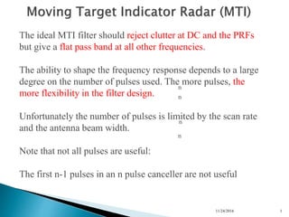
- 1. 11/24/2016 1 n n n n The ideal MTI filter should reject clutter at DC and the PRFs but give a flat pass band at all other frequencies. The ability to shape the frequency response depends to a large degree on the number of pulses used. The more pulses, the more flexibility in the filter design. Unfortunately the number of pulses is limited by the scan rate and the antenna beam width. Note that not all pulses are useful: The first n-1 pulses in an n pulse canceller are not useful
- 2. 11/24/2016 2 n n n n Some other transversal filter responses are shown: (1) 3 pulse canceler (2) 5 pulse “optimum” filter which maximizes IC (3) 15 pulse Chebyshev filter
- 3. 11/24/2016 3 Moving Target Indicator Radar (MTI) Feed forward (finite impulse response or FIR) filters have only poles (one per delay) More flexibility in filter design can be obtained if we use recursive or feedback filters (also known as infinite impulse response or IIR filters) These have a zero as well as a pole per delay and thus have twice as many variables to play with
- 4. 11/24/2016 4 Moving Target Indicator Radar (MTI) IIR filters can be designed using standard continuous-time filter techniques and then transformed into the discrete form using z transforms Thus almost any kind of frequency response can be obtained with these filters. They work very well in the steady state case but unfortunately their transient response is not very good. A large pulse input can cause the filter to “ring” and thus miss desired targets. Since most radars use short pulses, the filters are almost always in a transient state
- 5. 11/24/2016 5 Moving Target Indicator Radar (MTI) Multiple PRFs An alternative is to use multiple PRFs because the blind speeds (and hence the shape of the filter response) depends on the PRF and, combining two or more PRFs offers an opportunity to shape the overall response.
- 6. 11/24/2016 6 Moving Target Indicator Radar (MTI) Digital (or Discrete) Signal Processing (DSP) These days almost all radar signal processing is done using DSP. The down-converted signal is sampled by an A/D converter as follows: Note: The quadrature channel removes blind phases
- 7. 11/24/2016 7 Moving Target Indicator Radar (MTI) •Advantages of DSP •greater stability •greater repeatability •greater precision •greater reliability •easy to implement multiple PRFs •greater flexibility in designing filters •gives the ability to change the system parameters dynamically
- 8. 11/24/2016 8 Moving Target Indicator Radar (MTI) Digital (or Discrete) Signal Processing (DSP) Note that the requirements for the A/D are not very difficult to meet with today’s technology. Sampling Rate Assuming a resolution (Rres) of 150m, the received signal has to be sampled at intervals of c/2Rres = 1μs or a sampling rate of 1 MHz Memory Requirement Assuming an antenna rotation period of 12 s (5rpm) the storage required would be only 12 Mbytes/scan.
- 9. 11/24/2016 9 Moving Target Indicator Radar (MTI) Digital (or Discrete) Signal Processing (DSP) Quantization Noise The A/D introduces noise because it quantizes the signal The Improvement Factor can be limited by the quantization noise the limit being: 75.0)12(log20 N QNI This is approximately 6 dB per bit A 10 bit A/D thus gives a limit of 60 dB In practice one or more extra bits to achieve the desired performance
- 10. 11/24/2016 10 Moving Target Indicator Radar (MTI) Digital (or Discrete) Signal Processing (DSP) Dynamic Range This is the maximum signal to noise ratio that can be handled by the A/D without saturation 232 /2_ krangedynamic N N= number of bits k=rms noise level divided by the quantization interval the larger k the lower the dynamic range but k<1 results in reduction of sensitivity Note: A 10 bit A/D gives a dynamic range of 45.2dB
- 11. 11/24/2016 11 Moving Target Indicator Radar (MTI) Blind Phases If the prf is double the Doppler frequency then every other pair of samples can be the same amplitude and will thus be filtered out of the signal. (loss of 2.8dB and 13.7dB for Pd of 0.5 and 0.9 respectively) By using both inphase and quadrature signals, blind phases can be eliminated
- 12. 11/24/2016 12 w w w w w w w w SUMMER z-1 z-1 z-1 z-1z-1 z-1 z-1 z-1 Moving Target Indicator Radar (MTI) Digital Filter Banks and FFT Example: Transversal Filter with 8 delay elements: If the weights are set to: Nkij ik ew /)1(2 i= 1,2,3…N and k is an index from 0 to N-1
- 13. 11/24/2016 13 Moving Target Indicator Radar (MTI) The impulse response of this filter is: NkijN ik eTitth /)1(2 1 )1()( And from the Fourier transform its frequency response is N i NkfTijfTj k eefH 1 /)1(22 )( The magnitude of the response is NkfT NkfTN fHk /(sin /(sin )(
- 14. 11/24/2016 14 Moving Target Indicator Radar (MTI) NkfT NkfTN fHk /(sin /(sin )( k=0 0 1/T 0 1/T k=1
- 15. 11/24/2016 15 Moving Target Indicator Radar (MTI) MTD (Moving Target Detector) Example: ASR (Airport`Surveillance Radar) Range: 60 NM Antenna Rotation: 12.5 - 15rpm Frequency:2.7 - 2.9 GHz fp: 700 - 1200 Hz Beamwidth: 1.4º Uses a 3 pulse canceller with an 8 pulse doppler filter bank Measured IC = 45dB A/D converter uses 10 bits
- 16. 11/24/2016 16 Moving Target Indicator Radar (MTI) MTD (Moving Target Detector) Example: ASR (Airport`Surveillance Radar) 47.5 NM of range (22.5NM - 60NM) divided into 1/16 NM intervals ( approximately 120m) 760 range bins Azimuth is divided into 0.75º intervals (approximately 1/2 beamwidth) 480 azimuth bins The eight doppler filters give 8 Doppler bins for a total of 2,918,00 range/azimuth/doppler cells each cell has its own adaptive threshold level
- 17. 11/24/2016 17 Moving Target Indicator Radar (MTI) MTD (Moving Target Detector) Example: ASR (Airport`Surveillance Radar) 10 Pulses at one PRF is transmitted for 0.75º of azimuth and 10 pulses at the other PRF for the next 0.75º. This eliminates second time around clutter
- 18. 11/24/2016 18 Moving Target Indicator Radar (MTI) MTD (Moving Target Detector) Example: ASR (Airport`Surveillance Radar)
- 19. 11/24/2016 19 Moving Target Indicator Radar (MTI) MTD (Moving Target Detector) Example: ASR (Airport`Surveillance Radar) After the filter bank the doppler filter outputs are weighted to reduce the effects of the sidelobes in the filter The outputs of the filters are modified by subtracting 25% of the outputs of the filters on either side.
- 20. 11/24/2016 20 Moving Target Indicator Radar (MTI) MTD (Moving Target Detector) Example: ASR (Airport`Surveillance Radar)