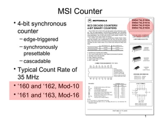
SlideShare a Scribd company logo
1 of 35
MSI Counter
• 4-bit synchronous
  counter
  – edge-triggered
  – synchronously
    presettable
  – cascadable
• Typical Count Rate of
  35 MHz
• ‘160 and ‘162, Mod-10
• ‘161 and ‘163, Mod-16


                               1
MSI Counter
• 74LS163 4-bit synchronous counter


                                      16-pin DIP


                                                   2
MSI Counter
• 74LS163 characteristics
  – edge-triggered
  – synchronously presettable
  – cascadable
  – count modulo 16 (binary)        74x163
• Synchronous Reset
  (Clear) input that overrides
  all other control inputs
  – active only during the rising
    clock edge


                                             3
MSI Counter
• 74LS163 logic symbols

                      datasheet

         text
                                  74x163


                                           4
MSI Counter
• 74LS163 state diagram and logic equations


                                              5
MSI Counter
• 74LS163 mode select table
• All signals must be high ( H ) to enable the
  count sequence to begin


                                                 6
MSI Counter
• 74x163 is a synchronous
  4-bit binary counter
• RCO=1 when all count
  bits are 1 and ENT is
  asserted


                                  7
MSI Counter
 • The control inputs for the 74x163 have the
   following effects:


clear
 load
 hold
hold


                                                8
74x163
Internal Logic
   Diagram
Counter Operation
• Free-running ÷16
• Count if ENP and
  ENT both asserted
• Load if LD is asserted
  (overrides counting)
• Clear if CLR is asserted
  (overrides loading and
  counting)
• All operations take place on
  rising CLK edge
                                 makes it free-running
• RCO is asserted if ENT is
  asserted and
  Count = 15
                                                         10
Free-Running 4-Bit ’163 Counter
• “divide-by-16” counter
• RCO is asserted if ENT is asserted and Count = 15


                                                      11
Modified Counting Sequence


       DCBA
• Load 0101 (5) after Count = 15
• 5, 6, 7, 8, 9, 10, 11, 12, 13, 14, 15, 5, 6, …
• “divide-by-11” counter
                                                   12
Another Way


• Clear after Count = 1010 (10)
• 0, 1, 2, 3, 4, 5, 6, 7, 8, 9, 10, 0, 1, 2, 3, …
• “modulo-11” or “divide-by-11” counter
                                                    13
Counting
from 3 to 12


               14
Cascading Counters
• For modulus greater than 16
• RCO (ripple carry out) is asserted in state 15, if ENT is asserted


                                                              15
Decoding Binary-Counter States
• A binary counter may be combined with a decoder to obtain a set of
  1-out-of-m coded signals, where one signal is asserted in each
  counter state
 Useful when counter outputs are used to control a set of devices
 A different device is enabled in each counter state
 In this approach each output of the decoder enables a different device
 The next slide shows the 74163 wired as a modulo 8 counter
   combined with a 74138 (3 to 8 decoder)
 The decoder output provides eight signals, each one representing a
   counter state


                                                                  16
Decoding Binary-Counter States


                                 17
Decoding Binary-Counter States
• The next slide shows a typical timing diagram for this
  circuit
• Each decoder output is asserted during a corresponding
  clock period
• The decoder outputs may contain “glitches” on state
  transitions where two or more counter bits change
• This happens even though the 74163 outputs are glitch free
  and the 74138 does not have any static hazards
• In a synchronous counter like the 74163 the outputs don’t
  change exactly at the same time
• Moreover multiple signal paths in a decoder like 74138
  have different delays; thus the output may have glitches
• This problem is an example of functional hazard


                                                           18
Decoder Waveforms
• Glitches may or may not be a concern


                                         19
Glitch-Free Outputs
• In most applications these would be used as control inputs to
  counters, registers and other edge triggered devices
• In such a case there is no problem as the glitches occur after
  the clock tick
• They would be a problem if applied to latches
• They would also be a problem if utilized as a clock
• One way to “clean-up” these glitches is to connect the 74138
  decoder output to another register
• This register would sample the stable decoded outputs on the
  next clock tick as shown in the next slide
• In this case the final outputs would have to be renamed to
  account for the one clock tick delay through the register

                                                             20
Glitch-Free Outputs


• Register outputs delayed by one clock cycle


                                                21
74161 MSI Counter
• The 74163 is fully synchronous
• Some applications require an asynchronous
  clear function
• That is provided by 74161
• It has the same pinout as 74163
• Its CLR_L input is connected to the
  asynchronous clear inputs of its flip flops
Modulo-10 Counters
• From the 74LS163 “family” – the 74LS160
  – 74LS160 in free-running mode
  – Duty cycle of QC and QD is not 50%


                                            23
Modulo-10 Counters
• 74LS160 state diagram
• The 74LS160 (and
  74LS162) can be preset
  to any state, but will not
  count beyond 9.
• If preset to state 10, 11,
  12, 13, 14, or 15, it will
  return to its normal
  sequence within two clock
  pulses.
• 74160 has asynchronous
  clear as in 74161
                                24
Up/Down Counters
• A 3-bit binary up/down counter (block diagram)

                             QA
     Clock                   QB
                  Counter              Count
                             QC


                 UP / DOWN


                                               25
Up/Down Counters
• A 3-bit binary up/down counter (State diagram)


                                              26
Up/Down Counters


                   27
Up/Down Counters
• This circuit is a 3-bit UP/DOWN synchronous counter using
  JK flip-flops configured to operate as toggle or T-type flip-
  flops giving a count of zero (000) to seven (111) and back to
  zero again.
• An additional input determines the direction of the count,
  either UP or DOWN and the timing diagram gives an
  example of the counters operation as this UP/DOWN input
  changes state.


                                                             28
Timing diagram
Up/Down Counters
• The 74LS169 is a fully
  synchronous 4-stage
  up/down counter
• Includes:
  – a preset capability for
    programmable
    operation
  – carry lookahead for
    easy cascading
  – a U/ D input to control
    the direction of
    counting

                                 30
Up/Down Counters
• The SN74LS169 operates in a Modulo-16
  binary sequence


                                          31
74LS169 logic circuit diagram
Up/Down Counters
• 74LS169 logic symbol
                 • Functions similar to 74163
                 • Difference is that its carry output
                   and enable inputs are active low
                 • It is an up/down counter
                 • It counts ascending or descending
                   binary order depending on the value
                   of input signal UP/DN
                 • Counts up when UP/DN is 1
                 • Counts down when UP/DN is 0


                                                 33
MSI Counters
•   7458: Dual 4-bit Decade Counter                                              •   74454: Dual Decade Up/Down Counter, Synchronous, Preset Input
•   7459: Dual 4-bit Binary Counter                                              •   74455: Dual Binary Up/Down Counter, Synchronous, Preset Input
•   7468: Dual 4 Bit Decade or Binary Counters                                   •   74461: 8-bit Presettable Binary Counter with three-state outputs
•   7469: Dual 4 Bit Decade or Binary Counters                                   •   74490: Dual Decade Counter
•   7490: Decade Counter (separate Divide-by-2 and Divide-by-5 sections)         •   74491: 10-bit Binary Up/Down Counter with Limited Preset and three-state
•   7492: Divide-by-12 Counter (separate Divide-by-2 and Divide-by-6                 logic outputs
    sections)                                                                    •   74560: 4-bit Decade Counter with three-state outputs
•   7493: 4-bit Binary Counter (separate Divide-by-2 and Divide-by-8 sections)   •   74561: 4-bit Binary Counter with three-state outputs
•   74142: Decade Counter/Latch/Decoder/Nixie Tube Driver                        •   74568: Decade Up/Down Counter with three-state outputs
•   74143: Decade Counter/Latch/Decoder/7-segment Driver, 15 mA Constant         •   74569: Binary Up/Down Counter with three-state outputs
    Current                                                                      •   74590: 8-Bit Binary Counter with Output Registers and three-state outputs
•   74144: Decade Counter/Latch/Decoder/7-segment Driver, 15V open               •   74592: 8-Bit Binary Counter with Input Registers
    collector outputs                                                            •   74593: 8-Bit Binary Counter with Input Registers and three-state outputs
•   74160: Synchronous 4-bit Decade Counter with Asynchronous Clear              •   74668: Synchronous 4-bit Decade Up/Down Counter
•   74161: Synchronous 4-bit Binary Counter with Asynchronous Clear              •   74669: Synchronous 4-bit Binary Up/Down Counter
•   74162: Synchronous 4-bit Decade Counter with Synchronous Clear               •   74690: 4-bit Decimal Counter/Latch/Multiplexer with Asynchronous Reset,
•   74163: Synchronous 4-bit Binary Counter with Synchronous Clear                   Three-State Outputs
•   74168: Synchronous 4-Bit Up/Down Decade Counter                              •   74691: 4-bit Binary Counter/Latch/Multiplexer with Asynchronous Reset,
•   74169: Synchronous 4-Bit Up/Down Binary Counter                                  Three-State Outputs
•   74176: Presettable Decade (Bi-Quinary) Counter/Latch                         •   74692: 4-bit Decimal Counter/Latch/Multiplexer with Synchronous Reset,
•   74177: Presettable Binary Counter/Latch                                          Three-State Outputs
•   74190: Synchronous Up/Down Decade Counter                                    •   74693: 4-bit Binary Counter/Latch/Multiplexer with Synchronous Reset,
•   74191: Synchronous Up/Down Binary Counter                                        Three-State Outputs
                                                                                 •   74694: 4-bit Decimal Counter/Latch/Multiplexer with Synchronous and
•   74192: Synchronous Up/Down Decade Counter with Clear
                                                                                     Asynchronous Resets, three-state outputs
•   74193: Synchronous Up/Down Binary Counter with Clear
                                                                                 •   74695: 4-bit Binary Counter/Latch/Multiplexer with Synchronous and
•   74196: Presettable Decade Counter/Latch                                          Asynchronous Resets, three-state outputs
•   74197: Presettable Binary Counter/Latch                                      •   74696: 4-bit Decimal Counter/Register/Multiplexer with Asynchronous
•   74290: Decade Counter (separate divide-by-2 and divide-by-5 sections)            Reset, three-state outputs
•   74291: 4-bit Universal Shift register, Binary Up/Down Counter,               •   74697: 4-bit Binary Counter/Register/Multiplexer with Asynchronous
    Synchronous                                                                      Reset, three-state outputs
•   74293: 4-bit Binary Counter (separate divide-by-2 and divide-by-8            •   74698: 4-bit Decimal Counter/Register/Multiplexer with Synchronous
    sections)                                                                        Reset, three-state outputs
•   74390: Dual 4-bit Decade Counter                                             •   74699: 4-bit Binary Counter/Register/Multiplexer with Synchronous Reset,
•   74393: Dual 4-bit Binary Counter                                                 three-state outputs
•   74452: Dual Decade Counter, Synchronous                                      •   74716: Programmable Decade Counter
•   74453: Dual Binary Counter, Synchronous                                      •   74718: Programmable Binary Counter


                                                                                                                                                          34
35

More Related Content

What's hot

Registers and counters
Registers and counters Registers and counters
Registers and counters
Deepak John
 
Moore and Mealy machines
Moore and Mealy machinesMoore and Mealy machines
Moore and Mealy machines
Irfan Anjum
 

What's hot (20)

Shift Register
Shift RegisterShift Register
Shift Register
 
Registers
RegistersRegisters
Registers
 
Combinational Logic
Combinational LogicCombinational Logic
Combinational Logic
 
Parity generator & checker
Parity generator & checkerParity generator & checker
Parity generator & checker
 
7 segment led interfacing with 8051
7 segment led interfacing with 80517 segment led interfacing with 8051
7 segment led interfacing with 8051
 
Combinational circuit
Combinational circuitCombinational circuit
Combinational circuit
 
PAL And PLA ROM
PAL And PLA ROMPAL And PLA ROM
PAL And PLA ROM
 
Encoders
EncodersEncoders
Encoders
 
Multiplexers
MultiplexersMultiplexers
Multiplexers
 
Sequential circuits in Digital Electronics
Sequential circuits in Digital ElectronicsSequential circuits in Digital Electronics
Sequential circuits in Digital Electronics
 
Divide by N clock
Divide by N clockDivide by N clock
Divide by N clock
 
Registers and counters
Registers and counters Registers and counters
Registers and counters
 
Basics Counters
Basics Counters Basics Counters
Basics Counters
 
8257 DMA Controller
8257 DMA Controller8257 DMA Controller
8257 DMA Controller
 
Latches and flip flops
Latches and flip flopsLatches and flip flops
Latches and flip flops
 
Moore and Mealy machines
Moore and Mealy machinesMoore and Mealy machines
Moore and Mealy machines
 
Advance Peripheral Bus
Advance Peripheral Bus Advance Peripheral Bus
Advance Peripheral Bus
 
Registers-shift register
Registers-shift registerRegisters-shift register
Registers-shift register
 
Cmos logic
Cmos logicCmos logic
Cmos logic
 
8051 timer counter
8051 timer counter8051 timer counter
8051 timer counter
 

Viewers also liked

Binary up and down counter using IC 74193
Binary up and down counter using IC 74193Binary up and down counter using IC 74193
Binary up and down counter using IC 74193
Yashvant Kathiriya
 
343logic-design-lab-manual-10 esl38-3rd-sem-2011
343logic-design-lab-manual-10 esl38-3rd-sem-2011343logic-design-lab-manual-10 esl38-3rd-sem-2011
343logic-design-lab-manual-10 esl38-3rd-sem-2011
e11ie
 

Viewers also liked (20)

Binary up and down counter using IC 74193
Binary up and down counter using IC 74193Binary up and down counter using IC 74193
Binary up and down counter using IC 74193
 
Chapter 5 counter
Chapter 5 counterChapter 5 counter
Chapter 5 counter
 
343logic-design-lab-manual-10 esl38-3rd-sem-2011
343logic-design-lab-manual-10 esl38-3rd-sem-2011343logic-design-lab-manual-10 esl38-3rd-sem-2011
343logic-design-lab-manual-10 esl38-3rd-sem-2011
 
Counters In Digital Logic Design
Counters In Digital Logic DesignCounters In Digital Logic Design
Counters In Digital Logic Design
 
Counters
CountersCounters
Counters
 
Bcd counter with mode control & parallel load capability
Bcd counter with mode control & parallel load capabilityBcd counter with mode control & parallel load capability
Bcd counter with mode control & parallel load capability
 
MSI Tour
MSI TourMSI Tour
MSI Tour
 
Valentine's Day
Valentine's DayValentine's Day
Valentine's Day
 
Medios de Transmisión de Datos
Medios de Transmisión de DatosMedios de Transmisión de Datos
Medios de Transmisión de Datos
 
Prac 4
Prac 4Prac 4
Prac 4
 
Raíz cuadrada y cúbica
Raíz cuadrada y cúbicaRaíz cuadrada y cúbica
Raíz cuadrada y cúbica
 
Waveform ignition
Waveform ignitionWaveform ignition
Waveform ignition
 
Live Hacks TV - Shift register
Live Hacks TV - Shift registerLive Hacks TV - Shift register
Live Hacks TV - Shift register
 
counter using 4 master slave flip-flops
counter using 4 master slave flip-flops counter using 4 master slave flip-flops
counter using 4 master slave flip-flops
 
Gcc 4 15-16
Gcc 4 15-16Gcc 4 15-16
Gcc 4 15-16
 
Traffic signal design study
Traffic signal design studyTraffic signal design study
Traffic signal design study
 
Asynchronous Counter (1st update)
Asynchronous Counter (1st update)Asynchronous Counter (1st update)
Asynchronous Counter (1st update)
 
VHDL - Part 2
VHDL - Part 2VHDL - Part 2
VHDL - Part 2
 
Asynchronous Counter
Asynchronous Counter Asynchronous Counter
Asynchronous Counter
 
Modulo n counter
Modulo n counterModulo n counter
Modulo n counter
 

Similar to MSI Counters

Similar to MSI Counters (20)

14827 shift registers
14827 shift registers14827 shift registers
14827 shift registers
 
CSL 202, Counters using Flipflops
CSL 202, Counters using FlipflopsCSL 202, Counters using Flipflops
CSL 202, Counters using Flipflops
 
lec17-130220024438-phpapp02 (1).pdf
lec17-130220024438-phpapp02 (1).pdflec17-130220024438-phpapp02 (1).pdf
lec17-130220024438-phpapp02 (1).pdf
 
digital elctronics
digital elctronicsdigital elctronics
digital elctronics
 
Presentation on Counters for (Digital Systems Design).pptx
Presentation on Counters for (Digital Systems Design).pptxPresentation on Counters for (Digital Systems Design).pptx
Presentation on Counters for (Digital Systems Design).pptx
 
Registers and Counters.ppt
Registers and Counters.pptRegisters and Counters.ppt
Registers and Counters.ppt
 
digital Counter
digital Counterdigital Counter
digital Counter
 
Chapter 7_Counters (EEEg4302).pdf
Chapter 7_Counters (EEEg4302).pdfChapter 7_Counters (EEEg4302).pdf
Chapter 7_Counters (EEEg4302).pdf
 
Unit4_DE.pptx
Unit4_DE.pptxUnit4_DE.pptx
Unit4_DE.pptx
 
Synchronous Sequential Logic Unit 4
Synchronous Sequential Logic Unit 4Synchronous Sequential Logic Unit 4
Synchronous Sequential Logic Unit 4
 
counters.ppt
counters.pptcounters.ppt
counters.ppt
 
MPMC
MPMC MPMC
MPMC
 
decade counter
decade counterdecade counter
decade counter
 
Dsa 170930180124
Dsa 170930180124Dsa 170930180124
Dsa 170930180124
 
Making Of 0-9 Decade Counter with 7 segment display
Making Of 0-9 Decade Counter with 7 segment displayMaking Of 0-9 Decade Counter with 7 segment display
Making Of 0-9 Decade Counter with 7 segment display
 
Computer organization prashant odhavani- 160920107003
Computer organization   prashant odhavani- 160920107003Computer organization   prashant odhavani- 160920107003
Computer organization prashant odhavani- 160920107003
 
Counters.ppt
Counters.pptCounters.ppt
Counters.ppt
 
Selvapriya.pptx
Selvapriya.pptxSelvapriya.pptx
Selvapriya.pptx
 
FYBSC IT Digital Electronics Unit V Chapter I Counters
FYBSC IT Digital Electronics Unit V Chapter I CountersFYBSC IT Digital Electronics Unit V Chapter I Counters
FYBSC IT Digital Electronics Unit V Chapter I Counters
 
COUNTERS(Synchronous & Asynchronous)
COUNTERS(Synchronous & Asynchronous)COUNTERS(Synchronous & Asynchronous)
COUNTERS(Synchronous & Asynchronous)
 

More from Abhilash Nair (20)

Sequential Circuits - Flip Flops
Sequential Circuits - Flip FlopsSequential Circuits - Flip Flops
Sequential Circuits - Flip Flops
 
VHDL Part 4
VHDL Part 4VHDL Part 4
VHDL Part 4
 
Designing Clocked Synchronous State Machine
Designing Clocked Synchronous State MachineDesigning Clocked Synchronous State Machine
Designing Clocked Synchronous State Machine
 
VHDL - Enumerated Types (Part 3)
VHDL - Enumerated Types (Part 3)VHDL - Enumerated Types (Part 3)
VHDL - Enumerated Types (Part 3)
 
Introduction to VHDL - Part 1
Introduction to VHDL - Part 1Introduction to VHDL - Part 1
Introduction to VHDL - Part 1
 
Feedback Sequential Circuits
Feedback Sequential CircuitsFeedback Sequential Circuits
Feedback Sequential Circuits
 
Designing State Machine
Designing State MachineDesigning State Machine
Designing State Machine
 
State Machine Design and Synthesis
State Machine Design and SynthesisState Machine Design and Synthesis
State Machine Design and Synthesis
 
Synchronous design process
Synchronous design processSynchronous design process
Synchronous design process
 
Analysis of state machines & Conversion of models
Analysis of state machines & Conversion of modelsAnalysis of state machines & Conversion of models
Analysis of state machines & Conversion of models
 
Analysis of state machines
Analysis of state machinesAnalysis of state machines
Analysis of state machines
 
Sequential Circuits - Flip Flops (Part 2)
Sequential Circuits - Flip Flops (Part 2)Sequential Circuits - Flip Flops (Part 2)
Sequential Circuits - Flip Flops (Part 2)
 
Sequential Circuits - Flip Flops (Part 1)
Sequential Circuits - Flip Flops (Part 1)Sequential Circuits - Flip Flops (Part 1)
Sequential Circuits - Flip Flops (Part 1)
 
FPGA
FPGAFPGA
FPGA
 
FPLDs
FPLDsFPLDs
FPLDs
 
CPLDs
CPLDsCPLDs
CPLDs
 
CPLD & FPLD
CPLD & FPLDCPLD & FPLD
CPLD & FPLD
 
CPLDs
CPLDsCPLDs
CPLDs
 
CPLDs
CPLDsCPLDs
CPLDs
 
Static and Dynamic Read/Write memories
Static and Dynamic Read/Write memoriesStatic and Dynamic Read/Write memories
Static and Dynamic Read/Write memories
 

MSI Counters

  • 1. MSI Counter • 4-bit synchronous counter – edge-triggered – synchronously presettable – cascadable • Typical Count Rate of 35 MHz • ‘160 and ‘162, Mod-10 • ‘161 and ‘163, Mod-16 1
  • 2. MSI Counter • 74LS163 4-bit synchronous counter 16-pin DIP 2
  • 3. MSI Counter • 74LS163 characteristics – edge-triggered – synchronously presettable – cascadable – count modulo 16 (binary) 74x163 • Synchronous Reset (Clear) input that overrides all other control inputs – active only during the rising clock edge 3
  • 4. MSI Counter • 74LS163 logic symbols datasheet text 74x163 4
  • 5. MSI Counter • 74LS163 state diagram and logic equations 5
  • 6. MSI Counter • 74LS163 mode select table • All signals must be high ( H ) to enable the count sequence to begin 6
  • 7. MSI Counter • 74x163 is a synchronous 4-bit binary counter • RCO=1 when all count bits are 1 and ENT is asserted 7
  • 8. MSI Counter • The control inputs for the 74x163 have the following effects: clear load hold hold 8
  • 10. Counter Operation • Free-running ÷16 • Count if ENP and ENT both asserted • Load if LD is asserted (overrides counting) • Clear if CLR is asserted (overrides loading and counting) • All operations take place on rising CLK edge makes it free-running • RCO is asserted if ENT is asserted and Count = 15 10
  • 11. Free-Running 4-Bit ’163 Counter • “divide-by-16” counter • RCO is asserted if ENT is asserted and Count = 15 11
  • 12. Modified Counting Sequence DCBA • Load 0101 (5) after Count = 15 • 5, 6, 7, 8, 9, 10, 11, 12, 13, 14, 15, 5, 6, … • “divide-by-11” counter 12
  • 13. Another Way • Clear after Count = 1010 (10) • 0, 1, 2, 3, 4, 5, 6, 7, 8, 9, 10, 0, 1, 2, 3, … • “modulo-11” or “divide-by-11” counter 13
  • 15. Cascading Counters • For modulus greater than 16 • RCO (ripple carry out) is asserted in state 15, if ENT is asserted 15
  • 16. Decoding Binary-Counter States • A binary counter may be combined with a decoder to obtain a set of 1-out-of-m coded signals, where one signal is asserted in each counter state Useful when counter outputs are used to control a set of devices A different device is enabled in each counter state In this approach each output of the decoder enables a different device The next slide shows the 74163 wired as a modulo 8 counter combined with a 74138 (3 to 8 decoder) The decoder output provides eight signals, each one representing a counter state 16
  • 18. Decoding Binary-Counter States • The next slide shows a typical timing diagram for this circuit • Each decoder output is asserted during a corresponding clock period • The decoder outputs may contain “glitches” on state transitions where two or more counter bits change • This happens even though the 74163 outputs are glitch free and the 74138 does not have any static hazards • In a synchronous counter like the 74163 the outputs don’t change exactly at the same time • Moreover multiple signal paths in a decoder like 74138 have different delays; thus the output may have glitches • This problem is an example of functional hazard 18
  • 19. Decoder Waveforms • Glitches may or may not be a concern 19
  • 20. Glitch-Free Outputs • In most applications these would be used as control inputs to counters, registers and other edge triggered devices • In such a case there is no problem as the glitches occur after the clock tick • They would be a problem if applied to latches • They would also be a problem if utilized as a clock • One way to “clean-up” these glitches is to connect the 74138 decoder output to another register • This register would sample the stable decoded outputs on the next clock tick as shown in the next slide • In this case the final outputs would have to be renamed to account for the one clock tick delay through the register 20
  • 21. Glitch-Free Outputs • Register outputs delayed by one clock cycle 21
  • 22. 74161 MSI Counter • The 74163 is fully synchronous • Some applications require an asynchronous clear function • That is provided by 74161 • It has the same pinout as 74163 • Its CLR_L input is connected to the asynchronous clear inputs of its flip flops
  • 23. Modulo-10 Counters • From the 74LS163 “family” – the 74LS160 – 74LS160 in free-running mode – Duty cycle of QC and QD is not 50% 23
  • 24. Modulo-10 Counters • 74LS160 state diagram • The 74LS160 (and 74LS162) can be preset to any state, but will not count beyond 9. • If preset to state 10, 11, 12, 13, 14, or 15, it will return to its normal sequence within two clock pulses. • 74160 has asynchronous clear as in 74161 24
  • 25. Up/Down Counters • A 3-bit binary up/down counter (block diagram) QA Clock QB Counter Count QC UP / DOWN 25
  • 26. Up/Down Counters • A 3-bit binary up/down counter (State diagram) 26
  • 28. Up/Down Counters • This circuit is a 3-bit UP/DOWN synchronous counter using JK flip-flops configured to operate as toggle or T-type flip- flops giving a count of zero (000) to seven (111) and back to zero again. • An additional input determines the direction of the count, either UP or DOWN and the timing diagram gives an example of the counters operation as this UP/DOWN input changes state. 28
  • 30. Up/Down Counters • The 74LS169 is a fully synchronous 4-stage up/down counter • Includes: – a preset capability for programmable operation – carry lookahead for easy cascading – a U/ D input to control the direction of counting 30
  • 31. Up/Down Counters • The SN74LS169 operates in a Modulo-16 binary sequence 31
  • 33. Up/Down Counters • 74LS169 logic symbol • Functions similar to 74163 • Difference is that its carry output and enable inputs are active low • It is an up/down counter • It counts ascending or descending binary order depending on the value of input signal UP/DN • Counts up when UP/DN is 1 • Counts down when UP/DN is 0 33
  • 34. MSI Counters • 7458: Dual 4-bit Decade Counter • 74454: Dual Decade Up/Down Counter, Synchronous, Preset Input • 7459: Dual 4-bit Binary Counter • 74455: Dual Binary Up/Down Counter, Synchronous, Preset Input • 7468: Dual 4 Bit Decade or Binary Counters • 74461: 8-bit Presettable Binary Counter with three-state outputs • 7469: Dual 4 Bit Decade or Binary Counters • 74490: Dual Decade Counter • 7490: Decade Counter (separate Divide-by-2 and Divide-by-5 sections) • 74491: 10-bit Binary Up/Down Counter with Limited Preset and three-state • 7492: Divide-by-12 Counter (separate Divide-by-2 and Divide-by-6 logic outputs sections) • 74560: 4-bit Decade Counter with three-state outputs • 7493: 4-bit Binary Counter (separate Divide-by-2 and Divide-by-8 sections) • 74561: 4-bit Binary Counter with three-state outputs • 74142: Decade Counter/Latch/Decoder/Nixie Tube Driver • 74568: Decade Up/Down Counter with three-state outputs • 74143: Decade Counter/Latch/Decoder/7-segment Driver, 15 mA Constant • 74569: Binary Up/Down Counter with three-state outputs Current • 74590: 8-Bit Binary Counter with Output Registers and three-state outputs • 74144: Decade Counter/Latch/Decoder/7-segment Driver, 15V open • 74592: 8-Bit Binary Counter with Input Registers collector outputs • 74593: 8-Bit Binary Counter with Input Registers and three-state outputs • 74160: Synchronous 4-bit Decade Counter with Asynchronous Clear • 74668: Synchronous 4-bit Decade Up/Down Counter • 74161: Synchronous 4-bit Binary Counter with Asynchronous Clear • 74669: Synchronous 4-bit Binary Up/Down Counter • 74162: Synchronous 4-bit Decade Counter with Synchronous Clear • 74690: 4-bit Decimal Counter/Latch/Multiplexer with Asynchronous Reset, • 74163: Synchronous 4-bit Binary Counter with Synchronous Clear Three-State Outputs • 74168: Synchronous 4-Bit Up/Down Decade Counter • 74691: 4-bit Binary Counter/Latch/Multiplexer with Asynchronous Reset, • 74169: Synchronous 4-Bit Up/Down Binary Counter Three-State Outputs • 74176: Presettable Decade (Bi-Quinary) Counter/Latch • 74692: 4-bit Decimal Counter/Latch/Multiplexer with Synchronous Reset, • 74177: Presettable Binary Counter/Latch Three-State Outputs • 74190: Synchronous Up/Down Decade Counter • 74693: 4-bit Binary Counter/Latch/Multiplexer with Synchronous Reset, • 74191: Synchronous Up/Down Binary Counter Three-State Outputs • 74694: 4-bit Decimal Counter/Latch/Multiplexer with Synchronous and • 74192: Synchronous Up/Down Decade Counter with Clear Asynchronous Resets, three-state outputs • 74193: Synchronous Up/Down Binary Counter with Clear • 74695: 4-bit Binary Counter/Latch/Multiplexer with Synchronous and • 74196: Presettable Decade Counter/Latch Asynchronous Resets, three-state outputs • 74197: Presettable Binary Counter/Latch • 74696: 4-bit Decimal Counter/Register/Multiplexer with Asynchronous • 74290: Decade Counter (separate divide-by-2 and divide-by-5 sections) Reset, three-state outputs • 74291: 4-bit Universal Shift register, Binary Up/Down Counter, • 74697: 4-bit Binary Counter/Register/Multiplexer with Asynchronous Synchronous Reset, three-state outputs • 74293: 4-bit Binary Counter (separate divide-by-2 and divide-by-8 • 74698: 4-bit Decimal Counter/Register/Multiplexer with Synchronous sections) Reset, three-state outputs • 74390: Dual 4-bit Decade Counter • 74699: 4-bit Binary Counter/Register/Multiplexer with Synchronous Reset, • 74393: Dual 4-bit Binary Counter three-state outputs • 74452: Dual Decade Counter, Synchronous • 74716: Programmable Decade Counter • 74453: Dual Binary Counter, Synchronous • 74718: Programmable Binary Counter 34
  • 35. 35