SlideShare a Scribd company logo
1 of 105
Download to read offline
2015
Abhishek Garai, M.Sc Chemistry
NIT Rourkela, Orissa.
OCL India Ltd.
5/2/2015
Cement Manufacturing & Quality Control
Abhishek Garai (M.Sc Chemistry) NIT Rourkela, Orissa Page 1
ACKNOWLEDGEMENT
I wish to express my profound gratitude to the management
of OCL India limited for providing me this golden opportunity to
do this Industrial training in the Cement plant Rajgangpur. I also
express my sincere gratitude to Mr. Chandan Sengupta, Sr.
Manager of Quality Assurance department of OCL for his guidance
in learning and help me to make this project beside of his busy
life.
I am also grateful to Mr Ashraf Khan, Mr Subhasis Dash sir
indispensable help for clarifying my various doubts with their
lucid and elaborate explanation .The co-operation of Mr Sashi
Bhusan Singh , Mr S K Barik and all other personnel in physical
,chemical laboratories are also highly appreciated.
I am also indebted to the staff at the Central Control Room
(CCR) for explaining me the whole cement manufacturing process
and various control and operational aspects of process.
Thanking You
Rajgangpur.
Abhishek Garai (M.Sc Chemistry) NIT Rourkela, Orissa Page 2
SCOPE
This report gives the descriptions of cement manufacturing
process and the chemical and physical quality determination of
Cement at OCL, that I have learned during the period of my
training. While emphasizing the application of the Chemistry I
dealt with Chemical analysis (Gravimetric & EDTA analysis ),
XRF-analysis , XRD-analysis and test for physical properties
determination i,e NC, Setting Time, Compressive Strength,
Fineness, Soundness, etc.
The major unit operations encountered during cement
production are size material transport, grinding and dust
separation in ESP and Bag filters the unit processing involved
are dehydrations, de-carbonation and clinkerization. Hot exit
gases from the kiln are circulated to different units for better
heat economy. Materials balance is used in the raw mix design.
Quality control is essential for producing that meets the desired
quality of cement.
While I have taken every effort to keep this report free of errors,
any suggestions are welcomed.
Abhishek Garai (M.Sc Chemistry) NIT Rourkela, Orissa Page 3
Contents
Fuel Analysis.
Reactions during Processing.
Cement Chemistry.
Waste Utilization.
Problem.
Conclusion.
Biblography.
Introduction
Profile of OCL
History
Varieties of Cement,Properties and their diffrent applications.
Raw materials & Handling of Raw materials.
Production Process
Quality Control & Assurence Procedure.
* Various Technique Used for analysis and their prinnciple of Operation.
Abhishek Garai (M.Sc Chemistry) NIT Rourkela, Orissa Page 4
Cement is an inorganic, non-metallic substance with hydraulic
binding properties, and is used as a binding agent in building
materials. It is a fine powder, usually grey in colour that consists of a
mixture of the hydraulic cement minerals to which one or more forms
of calcium sulphate have been added. Mixed with water it forms a
paste, which hardens due to formation of cement mineral hydrates.
Cement is the binding agent in concrete, which is a combination of
cement, mineral aggregates and water. Concrete is a key building
material for a variety of applications.
The cement industries first grind the raw materials then make clinker
in rotary kiln by firing coal and feeding grind raw materials with
proper raw mix design. Then the clicker is grinded again and made
cement with mixing various additives and gypsum.
Clinker is produced through a controlled high-temperature burn in a
kiln of a measured blend of calcareous rocks (usually limestone) and
lesser quantities of siliceous, aluminous, and ferrous materials. The
kiln feed blend (also called raw meal or raw mix) is adjusted
depending on the chemical composition of the raw materials and the
type of cement desired. Portland cement is the major cement product
in India. Although other cements are also made for very minor
amount.
Cement plants are typically constructed in areas with substantial raw
materials deposits (e.g. 50 years or longer).There are almost 207
cement manufacturing plant in INDIA in 2014 spread all over India.
Total 71 companies are now present in India for cement among them
‘UltraTech’ has the highest no of plant that is 22.Then ‘Jaypee
Cement’, ‘ACC cement’ take their position with 20 & 17 no of plant
respectively.
Abhishek Garai (M.Sc Chemistry) NIT Rourkela, Orissa Page 5
Type Private
Industry Cement Manufacturing.
Founded 1949
Founder/Co-
Founder
Sjt. Jaidayal Dalmia
Managing
Director
Sjt. Puneet Dalmia
CEO Sjt. Mahendra Singhi
Executive
Director
DD ATAL
Head Office 4 Scindia House, Connaught Palace, New Delhi
Cement
Manufacturing
Capacity
4.0 Million TPA at Rajgangpur
Products OPC-43,OPC-53,OPC-53 S
PSC, PPC, SRPC, Masonry Cement.
Contacts www.ocl.in
ocl_cement@ocl.in, ocl_rajgangpur@ocl.in
Abhishek Garai (M.Sc Chemistry) NIT Rourkela, Orissa Page 6
In 1950-51 at the request of Government of Odisha to manufacture of
super grade cement in the construction of Hirakud Dam ,Sit.Jaidayalji
Dalmia an Industrialist farsighted his vision to set up a cement
manufacturing plant at Rajgangpur with the supply of main raw materials
from Langiberna .
The origin of OCL was seeded in the time that signalled India's
independence. A dream unleashed. A blue print of growth was drawn.
Endeavours to reconstruct economy set in. Indian industry woke up to the
key challenge of self-reliance. Agriculture took a turn to modernity with
construction of dams across the country. Against such a bubbling
background Sjt. Jaidayalji Dalmia, an industrialist of farsighted vision set
up a cement plant at Rajgangpur during 1950-51 at the request of
Government of Odisha to manufacture super grade cement for use in the
construction of Hirakud dam. The plant that went on steam as Orissa
cement limited during 1952 transformed itself into OCL India Limited
during 1996 to better reflect its multifarious activities.
Period Achievements
1949 Company got incorporated.
1951 Cement manufacturing started with a 500 TPD Wet process
plant.
1988 Conversion from Wet to Dry process with capacity
enhancement to 5.25 Lakh TPA.
1997 First in India to install Vertical Roller Mill for cement grinding
(CVRM) and enhancing the cement manufacturing capacity to
10 Lakh TPA.
1998 Obtained ISO 9002 Certification.
2003 The first Cement manufacturer in eastern India granted with
the right to use American Petroleum Institutes (API) monogram
for its OIL Well Cement.
2004 Obtained ISO 9001-2000 Certification.
2005 3rd CVRM installed.
2009 2nd line Clinkerisation unit commissioned with installed
capacity of 17 lakh TPA.
2009 Project activities commenced for Captive Thermal Plant 2 X 27
MW capacity.
Abhishek Garai (M.Sc Chemistry) NIT Rourkela, Orissa Page 7
2009 Bagged National Award for Energy efficiency in Cement
Industry from NCCBM.
2010 Obtained ISO 9001-2008 Certification.
2010 Obtained Certification for Environment Management System as
per IS/ISO 14001:2004 and Occupational Health and safety
Management System as per IS/ISO 18001:2007 from BIS.
From a modest 500 TPD capacity imported single wet process Kiln of FL
Smidth make of Denmark, the house of 'Konark' brand cement has
journeyed a long way. To cater the growing demand the company enhanced
its installed capacity with addition of its second wet process 600
TPD kiln in 1957.Keeping a steady progress with time and
technology, OCL has produced the first clinker through modernized and
fully Automated dry process plant in 1988 and further enhanced its
installed capacity by adding its 2nd clinkerization unit in 2009.
In the early fifties OCL has installed four numbers of Ball mills of FL
Smidth for cement grinding purpose. Later on, to keep pace with the
technological advancement and facilitating manufacture of blended
cement, three giant Vertical Roller Mills with combined and separate
grinding systems were installed during the period of 1997 to 2005.
To ensure easy availability and timely supply of cement to the customers
in the coastal area of Odisha, a split level cement grinding unit Kapilas
Cement Works was set up near Cuttack in 2008. The urge to modernize
and continuously upgrade technology has gone beyond the plant and
transformed OCL's limestone mines into one of totally mechanized
operations from the earlier system of manual mining.
The drive for excellence through continuous technological up-gradation
has resulted in many 'Firsts' for OCL. A few of them are, The first auto kiln
control system based on fuzzy logic in India, The world's largest cement
and slag grinding Vertical Roller Mill during 1997,The second such Cement
Vertical Roller Mill during 2001, The third Cement
Vertical Roller Mill again with 60% additional capacity and first in the
world market in 2005.
The target centric investments in R&D and application specific product
development have both enabled OCL to enlarge and include in its product
range various grades of Ordinary Portland Cement (OPC) like 43 and 53
grades; 53S Grade cement for use in the manufacture of railway sleepers;
Abhishek Garai (M.Sc Chemistry) NIT Rourkela, Orissa Page 8
Portland Slag Cement (PSC); Fly Ash based Portland Pozzolana Cement
(PPC), Sulphate Resisting Portland Cement (SRPC); Masonry Cement.
For a brief spell OCL also ventured into manufacture of a wide range of
cement allied products including spun pipes etc., in early sixties of the last
millennium and became a prime source of high strength reinforced spun
pipes and pre-stressed concrete poles. It was the first manufacturer of pre-
stressed concrete railway sleepers. Decades later, the company still reigns
supreme as a supplier of railway sleeper grade cement in India.
Industrial Research & Development had always been the backbone of
OCL's product supremacy. Apart from harnessing the fruits of in-house
research for direct application to product and process development
related spheres, OCL regularly commissions the services of Dalmia
Institute of Scientific and Industrial Research (DISIR) in carrying out
application oriented specific research projects. This immensely helps OCL
to draw upon the knowledge of scientific community as well and use it for
the betterment of both the industry and the consumer to whom the
benefits of such research ultimately reach.
A company is primarily known for the products it makes and the services
it renders. In the ultimate count it is quality that holds the key.
'Konark' Brand cement of OCL has been
extensively used in the construction of the prestigious Hirakud Dam in
Odisha and in building some of India's largest roads, bridges
and Industrial plants - including the Vidyasagar Setu in Kolkata ,the
Gandhi Sagar Bridge in Patna , as well as in the construction of port
facilities at Haldia and Paradip. OCL is proud that it was 'Konark' cement,
which was exclusively used in essential restoration
repairs by Archaeological Survey of India in Lord Jagannath Temple at
Puri. To name a few remarkable Projects where Konark Cement has been
recently used are Modernisation of TISCO/Jamshedpur plant, 2.2 Million
ton Integrated Steel plant of Electro Steel
Integrated in Bokaro, Jharkhand , A 3 Million ton Integrated Steel Plant of
Jindal Steel and Power at Angul, Odisha An all-weather new private Port
at Dhamara near Bhadrak in Odisha built jointly by TISCO and L&T
placed confidence on Konark in using its cement. A first all concrete road
connecting the busiest commercial town of Odisha with
its only Port Paradip in underway with all its requirement met from Konark
cement A 3 Million ton integrated steel plant of Bhushan Steel and Power
along with 500mw of power plant placed its confidence on Konark for its
Abhishek Garai (M.Sc Chemistry) NIT Rourkela, Orissa Page 9
vital installations and used maximum quantity for installation of BF and
other systems. Vedanta Aluminium, Jharsuguda -building a world class
Aluminium Refinery and a 2400MW IPP is another testimony of the
confidence placed in Konark. Besides these, numerous Large and medium
projects of Irrigation, Power, Sponge Iron and Steel have used Konark
cement in shaping up their dream which shows the confidence the brand
enjoys in the minds of its consumers.
As on date Konark Brand Cement enjoys rock solid customer satisfaction
across the country and is very popular in the state of Odisha where for the
last almost 60 years it is the most demanded premier lead brand. It is a
name ‘Cemented to Quality’. After its recent up gradation and
enhancement of its capacity, Konark Cement has entered
into the states of Bihar where it has been so well received that it commands
a substantial market share immediately after its entry in the markets.
OCL is proud of its dedicated team of people - its employees, its ever-
increasing list of satisfied customers, its dealers, its Bankers and Financial
Institutions, its representatives and associates who have all immensely
contributed to making what OCL is today.
Abhishek Garai (M.Sc Chemistry) NIT Rourkela, Orissa Page 10
According to the Indian Standard Specifications total 14 type of cement are
available in India now. Indian standard Specification on cement:
Title of the QC Order: Cement (Quality Control) Order 2003
QC Notification: Ministry of Commerce & Industry, Department of Industrial
policy & promotion.
Implementing Authority: Officers appointed by state /Central Govt.
SL.NO Type of Cement
1. 33 Grade ordinary Portland Cement (OPC-33) (IS-269).
2. 43 Grade Ordinary Portland Cement (OPC-43) (IS-8112).
3. 53 Grade Ordinary Portland Cement (OPC-53/53S) (IS-12269).
4. Portland Slag Cement (PSC) (IS-455).
5. Portland Pozzolana Cement (PPC) (IS-1489).
1. Fly Ash based
2. Calcined Clay Based.
6. Sulphate resistant Portland Cement (SRPC) (IS-12330).
7. Masonry Cement (IS-3466).
8. Oil Well Cement (IS-8229).
9. High Alumina Cement for Structural Use (IS-6452).
10. Super sulphated Cement (IS-6909).
11. Rapid Hardening Portland Cement (IS-8041).
12. White Portland Cement (IS-8042).
13. Hydrophobic Portland Cement (IS-8043).
14. Low Heat Portland Cement (IS-12600).
Abhishek Garai (M.Sc Chemistry) NIT Rourkela, Orissa Page 11
Varieties of Cement, their properties & application.
 Ordinary Portland Cement 33 grade (IS-269).
Ordinary Portland cement is generally made by
grinding the Clinker with Gypsum. According to the BIS
(Bureau of Indian Standard) the minimum
compressive strength of 33 grade OPC cement should
be 33MPa.
 Chemical Composition: OPC 33 grade is generally
low C3S content 45% and where 95% clinker & 4-5 % gypsum were
mixed.
 Properties :
 Chemical Properties(BIS Requirement):
Properties
%LOI %MgO %SO3 %IR %Cl LSF A/F
OPC-33 5.0 6.0 *2.5/3.0 4.0 0.1 0.66-
1.02
0.66
 Physical Properties(BIS Requirement):
Properties Fineness:
Specific
Surface
Area
M2/Kg
Setting time
Compressive
Strength(CCS) in MPa
Soundness
Initial Final 3-day 7-day 28-
day
LeChtelier
In mm
Autoclave
(%)
OPC-33 225 30 600 16 22 33 10 0.8
 Applications.
 Used for general low-rise civil construction works
under normal environmental conditions.
Abhishek Garai (M.Sc Chemistry) NIT Rourkela, Orissa Page 12
 Ordinary Portland Cement 43 grade (IS-8112:1989).
Ordinary Portland cement 43 grade is a moderate
strength Portland cement where according to BIS
requirement the compressive strength of this
cement should not be less than 43 MPa after 28
days.
 Chemical Composition: The strength is obtained because of high
percentage of C3S content about 50%.90-95% clinker is grinded
with 4 to 5 % of gypsum to make this cement.
 Properties :
 Chemical Properties(BIS Requirement):
Properties
%LOI %MgO %SO3 %IR %Cl LSF A/F
OPC-43 5.0 6.0 *2.5/3.0 3.0 0.1 0.80-1.02 0.66
 Physical Properties(BIS Requirement):
Properties Fineness:
Specific
Surface
Area
M2/Kg
Setting time
Compressive
Strength(CCS) in MPa
Soundness
Initial Final 3-day 7-day 28-
day
LeChtelier
In mm
Autoclave
(%)
OPC-43 225 30 600 23 33 43 10 0.8
 Applications.
 General civil engineering construction works
including residential commercial & industrial
buildings like roads, bridges, fly overs under normal
environmental conditions.
 Pre-cast items such as blocks, tiles and pipes.
 Asbestos products such as sheets and pipes.
 Non-structural works such as plastering and
flooring.
Abhishek Garai (M.Sc Chemistry) NIT Rourkela, Orissa Page 13
 Ordinary Portland Cement 53 grade (IS-12269).
53-grade OPC is high strength cement.
According to the BIS requirements, 53-grade OPC
has a 28-day compressive strength of 53 MPa
minimum. For certain specialized products, such as
pre-stressed concrete and certain pre-cast concrete
items requiring high strength, 53-grade OPC is considered useful as it can
produce high-grade concrete at lower cement content levels. 53-grade OPC
is produced by exposing the clinker to the grinding process for longer
period of time, which results in a higher density and stronger cement. As
the grinding process requires a significant amount of power, finer grinding
for the 53-grade OPC requires more power and is therefore priced higher
compared to lower grades of OPC.
 Chemical Composition: This a very high strength cement & this is
obtained because of very high percentage of C3S content in the
clinker about 52-53%.95% clinker is grinded with 4 to 5 % of
gypsum to make this cement.
 Properties :
 Chemical Properties(BIS Requirement):
Properties
%LOI %MgO %SO3 %IR %Cl LSF A/F C3S
Min
C3A
Max
OPC-53 4.0 6.0 *2.5/3.0 3.0 0.1 .80-
1.02
0.66
OPC-53S 4.0 6.0 *2.5/3.0 3.0 .1 .80-
1.02
0.66 45.0 10.0
 Physical Properties(BIS Requirement):
Properties Fineness:
Specific
Surface
Area
M2/Kg
Setting time
Compressive
Strength(CCS) in MPa
Soundness
Initial Final 3-day 7-day 28-
day
LeChtelier
In mm
Autoclave
(%)
OPC-53 225 30 600 27 37 53 10 0.8
OPC-53S 370 30 600 37.5 5 0.8
Abhishek Garai (M.Sc Chemistry) NIT Rourkela, Orissa Page 14
 Applications.
 A high strength OPC is used for high rise buildings,
bridges, flyovers, chimneys where high grade concrete is
normally required.
 OPC-53S are used for railway sleeper making.
 Pre-cast concrete items such as paving blocks, tiles and
building blocks.
 Pre-stressed concrete components and
Runways, concrete roads and bridges.
 Portland Slag Cement (IS-455)
Portland slag cement is now the most innovative product
in the cement industry. Portland slag cement is made by
grinding Portland cement Clinker with gypsum and Blast
furnace granulated Slag obtained as a waste materials of
iron Blast furnace of steel plants. It is also manufactured by
blending OPC with ground granulated blast furnace slag
(GGBS). Slag also contain that constituents contained in the
raw materials so by mixing in intimate proportion of clinker
and slag ultimate properties of cement can be obtained. This cement has
strength comparable to OPC -33, 43, 53 Grade cement. It has very unique
properties:
 It shrinkage is very low.
 It has very low water demand that mean very low %NC.
 It has high ultimate strength with higher rate of gain of
strength than normal OPC available in market.
 Its strength gradually increases in longer period of time.
 PSC reduces the usage of clinker hence the cost of the
cement decreases.
 Huge amount on waste from sponge iron industry are
consumed in production of PSC cement so this way waste
utilization is done.
PORTLAND SLAG CEMENT
Abhishek Garai (M.Sc Chemistry) NIT Rourkela, Orissa Page 15
 By producing PSC cement we can reduce the production of
total CO2 in calcination process indirectly by producing
low amount of Clinker.
 Chemical Composition: Portland slag cement is manufactured by
grinding cement clinker, gypsum and 25-70% slag according to the
requirement of strength.
 Chemical Composition of Slag:
 Properties :
 Chemical Properties(BIS Requirement):
Properties
%LOI %MgO %SO3 %IR %Cl %Slag
PSC 5.0 10.0 3.0 3.0 0.1 25-70%
 Physical Properties(BIS Requirement):
Properties Fineness:
Specific
Surface
Area
M2/Kg
Setting time
Compressive
Strength(CCS)
in MPa
Soundness
Initial Final 3-
day
7-
day
28-
day
LeChtelier
In mm
Autoclave
(%)
PSC 225 30 600 16 22 33 10 0.8
 Applications:
 General civil engineering construction works
Abhishek Garai (M.Sc Chemistry) NIT Rourkela, Orissa Page 16
But mainly preferred for construction of marine
structures and in coastal areas where excessive
amount of chloride and sulphate are present.
 It can also be used for mass concrete works.
 Portland Pozzolona Cement (IS-1489)
Portland pozzolona cement is also an environment
friendly product of cement which uses hazardous
substituents like “Fly ash” coming out from thermal
Power plant. PPC is manufactured by grinding clinker
with fly ash and gypsum with proper proportion. The
major constituents of Fly Ash is SiO2 which is an
essential components of Cement. According to BIS, the
compressive strength of PPC cement should not be less
than 33 MPa after 28 days. Some specific properties of
this cement are:
 It is manufactured with carefully selected Pozzolana (Fly
ash) as per the requirement laid down in IS 3812:1981
which is ideal for denser and more durable concrete.
 It is having low heat of hydration and corresponding
resistance to exposure in various environmental chemicals
such as salt water. It is particularly suitable for marine and
hydraulic construction and other mass concrete structures.
 Chemical Composition: Portland Pozzolona Cement (PPC) is
manufactured by grinding clinker, gypsum and 15-35% Fly Ash.
Portland Pozzolona Cement
Abhishek Garai (M.Sc Chemistry) NIT Rourkela, Orissa Page 17
 Chemical Composition of Fly Ash:
 Properties :
 Chemical Properties(BIS Requirement):
Properties
%LOI %MgO %SO3 %Fly Ash
PPC 5.0 6.0 3.0 15-35%
 Physical Properties(BIS Requirement):
Properties Fineness:
Specific
Surface
Area
M2/Kg
Setting time
Compressive
Strength(CCS) in
MPa
Soundness
Initial Final 3-
day
7-
day
28-
day
LeChtelier
In mm
Autoclave
(%)
PPC 225 30 600 16 22 33 10 0.8
 Applications:
 Useful for general construction works and especially
suitable for works in aggressive environmental
conditions.
 It is employed for water retaining structures, marine
works, mass concreting such as Dams, Retaining Walls,
and sewage pipes.
Fly Ash
Abhishek Garai (M.Sc Chemistry) NIT Rourkela, Orissa Page 18
 Sulphate resistant Portland Cement (IS-12330)
Among the four major substituents of Cement Tricalcium
Aluminate (C3A: 3CaO,Al2O3) Substrate is reacts with
sulphate salt present in soil and water forming TriCalcium
Sulphoaluminate whose volume is more than twice of C3A
thus induces a stress in the concrete leading to crack and
disruption of these concrete. But this SRPC Cement is free
from these effect by maintaining the proportion of
constituents in Cement. SRPC cement is made by inter
grinding the special quality of clinker and gypsum.
 Chemical Composition: The C3A component in the Clinker is
controlled to very less percentage by proper raw mix design so that it
can’t react with sulphate salt. Other Components are mixed
accordingly.
 Properties :
 Chemical Properties(BIS Requirement):
Properties
%LOI %MgO %SO3 %IR %LSF C3A
Max
(C4AF+2C3A)
Max
SRPC 5.0 6.0 2.5 4.0 0.66-
1.02
5.0 25.0
 Physical Properties(BIS Requirement):
Properties Fineness:
Specific
Surface
Area
M2/Kg
Setting time
Compressive
Strength(CCS) in
MPa
Soundness
Initial Final 3-
day
7-
day
28-
day
LeChtelier
In mm
Autoclave
(%)
Sulphate
Expansion
In 14 days
SRPC 225 30 600 10 16 33 10 0.8 0.045
 Applications:
 Use for underground structures in sulphate salt rich
environment, effluent treatment plants.
 Used in Sugar & other chemical industries where civil
works are likely to be subjected to be sulphate attack.
Abhishek Garai (M.Sc Chemistry) NIT Rourkela, Orissa Page 19
 Oil Well Cement (IS-8229)
This is a special type of cement which is suitable in high pressure and
temperature. This type of cement is specially formulated for petroleum
industry foe cementing the steel casting the walls of the Oil wells. That’s
why its name “Oil Well” Cement. The temperature of the wall ranges from
180-2500 C while the pressure varies from 1300-2000 Kg/Cm2
Features: This cement is specially formulated so that its slurry remain
pumpable at this temperature and pressure for a required length of time.
 Chemical Composition: This special type of cement has very high
C3S content ranging from 48-65 % which gives very high strength
to the cement also the quantity of Gypsum is reduced for easy
setting. The percentage of C3A are also reduced to less than 3%.
 Properties :
 Chemical Properties(BIS Requirement):
Proper
ties
%LOI %Mgo %SO3 %IR
Max
C3S
Min
C3S
Max
C3A
Max
(C4AF+2C3A)
Max
Na2O
Max
Oil
Well
3.0 6.0 3.0 0.75 48.0 65.0 3.0 24.0 0.75
 Physical Properties(BIS Requirement):
Properties Initial
Consistency
(BC)
CCS at (MPa)
(Min)
Soundness Thickening
Time
At
38oC
At
60oC
%of
Water
by
mass of
fluid
%of
Free
Fluid
max
%of
Free
Water
max
Autoclave
Expansion
(%)
(in
minutes)
Oil
Well
30 2.1 10.3 44.0 5.9 1.4 0.8 90-120
 Applications: Used for the petroleum industry for cementing
the steel casting to the walls of the oil wells.
Abhishek Garai (M.Sc Chemistry) NIT Rourkela, Orissa Page 20
 Masonry Cement (IS-3466)
Masonry Cement is a special type of Cement
which is exclusively used for Plastering and brick
work. It is very smooth and gives super surface finish
.Masonry Cement is produced by intimately grinding
Portland cement clinker with pozzolonic materials or
inert materials and gypsum.
Special Features:
 It has low compressive strength that is
why it can’t be used for structural concrete, flooring and
foundation work.
 It contains air-entering agents which improve air
retentivity, Plasticity, and workability of motors.
 Very smooth and super surface finish of the plasters.
 More plastic mortar mix.
 Minimum fall of mortar while plastering walls or ceiling.
 Properties: All properties are in Chart 1.a following.
 Applications:
 Used for making mortars for brickwork.
 Exclusively used for plastering works.
 Used for smooth surface finishing works.
 High Alumina Cement (HAC) (IS-6452).
Essentially it is refractory cement. It has got high early strength
development due to its high C3A content and low Gypsum Content. It got
nearly 30 MPa in only one day. According to BIS requirement the proportion
of Alumina in the cement should not be less than 32.0%.
 Super Sulphated Cement (SSC) (IS-6909).
This Cement is typically formulated for resisting the high concentrated
sulphur attack.
Abhishek Garai (M.Sc Chemistry) NIT Rourkela, Orissa Page 21
 Applications:
 Used for a variety of aggressive conditions e.g. marine
structures.
 Used in reinforced concrete pipes in ground water.
 Concrete construction in sulphur bearing soils.
 Chemical works involving exposure to high
concentration of sulphates
 Concrete sewers carrying industrial effluents.
 Rapid Hardening Cement (RHC) (IS-8041).
This cement is basically ordinary Portland cement with very high fineness.
This type of cement is specially used for repairing and rehabilitation works
are done where the speed of construction is fast and early completion is
required due to the limitation of work.
 White Portland cement (WPC) (IS-8042).
Meant for non-structural and decorative use. Normally used for flooring,
general architectural purposes, such as mosaic tiles, decorative concrete
wall paintings and special effects.
 Hydrophobic Portland cement (HPC) (IS-8043).
Manufactured specially for high rainfall areas to improve the cement’s self-
life. During manufacture the cement particles are given a chemical coating
which imparts water repelling property where by the cement is not affected
by high humidity and hence be stored without deterioration for a longer
period.
 Low Heat Portland cement (LHC) (IS-12600).
Used for making concrete for dams and other water retaining structures,
bridge abutments, massive retaining walls etc. In mass concreting, there is
often considerable rise in temperature from the heat of hydration of the
cement with resultant expansion, and the slow rate at which it is
dissipated from the surface. The shrinkage which takes place on
subsequent cooling may develop cracks.
Abhishek Garai (M.Sc Chemistry) NIT Rourkela, Orissa Page 22
Chart of BIS Requirement of properties :
Abhishek Garai (M.Sc Chemistry) NIT Rourkela, Orissa Page 23
 Basic Components of cements.
Cement has these four major constituents
Calcium, Silicon, Iron, and Aluminium.
They are in the form of:
 Tricalcium Silicate (C3S)
 Dicalcium Silicate (C2S)
 Tricalcium Aluminate (C3A)
 Tetracalcium Aluminoferrite (C4AF)
Apart from this other constituents as additives are
Gypsum CaSO4,2H2O (CSH2), Calcite CaO.CO3(CC).
The source of these constituents in cement are mainly two type of raw
materials they are:-
 Calcareous Raw Materials.
 Argillaceous Raw Materials.
Each component of the raw mix has individual(C, A, S and F) and combined
[(Lime Saturation Factor (LSF), Silica Modulus (SM), Alumina Modulus
(AM),] effects on burnability. The formula, limiting range and the preferable
range of the LSF, SM & AM is shown in table.
Parameter Formula Limiting Range Preferable Range
LSF 0.66-1.02 0.92-0.96
SM 1.9-3.2 2.3-2.7
AM 1.5-2.5 1.3-1.6
The different source of these above type of raw materials are following.
Calcium
(Ca)
Silicon
(Si)
Iron
(Fe)
Aluminium
(Al)
Abhishek Garai (M.Sc Chemistry) NIT Rourkela, Orissa Page 24
Mainly supply CaO
Abhishek Garai (M.Sc Chemistry) NIT Rourkela, Orissa Page 25
Abhishek Garai (M.Sc Chemistry) NIT Rourkela, Orissa Page 26
Although Now a days some alternative raw materials except above are
used for production of cement. Like –
 Handling of raw materials.
Lime stone are the predominant raw materials for cement which
accounts for the 60% of the total raw materials of cement and its quality
ultimately characterises the quality of cement. So proper handling of raw
materials is necessary for ensuring the quality of cement. Time to time
limestone samples are tested in the laboratory to evaluate the deposit of
quarry by Computer Aided Deposit Evaluation done by M/s Holtech
Consultancy. Day by day drill dust samples analysis are done at laboratory
and the results are communicated to quarry enabling them to preblend for
dispatching the uniform quality of limestone. As per the preblend,
Limestone is dug vertically from the open cast mines after drilling and
blasting loaded on to the dumpers which transport the materials into the
hoppers of the limestone crusher which grind the lime stone into 75 mm
size. Crushed limestone are blended by stacker and Reclaimer for ensuring
proper blending. Then the crushed limestone is transported to the plant by
Cross Country Belt Conveyer (CCBC) or Narrow
Gauge Train Line. Morrum are collected locally by
truck and feed into hopper. Slug is collected from
iron industry. Fly ash is transported by closed truck
from Thermal Power Plant. Coal taken from Coal
mines although now a days Pet Coke are used as
alternative fuel.
CCBC
Abhishek Garai (M.Sc Chemistry) NIT Rourkela, Orissa Page 27
Morrum
Sandstone
Clay
Hopper for
proper Raw
mix Design
Grinding
Raw Meal
Raw
Meal
Silo
Vertical
Roller mill
for
Grinding.
Preheater
Rotary Klin
Clinker
Production Process
Co
al
Firi
ADDITIVES (Gypsum,
Slag, Fly Ash)
Abhishek Garai (M.Sc Chemistry) NIT Rourkela, Orissa Page 28
The cement manufacture process from the mines to packing of cement can
be divided into five steps:
 Raw materials acquisition and handling.
 Kiln feed preparation.
 Clinker Production (Pyro-Processing).
 Finished grinding.
 Packing & Dispatch.
Each of these steps are described briefly below.
 Raw materials acquisition and handling:
The initial production step in Portland cement manufacturing is raw
materials acquisition. Calcium, the element of highest concentration in
Portland cement, is obtained from a variety of calcareous raw materials,
including limestone, chalk, marl, sea shells, aragonite, and an impure
limestone known as "natural cement rock". Typically, these raw materials
are obtained from open-face quarries, but underground mines or dredging
operations are also used. Raw materials vary from facility to facility. Some
quarries produce relatively pure limestone that requires the use of
additional raw materials to provide the correct chemical blend in the raw
mix. The raw materials are selected, crushed, and proportioned so that the
resulting mixture has the desired the minimum percentage of chemical
composition requirement of raw materials. Because a large fraction
(approximately one third) of the mass of this primary material is lost as
carbon dioxide (CO2) in the kiln, Portland cement plants are located close
to a calcareous raw material source whenever possible. The raw materials
limestone is then transported to the plant by Cross Country Belt Conveyer
(CCBC) or by railway wagons.
 Stacking and Reclaiming of Limestone: After crushing, the crushed
limestone is piled longitudinally by an equipment called stacker /
reclaimer. The stacker deposits limestone longitudinally in the form
of a pile. The pile is normally 250 to 300 m long and 8-10 m high. The
reclaimer cuts the pile vertically, simultaneously from top to bottom
to ensure homogenization of limestone.
Abhishek Garai (M.Sc Chemistry) NIT Rourkela, Orissa Page 29
The crushed limestone from pile is transported through belt
conveyor to hopper. Similarly, other raw materials like clay, morrum,
sand stone etc. are also transported by belt conveyor from storage
yard to respective hoppers. All raw materials are proportioned in
requisite quantity through weigh feeders.
 Crushing Stacking and Reclaiming of Coal: The process of making
cement clinker requires heat. Coal is used as the fuel for providing heat.
Raw Coal received from collieries is stored in a coal yard. Raw Coal is
dropped on a belt conveyer from a hopper and is taken to and crushed
in a crusher. Crushed coal discharged from the Coal Crusher is stored in
a longitudinal stockpile from where it is reclaimed by a reclaimer and
taken to the coal mill hoppers for grinding of the coal.
Stacker of
Limestone
Stacker of
Coal
Reclaimer of
Lime Stone
Reclaimer of
Coal
Abhishek Garai (M.Sc Chemistry) NIT Rourkela, Orissa Page 30
 Kiln Feed preparation:
The second step in Portland cement manufacture is preparing the raw
mix, or kiln feed, for the pyroprocessing operation. Raw material
preparation includes a variety of blending and sizing operations that
are designed to provide a feed with appropriate chemical and physical
properties. Based on Raw mix design and availability of additives and
quality of limestone received, proportioning of raw materials is
achieved through electronically controlled weigh feeders. Cement raw
materials are received with an initial moisture content varying from 1
to more than 50 percent. If the facility uses dry process kilns, this
moisture is usually reduced to less than 1 percent before or during
grinding. Drying alone can be accomplished in impact dryers, drum
dryers, paddle-equipped rapid dryers, air separators, or autogenous
mills. However, drying can also be accomplished during grinding in
ball-and-tube mills or roller mills. While thermal energy for drying
can be supplied by exhaust gases from separate, direct-fired coal, oil,
or gas burners, the most efficient and widely used source of heat for
drying is the hot exit gases from the pyroprocessing system.
 Raw Mix design:
Abhishek Garai (M.Sc Chemistry) NIT Rourkela, Orissa Page 31
Limestone and other additives in
desired proportions are fed to
Vertical Roller Mill (VRM) by belt
conveyer where they are ground to
fine powder. A part of the hot exit
gas (from the kiln) that has been
sucked by the pH fan is sent to VRM
through GAS CONDITIONING
TOWER (GCT-to reduce
temperature) to remove the
moisture in the raw materials. The dust produced is carried by the hot gas
and it is separated by Electro Static Precipitator (ESP) by charging the dust
particles which then fall into hopper for recycling. The ‘Raw Meal’ produced
after grinding by Vertical roller mill is air swept from inside from VRM and
transported to specially designed ‘RAW MEAL SILO’ where blending is done
by injecting compressed air for maintaining its homogeneous nature.
VRM: Raw meal is ground in VRM to
give a residue of +90µm 12-14%.
VRM contains a horizontal circular
table rotated by a motor and three
conically tapered grinding roller.
Material grinding process motor
through reducer rotating drive disc,
the material falls from the mill
under the central entrance and exit,
under the action of centrifugal force
to the disc edge by the roller to
move and the crushing, grinding
out lap after the material was speed
up the flow to and vertical mill with
one of the separator, after the meal
by the separator back to the mill,
the re-grinding; powder while
grinding out with air, dust
collection equipment in the system to collect down, that is, products.
Abhishek Garai (M.Sc Chemistry) NIT Rourkela, Orissa Page 32
Established through the mill in the pneumatic conveying of materials, a
larger air flow rate, which can use waste heat of gas, at the same time dry
grinding operations.
ESP: An electrostatic
precipitator (ESP) is a filtration
device that removes fine particles,
like dust and smoke, from a flowing
gas using the force of an
induced electrostatic
charge minimally impeding the flow
of gases through the unit.
 Clinkerisation (Pyroprocessing):
The heart of the Portland cement manufacturing
process is the pyroprocessing system. This system
transforms the raw mix into clinkers, which are grey,
glass-hard, spherically shaped nodules that range
from 0.32 to 5.1 centimetres (cm) (0.125 to 2.0 inches
[in.]) in diameter. The pyroprocessing system of
clinkerisation section consists of a rotary kiln with 5
stage preheater with in line precalciner. In the
preheater the raw meal gets heated up with the use of
kiln waste gases, and in the precalciner the raw meal is partially calcined
to the extent of 85 to 95% by partly firing coal in the precalciner with the
help of hot air recovered from clinker cooler. The partially calcined raw
meal enters the rotary kiln. Coal, ground to desired fineness is fired into
kiln from the discharge end. In these rotary kilns a tube with a diameter
up to 25 feet is installed at a 3-4 degree angle that rotates 1-3 times per
minute. The ground raw material, fed into the top of the kiln, moves down
the tube counter current to the flow of gases and toward the flame-end of
Preheater
Abhishek Garai (M.Sc Chemistry) NIT Rourkela, Orissa Page 33
the rotary kiln, where the raw meal is dried, calcined, and enters into the
sintering zone. In the sintering (or clinkering) zone, the combustion gas
reaches a temperature of 3300-3600 °F. While many different fuels can be
used in the kiln, coal has been the primary fuel although now a days Pet
Coke (Bi-Product of petroleum industry) are also used. The raw mix in the
kiln melts first into liquid form and then transforms into nodules due to
the effect of the rotation of the kiln. There are two zones inside the kiln,
namely calcining zone and burning zone. The zone where raw mix enters
into the kiln is called calcining zone. Where temperature would be 950-
1000 C. Burning zone starts after this zone where temperature would be
1350-1450 C. The chemical reactions and physical processes that
constitute the transformation are
quite complex, but they can be
viewed conceptually as the following
sequential events:
1. Evaporation of free water;
2. Evolution of combined water in
the argillaceous components;
3. Calcination of the calcium
carbonate (CaCO3) to calcium oxide (CaO);
4. Reaction of CaO with silica to form dicalcium silicate;
5. Reaction of CaO with the aluminium and iron-bearing constituents to
form the liquid phase;
6. Formation of the clinker nodules;
7. Evaporation of volatile constituents (e. g., sodium, potassium,
chlorides, and sulphates)
8. Reaction of excess CaO with dicalcium silicate to form tricalcium
silicate.
After the formation of clinker cooling is necessary for quality
maintenance. The temperature of the clinker is brought to 80-90 oC from
1350-1450 oC by Clinker Cooler. Fast cooling is very essential to get good
Rotary Kiln
Abhishek Garai (M.Sc Chemistry) NIT Rourkela, Orissa Page 34
quality clinker. If cooling is not quick, the compound stability in clinker will
be adversely affected resulting in lower strength of cement after grinding.
The hot gas produced in the clinker cooler is used in kiln, VRM and pyro
cyclone. The cooled clinker produced are transported to Clinker storage
Silo by Deep Drawn Pan Conveyer (DDPC).
Clinker
Abhishek Garai (M.Sc Chemistry) NIT Rourkela, Orissa Page 35
Abhishek Garai (M.Sc Chemistry) NIT Rourkela, Orissa Page 36
 Finish Grinding: The final step in cement
manufacturing involves a sequence of blending
and grinding operations that transforms clinker to
finished cement. To produce powdered cement
clinker is ground to the consistency of face
powder. The clinker from silos are fed into
grinding ball mill or vertical roller mill along with
requisite amount of gypsum and other additives
like Fly ash , Slag etc depending on the
requirement of proper strength, setting time.
 Packing & Dispatch: The Cement produced after grinding are stored
in silos from where it is extracted to automatic rotopackers with
electronically controlled weight capacity. When the cement packing
bag is of 50 kg it will automatically stop pouring into that bag after the
bag will be automatically sealed and transported to bag cement
storage. After that cement is being loaded in the wagons and racks
through automatic loaders and finally dispatch in rail and road.
VRM
Automatic Rotopackers
Abhishek Garai (M.Sc Chemistry) NIT Rourkela, Orissa Page 37
The quality of cement in India is maintained according to “Bureau of Indian
Standards” specifications. The quality is assured by the analysis of raw
materials, clinker, and cement in regular basis according to BIS procedure.
Apart from that the processing parameter in Kiln, silo, VRM are also
maintained by CCR.
ASSURENCE PROCEDURE:
Objective:
a) Ensuring the quality of the incoming, intermediate, semi-finished and
final product.
b) Ensuring conformity with the laid down norms by BIS (Bureau of
Indian Standards.)
 QUALITY CONTROL OF INCOMING MATERIALS.
LIMESTONE: Limestone is the predominant raw materials in cement
manufacturing its quality ultimately characterises the quality of clinker
and cement.
Time to time limestone samples are tested at laboratory to evaluate
the deposit of quarry by computer aided Deposit Evaluation by M/S
Holtech Consultancy.
Day to day drill dust samples analysis are done at laboratory and the
results are communicated to quarry enabling them to make the pre
blend for dispatching the uniform quality of lime stone.
As peer pre blended, limestone are crushed and loaded in the hopper
and finally it is transported to the plant by Cross Country Belt
Conveyer sometimes by Narrow Gauge Train lines.
The material is stacked horizontally trough stacker to form a
cheveron type of stockpile up to a quantity of 1500 MT. During
stacking the quality is monitored and the samples are being collected
from the belt in hourly basis through a continuous auto sampling
Abhishek Garai (M.Sc Chemistry) NIT Rourkela, Orissa Page 38
system and analysed through X-Ray analyser. The test results are fed
to the quarry on hourly basis to take the necessary correction before
the next dispatch to meet the prefixed norms for every 5000 MT
stock.
The cumulative chemical composition of the limestone stockpile is
estimated based on the hourly test results and use to prepare the raw
mix design.
QUALITY CONTROL OF OTHER ADDITIVES:
Clay, Fly ash, Cinder, Morrum are the additives are generally used in
the raw meal although some other additives are also can be used.
Received raw materials are tested to check its conformity w.r.t the
predefined norms. The test data are used for preparing the raw mix
design.
Coal is used mainly as a fuel although Pet coke are also used now a
days. Received Coal and pet Coke are tested to check its conformity
w.r.t to the predefined norms.
Blast furnace granulated slag, fly Ash, and gypsum are used in the
cement grinding stage. The received materials are tested to check
its conformity w.r.t to predefined norms laid down by BIS.
 QUALITY CONTROL OF RAWMEAL.
Raw Meal: Limestone stockpile is being reclaimed vertically trough a
reclaimer to get a uniform quality of limestone all along. The limestone is
intimately mixed with known quality of argillaceous materials in a definite
proportion through weigh feeders as determined by the QCX blend expert
system based on the quality targets of the raw meal determined through
raw mix design. This mixed materials is ground in a vertical roller mill. The
mill output materials is stored inside the specified silos.
During grinding process samples are being collected on hourly basis
through a continuous auto sampling system and being tested through X-Ray
fluorescence spectrometer.
The results are in turn fed to QCX blend expert system to change the
proportion of raw materials to meet the target values.
Abhishek Garai (M.Sc Chemistry) NIT Rourkela, Orissa Page 39
QUALITY CONTROL OF INTERMEDIATE MATERIALS.
Clinker: The raw meal from the silo is fed to the kiln through two string
five stages preheater with inline calciner and sintered at a temp of 1400
degree centigrade for complete clinker formation. The clinker is then
passed through a grade cooler and stored in the Clinker Gantry.
The fuel used in the pyro system is coal pulverised through a ball mill and
the samples is being taken to check and maintain the ash content to meet
the target value.
Hourly clinker sample is collected from DDPC and is being tested by X-Ray
Fluorescence spectrometer and X-ray Diffractometer for their complete
elemental composition and phase evaluation. This definitely helps for
controlling and monitoring the clinker quality as per the target designed
value on hourly basis and for taking any effective action in the raw meal if
required.
QUALITY CONTROL OF FINAL PRODUCT.
Cement Grinding: Known quality of Clinker, Gypsum, Slag, Fly Ash are fed
into respective hoppers of the grinding mills from which required
proportion of these materials are fed to the mills through weigh feeders as
per the requirement of manufacturing different quality of cement.
Mills out samples are collected through continuous auto sampling system
a tested for complete quality evaluation and taking necessary corrective
actions.
Cement Packing: Finally the cement is packed through automatic
rotopackers. During packing samples are being collected through
autosamplers on hourly basis to assure the quality of cement supplied to
the customers.
Ensuring Conformity with the laid down norms by BIS
To ensure the compliance of statutory requirements of BIS following
activities are performed-
Abhishek Garai (M.Sc Chemistry) NIT Rourkela, Orissa Page 40
 All IS specifications required for carrying out the quality control
functions are identified and kept in a separate file at an identified
location.
 Incase of any amendment or change in version of IS specification the
old one is replaced and new version is incorporated in the file.
 The test records related to the quality input and output of the
products required to provide evidence of conformity to the IS
requirements are maintained and duly signed by the respective
authorised person.
 Sectional Incharge is authorized to ensure compliance of statutory
requirements of BIS.
 Action is initiated for timely renewal of the product licenses.
The following analysis are done in prescribed time intervals for assuring
the quality -
Abhishek Garai (M.Sc Chemistry) NIT Rourkela, Orissa Page 41
Total 3 type of tests are done in cement industry namely
1. Chemical Analysis.
2. Physical Analysis.
3. Fuel Analysis.
 Chemical Analysis (Various Technique used for analysis and
their principle of operation):
Chemical analysis is required in cement manufacture for evaluating the
quality of raw materials, raw meal & finish grinding product and for
effecting quality control. Chemical composition is determined by two
methods-
 Instrumental Techniques.
 Laboratory tests.
 Instrumental Techniques.
Now the chemical composition and other properties of
cement, clinker, raw materials can be is easily determined by using
instrument like -
1. X-ray Fluorescence Spectrometer.
2. X-Ray Diffraction.
3. Microscope.
4. Flame Photometer.
Let us discuss about those instruments and their principle of operation.
Principle: Samples for X-ray fluorescence are
prepared by
grinding the
samples with
cellouse power
and then pressed under the pressure
of 20 ton for 10-15 seconds and make
sample pellet. The samples are excited
by an X-ray radiation produced in X
Abhishek Garai (M.Sc Chemistry) NIT Rourkela, Orissa Page 42
ray tube operated in a potential between 10-100 kv. When materials are
exposed to short wavelength X-rays
or to gamma rays, ionization of their component atoms may take place.
Ionization consists of the ejection of one or more electrons from the atom,
and may occur if the atom is exposed to radiation with an energy greater
than its ionization potential.
X-rays and gamma rays can be energetic
enough to expel tightly held electrons from the inner orbitals of the atom.
The removal of an electron in this way makes the electronic structure of the
atom unstable, and electrons in higher orbitals fall into the lower orbital to
fill the hole left behind. In falling, energy is released in the form of a photon,
the energy of which is equal to the energy difference of the two orbitals
involved. Thus, the material emits radiation, which has energy
characteristic of the atoms present. The term fluorescence is applied to
phenomena in which the absorption of radiation of a specific energy results
in the re-emission of radiation of a different energy (generally lower). The
intensity of these characteristic radiation is measured with a suitable x ray
spectrometer and it is compared with standard samples.
Calibration: In preparing an analytical program to measure unknown
concentration trough XRF it is necessary to make a series of standard
samples with known concentrations for all the elements to be measured
.These samples are called calibration samples. Calibration samples are
grouped by matrices. The name of the matrices represents the link with a
Abhishek Garai (M.Sc Chemistry) NIT Rourkela, Orissa Page 43
calibration is a process to relate measured element intensities of
concentration.
Procedure:
 For a particular analytical program minimum 6 samples of the same
matrix and different range of element are to be selected and analysed
trough conventional method of chemical analysis.
 The samples are to be pelletized as per WI No CFQA0308.
 Intensity is measured for the programmed element.
 These intensity are stored in computer under selected analytical
program.
 Element wise chemical analysis data (concentration) of different
samples are also stored for that particular analytical program.
 The computer plots calibration curve for each of the element for the
particular analytical program.
 When an unknown samples is excited with X ray radiation it emits the
fluorescence radiations with characteristic wavelength of each
elements. The intensity of those fluorescence radiation of each
element are
measured and
compared with
that of the
standard
samples from
the calibration
curve to
calculate the
corresponding
concentration.
Calibration Curve
Abhishek Garai (M.Sc Chemistry) NIT Rourkela, Orissa Page 44
X-ray powder diffraction (XRD) is a rapid analytical technique primarily
used for phase identification of a crystalline material and can provide
information on unit cell dimensions. The analysed material is finely ground,
homogenized, and average bulk composition is determined.
Principle: Max von Laue, in 1912, discovered that crystalline substances
act as three-dimensional diffraction
gratings for X-ray wavelengths similar
to the spacing of planes in a crystal
lattice. X-ray diffraction is now a
common technique for the study of
crystal structures and atomic spacing.
X-ray diffraction is based on
constructive interference of
monochromatic X-rays and a crystalline sample. These X-rays are generated
by a cathode ray tube, filtered to produce monochromatic radiation,
collimated to concentrate, and directed toward the sample. The interaction
of the incident rays with the sample produces constructive interference
(and a diffracted ray) when conditions satisfy Bragg's Law (nλ=2d sin θ).
This law relates the wavelength of electromagnetic radiation to the
diffraction angle and the lattice spacing in a crystalline sample. These
diffracted X-rays are then detected, processed and counted. By scanning the
sample through a range of 2θ angles, all possible diffraction directions of
the lattice should be attained due to the random orientation of the
powdered material. Conversion of the diffraction peaks to d-spacings
allows identification of the mineral because each mineral has a set of
unique d-spacings. Typically, this is achieved by comparison of d-spacings
with standard reference patterns.
All diffraction methods are based on generation of X-rays in an X-ray tube.
These X-rays are directed at the sample, and the diffracted rays are
collected. A key component of all diffraction is the angle between the
incident and diffracted rays. Powder and single crystal diffraction vary in
instrumentation beyond this.
Abhishek Garai (M.Sc Chemistry) NIT Rourkela, Orissa Page 45
Applications:
XRD is used for phase identification of cement clinker. Difficulty in cement
identification results in large peak overlap but also in large polymorphs
coexistence. Indeed, C3S exists in 3 different forms: Monoclinic, Triclinic
and Rhomboedric. C2S can also exist in 3 different polymorphs: α, β and γ.
However, C2S beta is the most used and expected due to its reactivity; it is
the most common in cement. α shows a slower reactivity and γ does not
react. C3A is also well known to have two possible polymorphs in cement
like cubic or orthorhombic phases. Moreover, more to the polymorph
coexistence, some trace phases are present (lime, portlandite, periclase…)
and some additives are added in cement to improve final properties.
Gypsum is one of them and will control the milling dehydration process;
this phase is often accompanied with bassanite, anhydrite and hemi
hydrate phases.
Phase identification takes place in three steps: background subtraction is
the first one and it is always required in this kind of material, then a peak
finder procedure has to be performed and finally a search/match can be
processed quickly. For a more efficient search/match, a cement database
can be created with the software.
Scan of calcium aluminate cement during hydration process Peak intensity variation during hydration
Abhishek Garai (M.Sc Chemistry) NIT Rourkela, Orissa Page 46
A valuable, simple, very handy, inexpensive, low maintenance cost quality
control tool for quality evaluation of clinker, limestone, kiln feed,
aggregates and slag.
Common Morphological features of clinker phases.
Abhishek Garai (M.Sc Chemistry) NIT Rourkela, Orissa Page 47
Optical Properties of Clinker Phases.
Sl.no Clinker
Phase
Colour Shape Microstructure
1. ALITE-C3S
(3CaO,SiO2)
STRAW YELLOW,
BROWN,
YELLOWISH
BROWN,
BROWNISH
YELLOW
HEXAGONAL,
PSEUDO-
HEXAGONAL,
LATH,
SUBHEDRAL,
ANHEDRAL
ETC.
FUSED GRAINS,
STRETCHED,
TWINNED,
GRANULATED,
BROKEN OUT
LINE GRAIN
2. BELITE-C2S
(2CaO,SiO2)
BLUE, BLUISH
YELLOW
YELLOWISH
BLUE,GREENISH
YELLOW,
YELLOWISH
GREEN
ROUNDED
SUB
ROUNDED
ELLIPTICAL,
SUBHEDRAL,
ANHEDRAL
ETC.
CLUSTERS OF
VARIOUS
SIZE, FUSED
GRAINS,
TWINNED
GRAINS,
CORRODED
GRAIN
MARGINS,
STRIATIONS ON
BELITE GRIN
SURFACES, AS
INCLUSION.
3. FREE LIME -
CaO
MULITPLE HIGH
ORDER
INTERFERENCE
COLOURS OF
PINK, GREEN,
YELLOW, BLUE
ETC.
ROUNDED,
SUB-
ROUNDED,
SUBHEDRAL,
ANHEDRTAL
ETC.
CLUSTERS,
STRIATIONS ON
THE GRAIN
SURFACES, AS
INCLUSIONS
Abhishek Garai (M.Sc Chemistry) NIT Rourkela, Orissa Page 48
Pictures of different forms:
By using this microscopic technique both qualitatively and quantitatively
we can measure the phases and composition in clinker and cement in
different forms.
A photoelectric flame photometer is a device used in inorganic
chemical analysis to determine the concentration of certain metal ions,
among them sodium, potassium, lithium, and calcium. Group 1 and Group
2 metals are quite sensitive to Flame Photometry due to their low excitation
energies.
Alite Balite
Free Lime
Abhishek Garai (M.Sc Chemistry) NIT Rourkela, Orissa Page 49
In principle, it is a controlled flame test with the intensity of the flame
colour quantified by photoelectric
circuitry. Flame photometry is
concerned with the emission of
characteristic radiation in flame and
correlation of emission intensity with
the concentration of the solution. When
a liquid sample containing a metallic
salt solution is introduced in the flame,
the solvent get vaporized leaving
particles of the solid salt. The atoms are
ionised and get thermally excited and go
to the higher energy state, when they come into lower energy state these
atom release same amount of energy. If E1 and E2 represent the higher and
lower energy state respectively then the radiation emitted during the
transition may be defined as the following equation E1-E2=hγ. So the
intensity of the colour will depend on the energy that had been absorbed
by the atoms that was sufficient to vaporise them. The sample is introduced
to the flame at a constant rate. Filters select which colours the photometer
detects and exclude the influence of other ions. Before use, the device
requires calibration with a series of standard solutions of the ion to be
tested.
From this flame photometry chemical composition in of unknown cement
sample, raw materials can be determined through calibration plot with
respect to the intensity of standard solution.
Instrumentation:-
Generally the flame photometer has six parts
i. Pressure Regulator
ii. Atomizers
iii. Burner
iv. Optical System
v. Photosensitive Detector
vi. Instrument for recording the output of the detector.
Abhishek Garai (M.Sc Chemistry) NIT Rourkela, Orissa Page 50
Procedure:-
1. Turn on the flame photometer and adjust the air pressure to 0.5
Kg/cm2.Adjust the fuel and light of the burner to get a clear conical
flame.
2. Rinse the atomiser with distilled water for half an hour.
3. Select the filter what you want to determine like Na2O, K2O etc.
4. Aspirate the reagent blank solution and set the digital reading at 0.
5. Aspirate the 10 ppm solution and adjust the digital reading at 100.
6. Readjust the zero with blank.
7. Aspirate the 1,2,4,6,8,10 ppm solution and note the reading.
8. Draw the calibration curve of ppm vs digital reading.
9. Now the ppm of the unknown samples are estimated by using the
following formula.
PPM= Concentration in ppm * Volume in ml *Dilution Factor *100
Weight of the samples * 106
 Laboratory Tests. Although various methods are available for the
quantitative estimation of the different composition in cement, clinker,
raw materials. But in India the estimation is done by following “IS-4032-
1985” procedure of Bureau of Indian Standards.
Conventional chemical analysis is done mainly on two methods –
1. Gravimetric Method.
2. Volumetric and Complexmetric Method.
1. Gravimetric Method. It is the process of sequential & weighting an
element or definite compound of the element in as pure form as
possible. The compound is precipitated filtered and then ignited t give
the most suitable form of the element for weighting.
2. Volumetric and Complexmetric Method: It is quantitative chemical
quantitative chemical analysis by measure consists essentially in
determining the volume of the solution of accurately known
concentration which required to react quantitatively with the
substrate being determined.
In Complexmetric method the metals react with the
indicator and gives a colour at a controlled pH. The volume of the
Abhishek Garai (M.Sc Chemistry) NIT Rourkela, Orissa Page 51
polydentate ligand complexes with the metal cation realising the
indicator. Which gives a different colour.
Chemical analysis is done mainly to determine the following things.
 % of LOI (Loss on Ignition).
 % of Fe2O3.
 % of CaO.
 % of SiO2.
 % of MgO.
 % of SO3.
 % of Na2O
 % of K2O.
% of LOI (Loss on Ignition): Loss on ignition is determined by taking a
known weight of sample approx. 1.0 gm accurately weighted in a
platinum crucible and heated in a Muffle Furnace for 15-20 min in a
temperature range of 1000-1200 o C. Then the sample is cooled in
desiccator and the weight of the sample taken. Repeat the procedure till
the constant weight observed.
Loss on ignition = (W1-W2)*100
W
W1= Weight of the sample + Weight of the crucible.
W2= Weight of the empty crucible.
W = Weight of the sample taken.
 % of Fe2O3
Procedure for determination of Fe2O3 by K2Cr2O7 in Clinker, Cement and
Gypsum:
Abhishek Garai (M.Sc Chemistry) NIT Rourkela, Orissa Page 52
1. 1 gm of sample is weighted accurately and taken in 400 ml Beaker
and dissolved in concentrated HCl and around 100 ml of distilled
water and transfer in 500 ml conical flask.
2. The solution is boiled with some porcelain chips.
3. Fe 3+ is reduced to Fe 2+ by adding SnCl2 drop wise till the solution
become colourless.
Rxn: Sn2+ - 2e Sn4+
2Fe3++2e 2 Fe2+
4. The flask is cooled rapidly to room temperature and 20-25 ml
Mercuric Chloride is added followed by sulphuric Orthophosphoric
acid into the solution.
5. 3-4 drops of Barium Di-phenyl amino sulphonate indicator is added
and titrate against (N/16) K2Cr2O7 solution till a stable violet –blue
end point appears.
6. % of Fe2O3 = ( Consumption of K2Cr2O7)/2
Procedure for determination of Fe2O3 by K2Cr2O7 in LIMESTONE, Additives
and other than MORRUM and Raw Meal.
1. Weight accurately 1 gm of sample in a platinum crucible
2. Add around 8-10 gm of fusion mixture in it and fuse it in a muffle
furnace at 950 C for 15-20 min.
3. Extract the sample with 1 N of 100 ml of 1:1 HCl.
4. Add 5-6 of Bromine water to the solution and keep it on heater till
complete evaporation of the Bromine Water.
5. Remove the solution from the heater and around 10 gm of solid
Ammonium chloride and dissolve it by stirring with a glass rod.
6. Add ammonium hydroxide drop wise to the solution till complete
precipitation.
7. Warm the solution on the heater and filter through 541 whatmann
filter paper.
8. Wash the residue with hot distilled water.
9. Transfer the residue in a 500 ml conical flask and dissolve in
concentrated HCl.
7. The solution is boiled with some porcelain chips.
Abhishek Garai (M.Sc Chemistry) NIT Rourkela, Orissa Page 53
8. Fe 3+ is reduced to Fe 2+ by adding SnCl2 drop wise till the solution
become colourless.
Rxn: Sn2+ - 2e Sn4+
2Fe3+ + 2e 2 Fe2+
10. The flask is cooled rapidly to room temperature and 20-25 ml
Mercuric Chloride is added followed by sulphuric Orthophosphoric
acid into the solution
11. 3-4 drops of Barium Di-phenyl amino sulphonate indicator is
added and titrate against (N/16) K2Cr2O7 solution till a stable violet
–blue end point appears.
12. % of Fe2O3 = ( Consumption of K2Cr2O7)/2
13. % of Fe2O3 = ( Consumption of K2Cr2O7)*2.5 (for Morrum)
Calculation:
Molar Weight of Fe2O3 = (55.847*2) +48 = 159.694
Molar weight of K2Cr2O7 = (39.0983*2) + (51.996*2)+16*7=294.1886
1 N K2Cr2O7 = (294.1886/6)=49.03 gm
1 N K2Cr2O7 = 159.694/2=79.847 gm Fe2O3
1 ml of 1 N K2Cr2O7 =0.07985 gm of Fe2O3
For 0.5 gm sample if we want to recg. a factor of 1 the normality of the
K2Cr2O7 solution will be –
F= Normality of K2Cr2O7 *0.07985*100/0.5
Normality = (1*0.5)/(0.07985*100)=0.62617N=(N/16)
 % of CaO:
Procedure for determination of CaO by KMnO4 for GYPSUM, CLINKER,
and CEMENT:
1. 0.5 gm of sample is weight and take in 500 ml beaker.
2. Dissolve it with concentrated HCl and some distilled water is added to
make the solution.
3. One two drop of methyl orange is add and heat.
4. Reduce the colour of the solution by drop wise addition of ammonium
hydroxide of yellow colour.
Abhishek Garai (M.Sc Chemistry) NIT Rourkela, Orissa Page 54
5. Again add oxalic acid and bring the colour to red.
6. Add 50 ml of ammonium oxalate to the boiled solution.
7. Cool down to 50-60 C then filter with whatmann 41 and wash the
residue with distilled water.
8. Titrate against 0.18 N KMnO4 solution.
9. % of CaO= Consumption of KMnO4*factor.
Preparation and standardisation of KMnO4 Solution and determination of
Factor.
1. Dissolve 5.6 gm of KMnO4 per litre distilled water and mix it properly.
2. Standardise the solution by taking 0.67 gm of sodium oxalate and
dissolving it 10 ml 1:1 H2SO4 mixed with 10 ml of hot distilled water.
Then titrate against the prepared KMnO4 soln. Let’s the consumption
be X ml Factor = (Consumption of KMnO4 soln)/56.
Procedure for determination of CaO by KMnO4 for LIMESTONE, CLAY,
SHALE, MORRUM, RAW MEAL AND COAL ASH:
1. Weight accurately 1 gm of sample in a platinum crucible.
2. Add around 10-15gm of fusion mixture and heated in a muffle
furnace at 900 C for 15 minutes.
3. Extract the sample with 1 N of 100 ml of 1:1 HCl.
4. Add 5-6 of Bromine water to the solution and keep it on heater till
complete evaporation of the Bromine Water.
5. Remove the solution from heater and add 10 gm of Ammonium
chloride added and dissolve it by stirring it by glass rod.
6. Add Ammonium hydroxide drop wise until precipitation.
7. Warm the solution on heater and filter it through whatmann 541
filter paper.
8. Collect the filtrate in 600 ml beaker and wash the residue by hot
distilled water for two three times.
9. Boil the filtrate and add boil Ammonium Oxalate about 80 ml and
further boil it.
10. Cool the solution and allow the precipitate to settle down.
11. Filter the solution through double 41 filter paper and wash the
precipitate by distilled water.
Abhishek Garai (M.Sc Chemistry) NIT Rourkela, Orissa Page 55
12. Take out the precipitate along with the filter paper and dissolve
it by 15 ml 1:1 H2SO4 along with 15 ml of distilled water.
13. Titrate against 0.18 N of KMnO4
14. % of CaO = (Consumption of KMMnO4 solution/2)* Factor.
15. The factor is determined as per the method described earlier.
 % of SiO2
1. SiO2(Silicon dioxide)
Silica is one of the major constituents of the raw materials required for
cement. It is usually analysed by volumetric method. The soluble silicates
e.g. Clinker and cement are decomposed by HCl, The insoluble silicates like
clay and pozzolanic materials, raw mix are made soluble by treating with
fusion mixture. This is followed by double evaporation to convert silicon
dioxide to insoluble form. The solution is filtered and the insoluble silica in
residue is ignited and weighted. Silicon dioxide is volatilized in the form of
silicon tetra fluoride by hydrofluoric acid in presence of sulphuric acid. The
loss of weight is reported as pure SiO2.
The reaction involved are following-
MSiO3+2HCl=MCl2+H2SiO3 m= Silicic Acid
2MSiO3 + Na2O3+K2CO3 = 2MCO3 + Na2SiO3 + K2SiO3
Insoluble silicate Fusion Mixture
MCO3+ Na2SiO3+K2SiO3+6HCl = MCl2+2NaCl+2KCl+CO2 +2H2SiO3+H2O
H2SiO3+H2O=H2SiO4 H2SiO4 +nH2O= H2SiO4, nH2O
SiO2 + Impurities +4HF=SiF4 + 2H2O
3 SiF4+ 3H2O= H2SiO3 + 2 H2SiF6
Silicic Acid Hydrofluoro Silicic Acid
1.1 Transfer 0.5 g of the sample to an evaporating dish, moisten with 10
ml of distilled water at room temperature to prevent lumping, add 5 to 10
ml of hydrochloric acid, and digest with the aid of gentle heat and agitation
until the sample is completely dissolved. Dissolution may be aided by light
pressure with the flattened end of a glass rod. Evaporate the solution to
Abhishek Garai (M.Sc Chemistry) NIT Rourkela, Orissa Page 56
dryness on a steam-bath. Without heating the residue any further treat it
with 5 to 10 ml of hydrochloric acid and then with an equal amount of
water, or pour at once upon the residue 10 to 20 ml of hydrochloric acid
(1 : 1). Then cover the dish and digest for 10 minutes on the water-
bath or hot-plate. Dilute the solution with an equal volume of hot water,
immediately filter through an ash less filter paper (Whatman No. 40 or its
equivalent), and wash the separated silica (SiO2) thoroughly with hot
water and reserve the residue.
1.2 Again evaporate the filtrate to dryness, baking the residue in an oven
for one hour at 105 to 110°C. Then treat the residue with 10 to 15 ml of
hydrochloric acid (1:1) and heat the solution on water-bath or hot-plate.
Dilute the solution with an equal volume of hot water catch and wash the
small amount of silica it contains on another filter paper. Reserve the
filtrate and washings for the determination of combined alumina and ferric
oxide.
1.3 Transfer the papers containing the residues to a weighed platinum
crucible. Dry and ignite the papers, first at a low heat until the carbon of
the filter paper is completely consumed without inflaming, and finally at 1
100 to 1 200°C until the weight remains constant.
1.4 Treat the ignited residue thus obtained, which will contain small
amounts of impurities, with 1 to 2 ml of distilled water, about 10 ml of
hydrofluoric acid and 2 drops of sulphuric acid and evaporate cautiously to
dryness. Finally heat the small residue at 1050 to 1100°C for a minute or
two; cool and weigh. The difference between this weight and the weight of
ignited sample represents the amounts of silica:
Silica percent = 200 (W1 - W2)
Where W1 = weight of silica + (insoluble impurities - residue), and W2 =
weight of impurities.
1.4.1 To this amount of silica, add the amount of silica recovered from
the residue derived from the combined precipitates of alumina
and ferric oxide as indicated under 1.5
Abhishek Garai (M.Sc Chemistry) NIT Rourkela, Orissa Page 57
So the total percentage of silica will be = (W1-W2) +W3 ×100
W4
Where W1= Weight of the silica and insoluble impurities
W2= Weight of the crucible after hydrofluorization
W3=Weight of the silica recovered from iron and aluminium oxide
W4=Weight of the sample taken.
1.5 Add 0.5 g of sodium or potassium persulphate to the crucible and heat
below red heat until the small residue of impurities is dissolved in the melt.
Cool, dissolve the fused mass in water, and add it to the filtrate and
washings reserved for the determination of the combined alumina and
ferric oxide.
 % of Fe2O3, Al2O3, CaO and MgO(Gravimetric & EDTA)
2. Fe2O3 (Iron Oxide)
2.1 Method 1 (Potassium Permanganate Method) — To one gram of the
sample, add 40 ml of cold water and, while the mixture is being stirred
vigorously, add 15 ml of hydrochloric acid. If necessary, heat the solution
and grind the cement with the flattened end of a glass rod until it is evident
that the cement is digested fully. Heat the solution to boiling and treat it
with stannous chloride solution added drop by drop while stirring, until
the solution is decolourized. Add a few drops of stannous chloride solution
in excess and cool the solution to room temperature. Rinse the inside
of the vessel with water, and add 15 ml of a saturated solution of mercuric
chloride in one lot. Stir, add 25 ml of manganese sulphate solution and
titrate with standard solution of potassium permanganate until the
permanent pink colour is obtained. Calculate iron as ferric oxide.
2.2 Method 2 (EDTA Method) Prepare filtrate as given in 1.2 and 1.5. Mix
the filtrates and make up the volume in a 250-ml volumetric flask.
2.2.1 Take 25 ml of solution reserved in 2.2 and add dilute ammonium
hydroxide (1 : 6) till turbidity appears. Clear the turbidity with a minimum
amount of dilute hydrochloric acid (1:10) and add a few drops in excess to
adjust the pH to approximately 1 to 1.5. Shake well. Then add 100 mg of
Abhishek Garai (M.Sc Chemistry) NIT Rourkela, Orissa Page 58
sulphosalicylic acid and titrate with 0.01 M EDTA solution carefully to a
colourless or pale yellow solution.
2.2.2 Calculation — Calculate the percentage of Fe2O3 as below:
1 ml of 0.01 M EDTA ≡ 0.7985 mg of Fe2O3
Iron oxide (Fe2O3) percent = (.7985*V)/W
Where V = Volume of EDTA used in ml, and W = Weight of the sample in g.
3. Alumina (Al2O3)
3.1 Method 1 (Gravimetric Method) — Subtract the calculated weight of
ferric oxide and small amount of silica from the total weight of oxides found
under 4.4.3. The remainder is the weight of alumina and small amounts of
other oxides which are to be reported as alumina.
3.2 Method 2 (EDTA Method) — Take 25 ml of solution reserved under 2.2
and titrate iron at pH approximately 1 to 1.5 with EDTA using
sulphosalicylic acid as indicator. Add 15 ml standard EDTA solution. Add 1
ml of phosphoric acid (1 : 3), 5 ml of sulphuric acid (1 : 3) and one drop of
thymol blue into the titration flask. Add ammonium acetate solution by
stirring until the colour changes from red to yellow. Add 25 ml of
ammonium acetate in excess to obtain pH approximately 6. Heat the
solution to boiling for one minute and then cool. Add 50 mg of solid xylenol
orange indicator and bismuth nitrate solution slowly with stirring until the
colour of the solution changes from yellow to red. Add 2 to 3 ml of bismuth
nitrate solution in excess. Titrate with 0.01 M EDTA solution to a sharp
yellow end point red colour.
4.6.2.1 Calculation — Calculate the percentage of Al2O3 as below:
V = V1 - V2 - (V3 × E)
Where V= Volume of EDTA for alumina in ml, V1=Total volume of EDTA used
in the titration in ml, V2 = Volume of EDTA used for iron in ml, V3= Total
volume of bismuth nitrate solution used in the titration in ml, and E=
Equivalence of 1 ml of bismuth nitrate solution.
1 ml of 0.01 M EDTA≡0.5098 mg of Al2O3
Abhishek Garai (M.Sc Chemistry) NIT Rourkela, Orissa Page 59
Aluminium oxide (Al2O3) percent = (0.5098*V)/W
Where W = Weight of the sample in g.
NOTE — Equivalence of bismuth nitrate solution is obtained as follows:
Transfer 100 ml of bismuth nitrate solution to a 500-ml flask and dilute
with about 100 ml distilled water. Add a few drops of thymol blue solution
and ammonium acetate solution until the colour changes from red to
yellow. Add 50 mg of xylenol orange indicator and titrate with 0.01 M EDTA
solution until the colour changes from red to yellow. The equivalence (ml
of EDTA) of 1 ml of bismuth nitrate solution is calculated as follows:
E = -----
100 Where V4 = Volume of EDTA solution in ml.
4. CaO (Calcium Oxide):
Method 1 (Gravimetric Method) — Acidify the combined filtrates set aside
under 2.2 with hydrochloric acid and evaporate them to a volume of about
100 ml. Add 40 ml of saturated bromine water to the hot solution and
immediately add ammonium hydroxide until the solution is distinctly
alkaline. Boil the solution for 5 minutes or more, making certain that the
solution is at all times distinctly alkaline. Allow the precipitate to settle;
filter and wash with hot water. Wash the beaker and filter once with nitric
acid (1.33) that has been previously boiled to expel nitrous acid, and finally
with hot water. Discard any precipitate (of manganese dioxide) that may
be left on the funnel. Acidify the filtrate with hydrochloric acid and boil
until all the bromine is expelled. Add 5 ml of hydrochloric acid, dilute to
200 ml, add a few drops of methyl red indicator and 30 ml of warm
ammonium oxalate solution. Heat the solution to 70 to 80°C and add
the ammonium hydroxide (1 : 1) dropwise, while stirring, until the colour
changes from red to yellow. Allow the calcium oxalate precipitate to stand
without further heating for one hour, with occasional stirring during the
first 30 minutes; filter through Whatmann filter paper No. 42 or equivalent,
and wash moderately with cold 0.1 percent ammonium oxalate solution.
Set aside the filtrate and washings for estimating magnesia.
Abhishek Garai (M.Sc Chemistry) NIT Rourkela, Orissa Page 60
4.1 Dry the precipitate in a weighed, covered platinum crucible, char the
paper without inflaming, burn the carbon at as low temperature as
possible, and finally heat with the crucible tightly covered in an electric
furnace or over a blast lamp at a temperature of 1100 to 1 200°C. Cool in a
desiccator (to guard against absorption of moisture by ignited calcium
oxide) and weigh as calcium oxide. Repeat the ignition to a constant weight.
4.2 Calculation — Calculate the percentage of CaO by multiplying the
weight in grams of 200 residue (CaO) by 200 [100 divided by the weight of
sample used (0.5 g)]
CaO percent = weight of residue × 200
4.3 Method 2 (EDTA Method) — Take 10 ml of solution reserved under 2.2
in a 250-ml concial flask. Add 5 ml of 1:1 glycerol with constant stirring and
5 ml of diethylamine. To this add 10 ml of 4N sodium hydroxide solution
and shake well to adjust pH to highly alkaline range of 12 or slightly
more. Add approximately 50 ml of distilled water and 50 mg of solid
Patton-Reeder’s indicator. Titrate against 0.01 M EDTA solution to a sharp
change in colour from wine red to clear blue.
4.4 Calculations — calculate the percentage of CaO as below:
1 ml of 0.01 M EDTA≡ 0.5608 mg of CaO
Calcium Oxide (CaO) percent = (.05608×25×V)/W
Where V = Volume of EDTA used in ml, and W = Weight of the sample in g.
5. Magnesia (MgO)
5.1 Method 1 (Gravimetric Method) — Acidify the filtrate set aside under
4.1 with hydrochloric acid and concentrate to about 150 ml. Add to this
solution about 10 ml of ammonium hydrogen phosphate (250 g/l) and cool
the solution by placing in a beaker of ice water. After cooling, add
ammonium hydroxide drop by drop, while stirring constantly, until the
magnesium ammonium phosphate crystals begin to form, and then add the
reagent in moderate excess (5 to 10 percent of the volume of the solution),
the stirring being continued for several minutes. Set the solution aside
for at least 16 hours in a cool atmosphere and then filter, using
Abhishek Garai (M.Sc Chemistry) NIT Rourkela, Orissa Page 61
Whatmann No. 42 filter paper or its equivalent. Wash the precipitate with
ammonium nitrate wash solution (100 g ammonium nitrate dissolved in
water, 200 ml of ammonium hydroxide added and diluted to one litre).
Place in a weighed platinum crucible, slowly char the paper and carefully
burn off the resulting carbon. Ignite the precipitate at 1100 to 1200°C to
constant weight taking care to avoid bringing the pyrophosphate to
melting. The product of the weight of magnesia (MgO), pyrophosphate
obtained and a factor, 0.3621, shall be the magnesium content of the
material tested.
5.1.1 Calculation — Calculate the percentage of MgO as below:
MgO percent = W × 72.4
5.2 Method 2 ( EDTA Method) — Take 10 ml of solution reserved under
2.2 Add 5 ml of 1:1 triethanolamine with constant shaking and 20 ml of
buffer solution pH 10. Add 50 mg of the solid thymol phthalexone indicator
followed by approximately 50 ml of distilled water. Titrate it against
standard 0.01 M EDTA solution until the colour changes from blue to clear
pink. This titration gives the sum of calcium and magnesium oxide present
in the solution. Titre value of magnesium oxide is obtained by subtracting
the titre value of calcium oxide from the total titre value.
5.2.1 Calculations — Calculate the percentage of MgO as given below:
1 ml of 0.01 M EDTA ≡ 0.4032 mg of MgO
Magnesium oxide (MgO) percent =0.04032 × 25 × (V1-V2)/W
Where V1= Volume of EDTA used in this titration in ml, V=Volume of EDTA
used in CaO determination in ml, and W=Weight of the sample in g.
 % of SO3
6. Sulphuric Anhydride — To one gram of the sample, add 25 ml of cold
water, and while the mixture is stirred vigorously add 5 ml of hydrochloric
acid. If necessary, heat the solution and grind the material with flattened
end of a glass rod until it is evident that the decomposition of the cement
is complete. Dilute the solution to 50 ml and digest for 15 minutes at a
temperature just below boiling. Filter and wash the residue thoroughly
Abhishek Garai (M.Sc Chemistry) NIT Rourkela, Orissa Page 62
with hot water. Set aside the filter paper with the residue. Dilute the filtrate
to 250 ml and heat to boiling.
Add slowly drop by drop, 10 ml of hot barium chloride (100 g/l) solution
and continue the boiling until the precipitate is well formed. Digest the
solution on a steam-bath for 4 hours or preferably overnight. Filter the
precipitate through a Whatmann No. 42 filter paper or equivalent and wash
the precipitate thoroughly. Place the filter paper and the contents in a
weighed platinum or porcelain crucible and slowly incinerate the paper
without inflaming. Then ignite at 800 to 900°C, cool in a desiccator and
weigh the barium sulphate obtained, calculate the sulphuric anhydride
content of the material taken for the test.
6.1 Calculation — Calculate the percentage of SO3 as follows:
SO3 percent = W × 34.3
Where W= weight of residue (BaSO4) in g; and 34.3= molecular ratio of SO3
to BaSO4 (0.343), multiplied by 100.
Chemistry Of EDTA titration: Ethylene Diamine tetra acetic acid (EDTA)
disodium salt is a complexing agent, which form polydentate ligand with
metal cations. In presence of metallo chrome indicator usually azodyes the
metal forms metal indicator complex then reacts with EDTA and releases
another colour. The change in colour should be sufficiently large to be
observed by human eye, EDTA titration are pH sensitive. The reaction takes
place for the titration is follows-
NaOOC CH2 CH2 COONa
N-CH2-CH2-N
HOOC CH2 CH2 COOH
M+In = Metal Indicator Complex
MIn + Na2H2Y = MY-4 + 2 Na++ +2H++ + In
EDTA Free Indicator
Abhishek Garai (M.Sc Chemistry) NIT Rourkela, Orissa Page 63
 % of Na2O & K2O
Sodium and potassium oxide are determined by flame photometry using
direct intensity principle. The Instrumentation and working principle of
Flame Photometry is discussed in previous topic.
Reagents and Materials:
i. Aluminium Solution – Dissolve 10.85 g pure aluminium foil + 1 dop of
mercury in 120 ml of concentrated nitric acid and 40 ml of 1:1
sulphuric acid, make up to 1 litre in a volumetric flask with distilled
water. This aluminium sulphate solution contains 20000 ppm Al2O3.
ii. Caesium Sulphate solution – Dissolve .41 g of caesium sulphate in
distilled water and make upto 1 litre with distilled water. This
solution contain 300 ppm (CS)2SO4.
iii. Potassium Chloride (KCl)
iv. Sodium Chloride (NaCl)
v. Nitric Acid (Con.)
Preparation of Solution:
i. Sodium Potassium oxide stock solution: Analytical dry reagent grade
of NaCl and KCl at 250 C, weight 0.1885 g of NaCl and 0.1583 g of KCl
and dissolve in water and make up to 1 litre. This will correspond to
100 ppm of Na2O and K2O.
ii. Reagent Blank Solution: Mix 2.5 ml nitric Acid, 2.5 ml of ammonium
solution and 2.5 ml caesium sulphate solution make up to 250 ml of
water.
iii. Standard solution : Dispense 1,2,4,6,8 and 10 ml of stock solution of
sodium and potassium in each 100 ml of volumetric flask marked
A,B,C,D,E and F respectively. Add 1 ml of 1:1 nitric acid, 2.5 ml of
20000 ppm Al2O3 solution and 1 ml of 30 ppm caesium sulphate
solution in each of flasks. Make up the volumes to the mark with
distilled water.
iv. Laboratory Container: All glassware shall be made of Borosilicate
glass. All polythene containers shall be made of a high density
polythene having a wall of thickness of at least on mm.
CALIBRATION:
Abhishek Garai (M.Sc Chemistry) NIT Rourkela, Orissa Page 64
i. Dispense 1,2,4,6,8 and 10 ml of stock solution of sodium ,potassium
oxide in each 100 ml Volumetric flask of 100 ml capacity, add 1 ml of
1:3 nitric acid, 2.5 ml of 200000 ppm Al2O3 and make up to the mark.
ii. Measure the emission intensity of 10 ppm solution in the flame and
adjust it to 100 against blank. Similarly 1,2,4,6 and 8 ppm solution will
give their emission intensities as 10, 20, 40, 60, 80 respectively.
iii. Draw a calibration graph between concentration and emission
intensities.
iv. Measure the emission intensity of cement/raw mix design and find
out the concentration of Na2O/K2O from the graph.
ESTIMATION OF Na2O & K2O:
Solution of cement.
i. Place 25±0001 g of cement sample in 150 ml beaker, wet it with a few
drops of water and add 5.0 ml of HNO3(1:3).
ii. Digest on steam bath or hot plate for 15 min breaking up any lumps of
cement remaining undispersed with a flat- end stirring rod. Dilute the
mass to 50-60 ml of distilled water.
iii. Filter through medium textured filter paper in 100 ml volumetric
flask, wash beaker and paper thoroughly with hot water. Cool contents
of flask to room temp.
iv. Add 10 ml 20000 ppm Al2O3 solution and make to mark.
v. Aspirate the solution and note the meter reading (emission intensity).
Read the concentration graph.
CALCULATION:
Na2O (100 ppm) = 0.1885 g/litre (NaCl)
K2O (100 ppm) = 0.1585 g/litre (KCl)
Na2O Concentration (ppm) from graph factor ×100×100×Dilution
Or = -----------------------------------------------------------------------------------
K2O Weight of the sample ×106
Abhishek Garai (M.Sc Chemistry) NIT Rourkela, Orissa Page 65
 Determination of free lime in Clinker.
Procedure:
a) Weight 1 gm of ground clinker sample and transfer to 100 ml conical
flask.
b) Add 20-25 ml of Ethylene Glycol and 2 gm of washed and dried coarse
ennore sand.
c) Shake the contents wall.
d) Put the flask having a cork with a vertical glass tube on a hot plate/
water bath/sand bath at 60-70 C for approximately 1 hour.
e) Filter the contents under suction to a 500 ml Erlenmeyer flask using
whatmann filter paper 40.
f) Wash the residue twice with addition of 5 ml of Ethylene Glycol at each
time.
g) Titrate against N/10 HCl using Bromothymol Blue Indicator till the
colour changes from blue to straw yellow.
Calculation:
% of free CaO=0.28*Volume of N/10 HCl consumed in titration.
Abhishek Garai (M.Sc Chemistry) NIT Rourkela, Orissa Page 66
 Physical Analysis (Various Technique used for analysis and
their principle of operation):
Physical tests are done in cement for the determination of strength and
other physical properties like surface area, fineness, expansion etc. These
tests are essential for the maintaining the proper quality of cement.
The Following tests of physical properties are done mainly-
 Normal Consistency (NC).
 Setting time (final and initial).
 Fineness determination by Blane Apparatus.
 Soundness.
 Compressive Strength.
Now let us discus about the procedure for determining the above
properties.
 Normal Consistency (NC).
Consistency refers to the relative mobility of a freshly mixed cement paste
or mortar or its ability to flow. Normal Consistency of a cement is defined
as the percentage of water required to make a cement paste of standard
consistency which allows the Vicat Plunger a penetration of 5-7 mm from
the bottom of Vicat mould.
Experimental Conditions: The standard experimental conditions according
to the BIS procedure IS-4031 is , The temperature of the experimental room
should be 27±2 oC and the relative humidity of that room
should be maintained at 65±5 %.
Apparatus: The Normal consistency of the cement is
measured by Vicat Apparatus conforming IS-5513-1976.
Procedure: The standard consistency of a cement paste is
defined as the consistency which will permit the Vicat
Plunger to penetrate through it to a point of 5-7 mm from Vicat Apparatus with
plunger
Abhishek Garai (M.Sc Chemistry) NIT Rourkela, Orissa Page 67
the bottom of the Vicat mould when the cement paste is tested.
A cement paste is prepared by a weighted quantity of cement and a
weighted quantity of portable or distilled water within the Gauging time
period 3-5 min with the circular gap of 50-70mm. Gauzing time is
calculated from the time of addition of water into the cement. The Vicat
mould is filled with the cement paste and the mould is rested on a non-
porous plate. After complete filling smoothen of the surface is done and a
level is made on the top. The mould is slightly shaken to expel the air.
Place the test block in the mould together with the non-porous plate
under the rod bearing the plunger. Lower the plunger gently touch to the
surface and quickly release it to sink into the paste.
The procedure is repeated with trial paste of varying percentage of
water until the amount of water necessary for the standard consistency.
Calculation: Normal Consistency = (Amount of Water used / Amount of
cement sample taken) *100
 Setting Time of Cement.
The term is used to describe the stiffening tendency of cement paste.
Setting time is the time when cement paste starts setting and hardening.
By measuring the setting time we can determine the use of cement in
specific purpose. Initial setting time is the time from the instant at which
water is added to the cement until the paste ceases to be fluid and plastic
which corresponds to the time at which The Vicat initial
set needle fails to pierce to the block beyond 5+/-0.5 mm
measured from the bottom of the special mould. Final
setting time is the time required for the paste to acquire
certain degree of hardness. This corresponds to the time
at which the Vicat final set needle makes an impression on
the paste surface but the cutting edge fails to do so.
Gypsum in the cement regulates the setting time although
it is affected by cement fineness, w/c ratio, and
admixtures.
Vicat Apparatus
Abhishek Garai (M.Sc Chemistry) NIT Rourkela, Orissa Page 68
Experimental Conditions: The temperature of moulding room, dry
materials and water shall be maintained at 27 ± 2°C. The relative
humidity of the laboratory shall be greater than 65 percent.
Apparatus: The setting time of the cement is measured by Vicat Apparatus
conforming IS-5513-1976.
Procedure:
Preparation of Test Block - A neat cement paste is prepared by gauging
the cement with 0.85 times the water required to give a paste of standard
consistency. Potable or distilled water shall be used in preparing the paste.
The paste shall be gauged in the manner and under the conditions
prescribed in IS: 4031 (Part 4)-1988. Stopwatch is started at the instant
when water is added to the cement. The Vicat mould is filled with a cement
paste gauged as above, the mould resting on a nonporous plate. Fill the
mould completely and smooth off the surface of the paste making it level
with the top of the mould. The cement block thus prepared in the mould is
the test block. Immediately after moulding, place the test block in the moist
closet or moist room and allow it to remain.
Determination of Initial Setting Time: Placed
the test block confined in the mould and resting
on the non-porous plate, under the rod bearing
the needle, lower the needle gently until it comes
in contact with the surface of the test block and
it is quickly released allowing it to penetrate into
the test block. In the beginning, the needle will
completely pierce the test block. This procedure is
repeated until the needle, when brought in contact
with the test block and released as described
above, fails to pierce the block beyond 5.0 ± 0.5 mm
measured from the bottom of the mould. The period
elapsing between the time when water is added to
the cement and the time at which the needle fails to
Initial and final needle of Vicat
Apparatus
Abhishek Garai (M.Sc Chemistry) NIT Rourkela, Orissa Page 69
pierce the test block to a point 5.0 ± 0.5 mm measured from the bottom
of the mould is the initial setting time.
Determination of Final Setting Time: The previous needle of the Vicat
apparatus is replaced by the needle with an annular attachment. The
cement shall be considered as finally set when, upon applying the needle
gently to the surface of the test block, the needle makes an impression
thereon, while the attachment fails to do so. The period elapsing between
the time when water is added to the cement and the time at which the
needle makes an impression on the surface of test block while the
attachment fails to do so shall be the final setting time. In the event of
a scum forming on the surface of the test block, use the underside of the
block for the determination.
 Fineness of Cement.
Fineness is the property which allow us more surface area more reacting
sites and better reactivity during hydration reaction. Fineness also effects
the heat released during hydration and it also accelerates the strength
development principally during first seven days. Determination of fineness
is done by BLAINE AIR PERMIEABILITY method.
Experimental Conditions: The standard experimental conditions
according to the BIS procedure IS-4031 is , The temperature
of the experimental room should be 27+- 2 oC and the relative
humidity of that room should not be exceeding 65% .
Apparatus: The setting time of the cement is measured by
Variable flow type air Permeability method (Blaine Type)
according to IS-5516.
Procedure:
 The samples is weighted as per weight determined formula following
W= pV(1-e) W= Gram of sample required. p= Density of the sample
V=Bulk Volume of the bed of cement. e= Desired porosity of the bed of
cement which is generally 0.5
Abhishek Garai (M.Sc Chemistry) NIT Rourkela, Orissa Page 70
 The weighted sample is transferred to the cell over a metal disc
covered with a whatmann 40 filter paper of same size and one same
size filter paper is placed at the top of the cement inside the cell.
 Plunger is inserted inside the cell gently and pressed with moderate
pressure with plum to form a bed.
 The plunger is removed from the cell and fitted in the cell on the
rubber cork over the manometer tube firmly.
 The liquid level is raised in the manometer U tube by sucking the air
and operating the two way stopcock.
 Suction of the liquid is stopped while reaching the 1st mark in the
manometer.
 Switch on the timer, when lower meniscus of the liquid touches the
2nd mark of the meniscus and switch it off when the lower meniscus
of the liquid touches the 3rd mark of the manometer.
 Time is noted down taken by the liquid to come 1st mark to 3rd mark
of the manometer.
Calculation: Specific surface area is calculated as per following formula.
S= Ss * T or S= KT where K (Factor) = Ss /Ts
Ts
S= Specific surface area in m2/Kg of the test sample.
Ss =Specific Surface area of the standard sample supplied by NCCBM for
calibrating the Apparatus.
T= Measured time interval in seconds of the manometer liquid drop of the
test sample.
Ts = Measured time interval in seconds of the manometer liquid drop of
the standard sample for calibrating the apparatus.
 Soundness of cement.
Soundness refers to the ability of a hardened cement paste to retain its
volume after setting without delayed destructive expansion. Unsoundness
Abhishek Garai (M.Sc Chemistry) NIT Rourkela, Orissa Page 71
of cement is due to presence of excessive amount of hard-burned free lime
or magnesia.
Experimental Conditions: The temperature of moulding room, dry
materials and water shall be maintained at 27 ± 2°C. The relative
humidity of the laboratory shall be greater than 65 percent.
The moist room shall be maintained at 27 ± 2°C at a relative humidity not
less than 90 percent.
Apparatus: Soundness of the cement may be determined by two methods
namely La-Chatelier method and autoclave method. The apparatus for
conducting the La-Chatelier test shall be conform to IS:5514-1969.
Procedure:
La-Chatelier Method: 50 gm cement is
accurately weighted and gauge it with 0.78
times water required to give a paste of standard
consistency. The La-Chatelier mould placed on
a glass sheet and filled with cement paste
taking care to keep the edge of the mould
gently together while this operation is being
performed. The mould is covered with another piece of glass sheet and
placed a weight on it. Submerged this set into water at a temp of 27 ± 2°C
for 24 hours. After 24 hours the set is taken out and the distance between
the indicator points is measured to nearest 0.5 mm. Again submerged the
mould into boiler containing water and within 30 min the water temp is
taken to 100 C the then it kept boiling for 3 hours. Then the mould is
removed from water and allow it to cool then the distance between the
indicator points is measured. The difference between the indicator points
is expressed as the La-Chatelier expansion in mm.
Calculation: La Chatelier expansion = Y-X
Where X= Initial expansion of the mould after 24 hours water curing.
Y=Final Expansion of the mould after boiling in water.
La-Chatelier Mould
Abhishek Garai (M.Sc Chemistry) NIT Rourkela, Orissa Page 72
Autoclave Method: 400 gm cement is weighted
accurately and gauged it with required water to give a
paste of standard consistency. The bar mould of size
25*25 and 282 internal length with an effective gauge
length of 250 mm is filled with the paste. The paste shall
be cut off flush with the top of the mould and the surface
of the mould is smoothed with a few strokes of the
trowel. Mould is shake gently to expel the air. The
reference is adjusted to obtain an effective gauge length
of 250 mm. The specimen along with the mould is kept
in moist room for 24 hours. Then the test bar is demoulded and its length
is measured through a length comparator. After initial measurement the
specimen bar is placed in autoclave chamber with 7-10% volume of the
autoclave filled with distilled water. The temp of the autoclave shall be
raised to 215.7 ± 1.7°C at a rate to bring the gauge pressure of the steam
2.1 Mpa in 1 to 1.25 hour from the heater turned on. The temperature and
pressure shall be maintained for 3 hours. At the end of 3 hours period the
heat supply to be shut off and the auto clave is cooled at a rate such the
pressure will be less than 0.1 Mpa at the end of the hour. The autoclave is
then opened and the test specimens are to be immersed under water
having temperature more than 90 C . The specimen bar is then surface
dried and its length is measured again through the length comparator.
Calculation: Final Length – Initial length
------------------------------------ ×100
Effective Gauge length
 Compressive Strength of Cement.
It is the study of strength of materials, the compressive strength is the
capacity of a materials or structure to withstand loads tending to reduce
size. It can be measured by plotting applied force against the deformation
of the testing materials in testing machine. Compressive strength is a key
value for design of structures.
Autoclave
Manufacturing and Quality Control of Cement.

More Related Content

What's hot

Cement Manufacturing Plant Construction
Cement Manufacturing Plant ConstructionCement Manufacturing Plant Construction
Cement Manufacturing Plant ConstructionShyam Anandjiwala
 
Indian cement industry
Indian cement industryIndian cement industry
Indian cement industryHitesh Munjal
 
Cement raw mix characteristics
Cement raw mix characteristicsCement raw mix characteristics
Cement raw mix characteristicspradeepdeepi
 
Cement manufacturing process
Cement manufacturing processCement manufacturing process
Cement manufacturing processAbhinav Kp
 
cement-plant-operation-handbook
cement-plant-operation-handbookcement-plant-operation-handbook
cement-plant-operation-handbookVijay Kumar
 
Cement manufacturing process new
Cement manufacturing process newCement manufacturing process new
Cement manufacturing process newAshvani Shukla
 
Powerpoint presentation on CEMENT {PPT}
Powerpoint presentation on CEMENT {PPT}Powerpoint presentation on CEMENT {PPT}
Powerpoint presentation on CEMENT {PPT}Prateek Soni
 
Cement Process Chemistry
Cement Process ChemistryCement Process Chemistry
Cement Process ChemistryShambhudayal
 
cement internship report
cement internship reportcement internship report
cement internship reportfeldysh
 
Report on Cement manufacturing process
Report on Cement manufacturing process Report on Cement manufacturing process
Report on Cement manufacturing process Rohan Sharma
 
types and manufacturing of cement
types and manufacturing of cement types and manufacturing of cement
types and manufacturing of cement Zeeshan Afzal
 
Manufacturing of portland cement
Manufacturing of portland cementManufacturing of portland cement
Manufacturing of portland cementNarendra Yeruva
 
Energy Benchmarking For cement Industry Final Copy.pdf
Energy Benchmarking For cement Industry Final Copy.pdfEnergy Benchmarking For cement Industry Final Copy.pdf
Energy Benchmarking For cement Industry Final Copy.pdfMan_Ebook
 

What's hot (20)

Cement Manufacturing Plant Construction
Cement Manufacturing Plant ConstructionCement Manufacturing Plant Construction
Cement Manufacturing Plant Construction
 
Indian cement industry
Indian cement industryIndian cement industry
Indian cement industry
 
Cement raw mix characteristics
Cement raw mix characteristicsCement raw mix characteristics
Cement raw mix characteristics
 
Cement course
Cement courseCement course
Cement course
 
Cement manufacturing process
Cement manufacturing processCement manufacturing process
Cement manufacturing process
 
cement ppt
cement pptcement ppt
cement ppt
 
Cement testing
Cement testingCement testing
Cement testing
 
cement-plant-operation-handbook
cement-plant-operation-handbookcement-plant-operation-handbook
cement-plant-operation-handbook
 
Cement manufacturing process new
Cement manufacturing process newCement manufacturing process new
Cement manufacturing process new
 
Powerpoint presentation on CEMENT {PPT}
Powerpoint presentation on CEMENT {PPT}Powerpoint presentation on CEMENT {PPT}
Powerpoint presentation on CEMENT {PPT}
 
Cement
CementCement
Cement
 
Cement Process Chemistry
Cement Process ChemistryCement Process Chemistry
Cement Process Chemistry
 
Cement industry
Cement industryCement industry
Cement industry
 
cement internship report
cement internship reportcement internship report
cement internship report
 
Report on Cement manufacturing process
Report on Cement manufacturing process Report on Cement manufacturing process
Report on Cement manufacturing process
 
types and manufacturing of cement
types and manufacturing of cement types and manufacturing of cement
types and manufacturing of cement
 
Cement manufacturing
Cement manufacturing Cement manufacturing
Cement manufacturing
 
Cement
CementCement
Cement
 
Manufacturing of portland cement
Manufacturing of portland cementManufacturing of portland cement
Manufacturing of portland cement
 
Energy Benchmarking For cement Industry Final Copy.pdf
Energy Benchmarking For cement Industry Final Copy.pdfEnergy Benchmarking For cement Industry Final Copy.pdf
Energy Benchmarking For cement Industry Final Copy.pdf
 

Similar to Manufacturing and Quality Control of Cement.

OCL INDIA LIMITED, RAJGANGPUR
OCL INDIA LIMITED, RAJGANGPUROCL INDIA LIMITED, RAJGANGPUR
OCL INDIA LIMITED, RAJGANGPURSudhanshu Shekhar
 
PROPOSAL FOR REHABILITATION WORKS OF ALANGULAM CEMENT FACTORY
PROPOSAL FOR REHABILITATION WORKS OF ALANGULAM CEMENT FACTORYPROPOSAL FOR REHABILITATION WORKS OF ALANGULAM CEMENT FACTORY
PROPOSAL FOR REHABILITATION WORKS OF ALANGULAM CEMENT FACTORYShanmugaraj M
 
Saurabh final
Saurabh finalSaurabh final
Saurabh finaljs slides
 
“ Assessment of market performance of JK cement and designing strategies for ...
“ Assessment of market performance of JK cement and designing strategies for ...“ Assessment of market performance of JK cement and designing strategies for ...
“ Assessment of market performance of JK cement and designing strategies for ...BHOMA RAM
 
Industrial training report Satna Cement Works (Birla Corp Ltd), Satna, Madhya...
Industrial training report Satna Cement Works (Birla Corp Ltd), Satna, Madhya...Industrial training report Satna Cement Works (Birla Corp Ltd), Satna, Madhya...
Industrial training report Satna Cement Works (Birla Corp Ltd), Satna, Madhya...Sushant Siddhey
 
ppt on cement industry in india
ppt on cement industry in indiappt on cement industry in india
ppt on cement industry in indiajs slides
 
IRJET- Analysis of strength Characteristic of Concrete using Vernacular Material
IRJET- Analysis of strength Characteristic of Concrete using Vernacular MaterialIRJET- Analysis of strength Characteristic of Concrete using Vernacular Material
IRJET- Analysis of strength Characteristic of Concrete using Vernacular MaterialIRJET Journal
 
M&A, Ultratech & JK Lakshmi
M&A, Ultratech & JK LakshmiM&A, Ultratech & JK Lakshmi
M&A, Ultratech & JK LakshmiAnamitra Basu
 
Barak Valley Cements Ltd.,Assam- A study on its production and operations
Barak Valley Cements Ltd.,Assam- A study on its production and operationsBarak Valley Cements Ltd.,Assam- A study on its production and operations
Barak Valley Cements Ltd.,Assam- A study on its production and operationsDebasish Das
 
Cement Industry in India by Saurabh.pptx
Cement Industry in India by Saurabh.pptxCement Industry in India by Saurabh.pptx
Cement Industry in India by Saurabh.pptxMadan Karki
 
Cement Industry Pakistan
Cement Industry PakistanCement Industry Pakistan
Cement Industry PakistanYumna Qaiser
 
IRJET- Structural Performance on Partial Replacement of Cement by Coconut She...
IRJET- Structural Performance on Partial Replacement of Cement by Coconut She...IRJET- Structural Performance on Partial Replacement of Cement by Coconut She...
IRJET- Structural Performance on Partial Replacement of Cement by Coconut She...IRJET Journal
 
employee-welfare-and-measures
employee-welfare-and-measuresemployee-welfare-and-measures
employee-welfare-and-measuresVijaYVb
 

Similar to Manufacturing and Quality Control of Cement. (20)

OCL INDIA LIMITED, RAJGANGPUR
OCL INDIA LIMITED, RAJGANGPUROCL INDIA LIMITED, RAJGANGPUR
OCL INDIA LIMITED, RAJGANGPUR
 
C:\fakepath\industrial training cement
C:\fakepath\industrial training cementC:\fakepath\industrial training cement
C:\fakepath\industrial training cement
 
Project report_raw meal
Project report_raw mealProject report_raw meal
Project report_raw meal
 
cement plant report
cement plant reportcement plant report
cement plant report
 
UJJWAL RATHORE Training report at jk cement
UJJWAL RATHORE Training report at jk cementUJJWAL RATHORE Training report at jk cement
UJJWAL RATHORE Training report at jk cement
 
PKB_CV1
PKB_CV1PKB_CV1
PKB_CV1
 
PROPOSAL FOR REHABILITATION WORKS OF ALANGULAM CEMENT FACTORY
PROPOSAL FOR REHABILITATION WORKS OF ALANGULAM CEMENT FACTORYPROPOSAL FOR REHABILITATION WORKS OF ALANGULAM CEMENT FACTORY
PROPOSAL FOR REHABILITATION WORKS OF ALANGULAM CEMENT FACTORY
 
Saurabh final
Saurabh finalSaurabh final
Saurabh final
 
“ Assessment of market performance of JK cement and designing strategies for ...
“ Assessment of market performance of JK cement and designing strategies for ...“ Assessment of market performance of JK cement and designing strategies for ...
“ Assessment of market performance of JK cement and designing strategies for ...
 
Industrial training report Satna Cement Works (Birla Corp Ltd), Satna, Madhya...
Industrial training report Satna Cement Works (Birla Corp Ltd), Satna, Madhya...Industrial training report Satna Cement Works (Birla Corp Ltd), Satna, Madhya...
Industrial training report Satna Cement Works (Birla Corp Ltd), Satna, Madhya...
 
ppt on cement industry in india
ppt on cement industry in indiappt on cement industry in india
ppt on cement industry in india
 
IRJET- Analysis of strength Characteristic of Concrete using Vernacular Material
IRJET- Analysis of strength Characteristic of Concrete using Vernacular MaterialIRJET- Analysis of strength Characteristic of Concrete using Vernacular Material
IRJET- Analysis of strength Characteristic of Concrete using Vernacular Material
 
20320130406003 2-3
20320130406003 2-320320130406003 2-3
20320130406003 2-3
 
M&A, Ultratech & JK Lakshmi
M&A, Ultratech & JK LakshmiM&A, Ultratech & JK Lakshmi
M&A, Ultratech & JK Lakshmi
 
Barak Valley Cements Ltd.,Assam- A study on its production and operations
Barak Valley Cements Ltd.,Assam- A study on its production and operationsBarak Valley Cements Ltd.,Assam- A study on its production and operations
Barak Valley Cements Ltd.,Assam- A study on its production and operations
 
Cement Industry in India by Saurabh.pptx
Cement Industry in India by Saurabh.pptxCement Industry in India by Saurabh.pptx
Cement Industry in India by Saurabh.pptx
 
Cement Industry Pakistan
Cement Industry PakistanCement Industry Pakistan
Cement Industry Pakistan
 
IRJET- Structural Performance on Partial Replacement of Cement by Coconut She...
IRJET- Structural Performance on Partial Replacement of Cement by Coconut She...IRJET- Structural Performance on Partial Replacement of Cement by Coconut She...
IRJET- Structural Performance on Partial Replacement of Cement by Coconut She...
 
employee-welfare-and-measures
employee-welfare-and-measuresemployee-welfare-and-measures
employee-welfare-and-measures
 
Working capital jp
Working capital jpWorking capital jp
Working capital jp
 

Recently uploaded

VIP Kolkata Call Girl Howrah 👉 8250192130 Available With Room
VIP Kolkata Call Girl Howrah 👉 8250192130  Available With RoomVIP Kolkata Call Girl Howrah 👉 8250192130  Available With Room
VIP Kolkata Call Girl Howrah 👉 8250192130 Available With Roomdivyansh0kumar0
 
Enhancing and Restoring Safety & Quality Cultures - Dave Litwiller - May 2024...
Enhancing and Restoring Safety & Quality Cultures - Dave Litwiller - May 2024...Enhancing and Restoring Safety & Quality Cultures - Dave Litwiller - May 2024...
Enhancing and Restoring Safety & Quality Cultures - Dave Litwiller - May 2024...Dave Litwiller
 
BEST ✨ Call Girls In Indirapuram Ghaziabad ✔️ 9871031762 ✔️ Escorts Service...
BEST ✨ Call Girls In  Indirapuram Ghaziabad  ✔️ 9871031762 ✔️ Escorts Service...BEST ✨ Call Girls In  Indirapuram Ghaziabad  ✔️ 9871031762 ✔️ Escorts Service...
BEST ✨ Call Girls In Indirapuram Ghaziabad ✔️ 9871031762 ✔️ Escorts Service...noida100girls
 
Call Girls Pune Just Call 9907093804 Top Class Call Girl Service Available
Call Girls Pune Just Call 9907093804 Top Class Call Girl Service AvailableCall Girls Pune Just Call 9907093804 Top Class Call Girl Service Available
Call Girls Pune Just Call 9907093804 Top Class Call Girl Service AvailableDipal Arora
 
Creating Low-Code Loan Applications using the Trisotech Mortgage Feature Set
Creating Low-Code Loan Applications using the Trisotech Mortgage Feature SetCreating Low-Code Loan Applications using the Trisotech Mortgage Feature Set
Creating Low-Code Loan Applications using the Trisotech Mortgage Feature SetDenis Gagné
 
Yaroslav Rozhankivskyy: Три складові і три передумови максимальної продуктивн...
Yaroslav Rozhankivskyy: Три складові і три передумови максимальної продуктивн...Yaroslav Rozhankivskyy: Три складові і три передумови максимальної продуктивн...
Yaroslav Rozhankivskyy: Три складові і три передумови максимальної продуктивн...Lviv Startup Club
 
Pharma Works Profile of Karan Communications
Pharma Works Profile of Karan CommunicationsPharma Works Profile of Karan Communications
Pharma Works Profile of Karan Communicationskarancommunications
 
VIP Call Girls In Saharaganj ( Lucknow ) 🔝 8923113531 🔝 Cash Payment (COD) 👒
VIP Call Girls In Saharaganj ( Lucknow  ) 🔝 8923113531 🔝  Cash Payment (COD) 👒VIP Call Girls In Saharaganj ( Lucknow  ) 🔝 8923113531 🔝  Cash Payment (COD) 👒
VIP Call Girls In Saharaganj ( Lucknow ) 🔝 8923113531 🔝 Cash Payment (COD) 👒anilsa9823
 
Event mailer assignment progress report .pdf
Event mailer assignment progress report .pdfEvent mailer assignment progress report .pdf
Event mailer assignment progress report .pdftbatkhuu1
 
Mysore Call Girls 8617370543 WhatsApp Number 24x7 Best Services
Mysore Call Girls 8617370543 WhatsApp Number 24x7 Best ServicesMysore Call Girls 8617370543 WhatsApp Number 24x7 Best Services
Mysore Call Girls 8617370543 WhatsApp Number 24x7 Best ServicesDipal Arora
 
Russian Faridabad Call Girls(Badarpur) : ☎ 8168257667, @4999
Russian Faridabad Call Girls(Badarpur) : ☎ 8168257667, @4999Russian Faridabad Call Girls(Badarpur) : ☎ 8168257667, @4999
Russian Faridabad Call Girls(Badarpur) : ☎ 8168257667, @4999Tina Ji
 
The Coffee Bean & Tea Leaf(CBTL), Business strategy case study
The Coffee Bean & Tea Leaf(CBTL), Business strategy case studyThe Coffee Bean & Tea Leaf(CBTL), Business strategy case study
The Coffee Bean & Tea Leaf(CBTL), Business strategy case studyEthan lee
 
0183760ssssssssssssssssssssssssssss00101011 (27).pdf
0183760ssssssssssssssssssssssssssss00101011 (27).pdf0183760ssssssssssssssssssssssssssss00101011 (27).pdf
0183760ssssssssssssssssssssssssssss00101011 (27).pdfRenandantas16
 
Keppel Ltd. 1Q 2024 Business Update Presentation Slides
Keppel Ltd. 1Q 2024 Business Update  Presentation SlidesKeppel Ltd. 1Q 2024 Business Update  Presentation Slides
Keppel Ltd. 1Q 2024 Business Update Presentation SlidesKeppelCorporation
 
Best VIP Call Girls Noida Sector 40 Call Me: 8448380779
Best VIP Call Girls Noida Sector 40 Call Me: 8448380779Best VIP Call Girls Noida Sector 40 Call Me: 8448380779
Best VIP Call Girls Noida Sector 40 Call Me: 8448380779Delhi Call girls
 
GD Birla and his contribution in management
GD Birla and his contribution in managementGD Birla and his contribution in management
GD Birla and his contribution in managementchhavia330
 
Regression analysis: Simple Linear Regression Multiple Linear Regression
Regression analysis:  Simple Linear Regression Multiple Linear RegressionRegression analysis:  Simple Linear Regression Multiple Linear Regression
Regression analysis: Simple Linear Regression Multiple Linear RegressionRavindra Nath Shukla
 
M.C Lodges -- Guest House in Jhang.
M.C Lodges --  Guest House in Jhang.M.C Lodges --  Guest House in Jhang.
M.C Lodges -- Guest House in Jhang.Aaiza Hassan
 
Tech Startup Growth Hacking 101 - Basics on Growth Marketing
Tech Startup Growth Hacking 101  - Basics on Growth MarketingTech Startup Growth Hacking 101  - Basics on Growth Marketing
Tech Startup Growth Hacking 101 - Basics on Growth MarketingShawn Pang
 

Recently uploaded (20)

VIP Kolkata Call Girl Howrah 👉 8250192130 Available With Room
VIP Kolkata Call Girl Howrah 👉 8250192130  Available With RoomVIP Kolkata Call Girl Howrah 👉 8250192130  Available With Room
VIP Kolkata Call Girl Howrah 👉 8250192130 Available With Room
 
Enhancing and Restoring Safety & Quality Cultures - Dave Litwiller - May 2024...
Enhancing and Restoring Safety & Quality Cultures - Dave Litwiller - May 2024...Enhancing and Restoring Safety & Quality Cultures - Dave Litwiller - May 2024...
Enhancing and Restoring Safety & Quality Cultures - Dave Litwiller - May 2024...
 
BEST ✨ Call Girls In Indirapuram Ghaziabad ✔️ 9871031762 ✔️ Escorts Service...
BEST ✨ Call Girls In  Indirapuram Ghaziabad  ✔️ 9871031762 ✔️ Escorts Service...BEST ✨ Call Girls In  Indirapuram Ghaziabad  ✔️ 9871031762 ✔️ Escorts Service...
BEST ✨ Call Girls In Indirapuram Ghaziabad ✔️ 9871031762 ✔️ Escorts Service...
 
Call Girls Pune Just Call 9907093804 Top Class Call Girl Service Available
Call Girls Pune Just Call 9907093804 Top Class Call Girl Service AvailableCall Girls Pune Just Call 9907093804 Top Class Call Girl Service Available
Call Girls Pune Just Call 9907093804 Top Class Call Girl Service Available
 
Creating Low-Code Loan Applications using the Trisotech Mortgage Feature Set
Creating Low-Code Loan Applications using the Trisotech Mortgage Feature SetCreating Low-Code Loan Applications using the Trisotech Mortgage Feature Set
Creating Low-Code Loan Applications using the Trisotech Mortgage Feature Set
 
Yaroslav Rozhankivskyy: Три складові і три передумови максимальної продуктивн...
Yaroslav Rozhankivskyy: Три складові і три передумови максимальної продуктивн...Yaroslav Rozhankivskyy: Три складові і три передумови максимальної продуктивн...
Yaroslav Rozhankivskyy: Три складові і три передумови максимальної продуктивн...
 
Pharma Works Profile of Karan Communications
Pharma Works Profile of Karan CommunicationsPharma Works Profile of Karan Communications
Pharma Works Profile of Karan Communications
 
VIP Call Girls In Saharaganj ( Lucknow ) 🔝 8923113531 🔝 Cash Payment (COD) 👒
VIP Call Girls In Saharaganj ( Lucknow  ) 🔝 8923113531 🔝  Cash Payment (COD) 👒VIP Call Girls In Saharaganj ( Lucknow  ) 🔝 8923113531 🔝  Cash Payment (COD) 👒
VIP Call Girls In Saharaganj ( Lucknow ) 🔝 8923113531 🔝 Cash Payment (COD) 👒
 
Event mailer assignment progress report .pdf
Event mailer assignment progress report .pdfEvent mailer assignment progress report .pdf
Event mailer assignment progress report .pdf
 
Mysore Call Girls 8617370543 WhatsApp Number 24x7 Best Services
Mysore Call Girls 8617370543 WhatsApp Number 24x7 Best ServicesMysore Call Girls 8617370543 WhatsApp Number 24x7 Best Services
Mysore Call Girls 8617370543 WhatsApp Number 24x7 Best Services
 
VVVIP Call Girls In Greater Kailash ➡️ Delhi ➡️ 9999965857 🚀 No Advance 24HRS...
VVVIP Call Girls In Greater Kailash ➡️ Delhi ➡️ 9999965857 🚀 No Advance 24HRS...VVVIP Call Girls In Greater Kailash ➡️ Delhi ➡️ 9999965857 🚀 No Advance 24HRS...
VVVIP Call Girls In Greater Kailash ➡️ Delhi ➡️ 9999965857 🚀 No Advance 24HRS...
 
Russian Faridabad Call Girls(Badarpur) : ☎ 8168257667, @4999
Russian Faridabad Call Girls(Badarpur) : ☎ 8168257667, @4999Russian Faridabad Call Girls(Badarpur) : ☎ 8168257667, @4999
Russian Faridabad Call Girls(Badarpur) : ☎ 8168257667, @4999
 
The Coffee Bean & Tea Leaf(CBTL), Business strategy case study
The Coffee Bean & Tea Leaf(CBTL), Business strategy case studyThe Coffee Bean & Tea Leaf(CBTL), Business strategy case study
The Coffee Bean & Tea Leaf(CBTL), Business strategy case study
 
0183760ssssssssssssssssssssssssssss00101011 (27).pdf
0183760ssssssssssssssssssssssssssss00101011 (27).pdf0183760ssssssssssssssssssssssssssss00101011 (27).pdf
0183760ssssssssssssssssssssssssssss00101011 (27).pdf
 
Keppel Ltd. 1Q 2024 Business Update Presentation Slides
Keppel Ltd. 1Q 2024 Business Update  Presentation SlidesKeppel Ltd. 1Q 2024 Business Update  Presentation Slides
Keppel Ltd. 1Q 2024 Business Update Presentation Slides
 
Best VIP Call Girls Noida Sector 40 Call Me: 8448380779
Best VIP Call Girls Noida Sector 40 Call Me: 8448380779Best VIP Call Girls Noida Sector 40 Call Me: 8448380779
Best VIP Call Girls Noida Sector 40 Call Me: 8448380779
 
GD Birla and his contribution in management
GD Birla and his contribution in managementGD Birla and his contribution in management
GD Birla and his contribution in management
 
Regression analysis: Simple Linear Regression Multiple Linear Regression
Regression analysis:  Simple Linear Regression Multiple Linear RegressionRegression analysis:  Simple Linear Regression Multiple Linear Regression
Regression analysis: Simple Linear Regression Multiple Linear Regression
 
M.C Lodges -- Guest House in Jhang.
M.C Lodges --  Guest House in Jhang.M.C Lodges --  Guest House in Jhang.
M.C Lodges -- Guest House in Jhang.
 
Tech Startup Growth Hacking 101 - Basics on Growth Marketing
Tech Startup Growth Hacking 101  - Basics on Growth MarketingTech Startup Growth Hacking 101  - Basics on Growth Marketing
Tech Startup Growth Hacking 101 - Basics on Growth Marketing
 

Manufacturing and Quality Control of Cement.

  • 1. 2015 Abhishek Garai, M.Sc Chemistry NIT Rourkela, Orissa. OCL India Ltd. 5/2/2015 Cement Manufacturing & Quality Control
  • 2. Abhishek Garai (M.Sc Chemistry) NIT Rourkela, Orissa Page 1 ACKNOWLEDGEMENT I wish to express my profound gratitude to the management of OCL India limited for providing me this golden opportunity to do this Industrial training in the Cement plant Rajgangpur. I also express my sincere gratitude to Mr. Chandan Sengupta, Sr. Manager of Quality Assurance department of OCL for his guidance in learning and help me to make this project beside of his busy life. I am also grateful to Mr Ashraf Khan, Mr Subhasis Dash sir indispensable help for clarifying my various doubts with their lucid and elaborate explanation .The co-operation of Mr Sashi Bhusan Singh , Mr S K Barik and all other personnel in physical ,chemical laboratories are also highly appreciated. I am also indebted to the staff at the Central Control Room (CCR) for explaining me the whole cement manufacturing process and various control and operational aspects of process. Thanking You Rajgangpur.
  • 3. Abhishek Garai (M.Sc Chemistry) NIT Rourkela, Orissa Page 2 SCOPE This report gives the descriptions of cement manufacturing process and the chemical and physical quality determination of Cement at OCL, that I have learned during the period of my training. While emphasizing the application of the Chemistry I dealt with Chemical analysis (Gravimetric & EDTA analysis ), XRF-analysis , XRD-analysis and test for physical properties determination i,e NC, Setting Time, Compressive Strength, Fineness, Soundness, etc. The major unit operations encountered during cement production are size material transport, grinding and dust separation in ESP and Bag filters the unit processing involved are dehydrations, de-carbonation and clinkerization. Hot exit gases from the kiln are circulated to different units for better heat economy. Materials balance is used in the raw mix design. Quality control is essential for producing that meets the desired quality of cement. While I have taken every effort to keep this report free of errors, any suggestions are welcomed.
  • 4. Abhishek Garai (M.Sc Chemistry) NIT Rourkela, Orissa Page 3 Contents Fuel Analysis. Reactions during Processing. Cement Chemistry. Waste Utilization. Problem. Conclusion. Biblography. Introduction Profile of OCL History Varieties of Cement,Properties and their diffrent applications. Raw materials & Handling of Raw materials. Production Process Quality Control & Assurence Procedure. * Various Technique Used for analysis and their prinnciple of Operation.
  • 5. Abhishek Garai (M.Sc Chemistry) NIT Rourkela, Orissa Page 4 Cement is an inorganic, non-metallic substance with hydraulic binding properties, and is used as a binding agent in building materials. It is a fine powder, usually grey in colour that consists of a mixture of the hydraulic cement minerals to which one or more forms of calcium sulphate have been added. Mixed with water it forms a paste, which hardens due to formation of cement mineral hydrates. Cement is the binding agent in concrete, which is a combination of cement, mineral aggregates and water. Concrete is a key building material for a variety of applications. The cement industries first grind the raw materials then make clinker in rotary kiln by firing coal and feeding grind raw materials with proper raw mix design. Then the clicker is grinded again and made cement with mixing various additives and gypsum. Clinker is produced through a controlled high-temperature burn in a kiln of a measured blend of calcareous rocks (usually limestone) and lesser quantities of siliceous, aluminous, and ferrous materials. The kiln feed blend (also called raw meal or raw mix) is adjusted depending on the chemical composition of the raw materials and the type of cement desired. Portland cement is the major cement product in India. Although other cements are also made for very minor amount. Cement plants are typically constructed in areas with substantial raw materials deposits (e.g. 50 years or longer).There are almost 207 cement manufacturing plant in INDIA in 2014 spread all over India. Total 71 companies are now present in India for cement among them ‘UltraTech’ has the highest no of plant that is 22.Then ‘Jaypee Cement’, ‘ACC cement’ take their position with 20 & 17 no of plant respectively.
  • 6. Abhishek Garai (M.Sc Chemistry) NIT Rourkela, Orissa Page 5 Type Private Industry Cement Manufacturing. Founded 1949 Founder/Co- Founder Sjt. Jaidayal Dalmia Managing Director Sjt. Puneet Dalmia CEO Sjt. Mahendra Singhi Executive Director DD ATAL Head Office 4 Scindia House, Connaught Palace, New Delhi Cement Manufacturing Capacity 4.0 Million TPA at Rajgangpur Products OPC-43,OPC-53,OPC-53 S PSC, PPC, SRPC, Masonry Cement. Contacts www.ocl.in ocl_cement@ocl.in, ocl_rajgangpur@ocl.in
  • 7. Abhishek Garai (M.Sc Chemistry) NIT Rourkela, Orissa Page 6 In 1950-51 at the request of Government of Odisha to manufacture of super grade cement in the construction of Hirakud Dam ,Sit.Jaidayalji Dalmia an Industrialist farsighted his vision to set up a cement manufacturing plant at Rajgangpur with the supply of main raw materials from Langiberna . The origin of OCL was seeded in the time that signalled India's independence. A dream unleashed. A blue print of growth was drawn. Endeavours to reconstruct economy set in. Indian industry woke up to the key challenge of self-reliance. Agriculture took a turn to modernity with construction of dams across the country. Against such a bubbling background Sjt. Jaidayalji Dalmia, an industrialist of farsighted vision set up a cement plant at Rajgangpur during 1950-51 at the request of Government of Odisha to manufacture super grade cement for use in the construction of Hirakud dam. The plant that went on steam as Orissa cement limited during 1952 transformed itself into OCL India Limited during 1996 to better reflect its multifarious activities. Period Achievements 1949 Company got incorporated. 1951 Cement manufacturing started with a 500 TPD Wet process plant. 1988 Conversion from Wet to Dry process with capacity enhancement to 5.25 Lakh TPA. 1997 First in India to install Vertical Roller Mill for cement grinding (CVRM) and enhancing the cement manufacturing capacity to 10 Lakh TPA. 1998 Obtained ISO 9002 Certification. 2003 The first Cement manufacturer in eastern India granted with the right to use American Petroleum Institutes (API) monogram for its OIL Well Cement. 2004 Obtained ISO 9001-2000 Certification. 2005 3rd CVRM installed. 2009 2nd line Clinkerisation unit commissioned with installed capacity of 17 lakh TPA. 2009 Project activities commenced for Captive Thermal Plant 2 X 27 MW capacity.
  • 8. Abhishek Garai (M.Sc Chemistry) NIT Rourkela, Orissa Page 7 2009 Bagged National Award for Energy efficiency in Cement Industry from NCCBM. 2010 Obtained ISO 9001-2008 Certification. 2010 Obtained Certification for Environment Management System as per IS/ISO 14001:2004 and Occupational Health and safety Management System as per IS/ISO 18001:2007 from BIS. From a modest 500 TPD capacity imported single wet process Kiln of FL Smidth make of Denmark, the house of 'Konark' brand cement has journeyed a long way. To cater the growing demand the company enhanced its installed capacity with addition of its second wet process 600 TPD kiln in 1957.Keeping a steady progress with time and technology, OCL has produced the first clinker through modernized and fully Automated dry process plant in 1988 and further enhanced its installed capacity by adding its 2nd clinkerization unit in 2009. In the early fifties OCL has installed four numbers of Ball mills of FL Smidth for cement grinding purpose. Later on, to keep pace with the technological advancement and facilitating manufacture of blended cement, three giant Vertical Roller Mills with combined and separate grinding systems were installed during the period of 1997 to 2005. To ensure easy availability and timely supply of cement to the customers in the coastal area of Odisha, a split level cement grinding unit Kapilas Cement Works was set up near Cuttack in 2008. The urge to modernize and continuously upgrade technology has gone beyond the plant and transformed OCL's limestone mines into one of totally mechanized operations from the earlier system of manual mining. The drive for excellence through continuous technological up-gradation has resulted in many 'Firsts' for OCL. A few of them are, The first auto kiln control system based on fuzzy logic in India, The world's largest cement and slag grinding Vertical Roller Mill during 1997,The second such Cement Vertical Roller Mill during 2001, The third Cement Vertical Roller Mill again with 60% additional capacity and first in the world market in 2005. The target centric investments in R&D and application specific product development have both enabled OCL to enlarge and include in its product range various grades of Ordinary Portland Cement (OPC) like 43 and 53 grades; 53S Grade cement for use in the manufacture of railway sleepers;
  • 9. Abhishek Garai (M.Sc Chemistry) NIT Rourkela, Orissa Page 8 Portland Slag Cement (PSC); Fly Ash based Portland Pozzolana Cement (PPC), Sulphate Resisting Portland Cement (SRPC); Masonry Cement. For a brief spell OCL also ventured into manufacture of a wide range of cement allied products including spun pipes etc., in early sixties of the last millennium and became a prime source of high strength reinforced spun pipes and pre-stressed concrete poles. It was the first manufacturer of pre- stressed concrete railway sleepers. Decades later, the company still reigns supreme as a supplier of railway sleeper grade cement in India. Industrial Research & Development had always been the backbone of OCL's product supremacy. Apart from harnessing the fruits of in-house research for direct application to product and process development related spheres, OCL regularly commissions the services of Dalmia Institute of Scientific and Industrial Research (DISIR) in carrying out application oriented specific research projects. This immensely helps OCL to draw upon the knowledge of scientific community as well and use it for the betterment of both the industry and the consumer to whom the benefits of such research ultimately reach. A company is primarily known for the products it makes and the services it renders. In the ultimate count it is quality that holds the key. 'Konark' Brand cement of OCL has been extensively used in the construction of the prestigious Hirakud Dam in Odisha and in building some of India's largest roads, bridges and Industrial plants - including the Vidyasagar Setu in Kolkata ,the Gandhi Sagar Bridge in Patna , as well as in the construction of port facilities at Haldia and Paradip. OCL is proud that it was 'Konark' cement, which was exclusively used in essential restoration repairs by Archaeological Survey of India in Lord Jagannath Temple at Puri. To name a few remarkable Projects where Konark Cement has been recently used are Modernisation of TISCO/Jamshedpur plant, 2.2 Million ton Integrated Steel plant of Electro Steel Integrated in Bokaro, Jharkhand , A 3 Million ton Integrated Steel Plant of Jindal Steel and Power at Angul, Odisha An all-weather new private Port at Dhamara near Bhadrak in Odisha built jointly by TISCO and L&T placed confidence on Konark in using its cement. A first all concrete road connecting the busiest commercial town of Odisha with its only Port Paradip in underway with all its requirement met from Konark cement A 3 Million ton integrated steel plant of Bhushan Steel and Power along with 500mw of power plant placed its confidence on Konark for its
  • 10. Abhishek Garai (M.Sc Chemistry) NIT Rourkela, Orissa Page 9 vital installations and used maximum quantity for installation of BF and other systems. Vedanta Aluminium, Jharsuguda -building a world class Aluminium Refinery and a 2400MW IPP is another testimony of the confidence placed in Konark. Besides these, numerous Large and medium projects of Irrigation, Power, Sponge Iron and Steel have used Konark cement in shaping up their dream which shows the confidence the brand enjoys in the minds of its consumers. As on date Konark Brand Cement enjoys rock solid customer satisfaction across the country and is very popular in the state of Odisha where for the last almost 60 years it is the most demanded premier lead brand. It is a name ‘Cemented to Quality’. After its recent up gradation and enhancement of its capacity, Konark Cement has entered into the states of Bihar where it has been so well received that it commands a substantial market share immediately after its entry in the markets. OCL is proud of its dedicated team of people - its employees, its ever- increasing list of satisfied customers, its dealers, its Bankers and Financial Institutions, its representatives and associates who have all immensely contributed to making what OCL is today.
  • 11. Abhishek Garai (M.Sc Chemistry) NIT Rourkela, Orissa Page 10 According to the Indian Standard Specifications total 14 type of cement are available in India now. Indian standard Specification on cement: Title of the QC Order: Cement (Quality Control) Order 2003 QC Notification: Ministry of Commerce & Industry, Department of Industrial policy & promotion. Implementing Authority: Officers appointed by state /Central Govt. SL.NO Type of Cement 1. 33 Grade ordinary Portland Cement (OPC-33) (IS-269). 2. 43 Grade Ordinary Portland Cement (OPC-43) (IS-8112). 3. 53 Grade Ordinary Portland Cement (OPC-53/53S) (IS-12269). 4. Portland Slag Cement (PSC) (IS-455). 5. Portland Pozzolana Cement (PPC) (IS-1489). 1. Fly Ash based 2. Calcined Clay Based. 6. Sulphate resistant Portland Cement (SRPC) (IS-12330). 7. Masonry Cement (IS-3466). 8. Oil Well Cement (IS-8229). 9. High Alumina Cement for Structural Use (IS-6452). 10. Super sulphated Cement (IS-6909). 11. Rapid Hardening Portland Cement (IS-8041). 12. White Portland Cement (IS-8042). 13. Hydrophobic Portland Cement (IS-8043). 14. Low Heat Portland Cement (IS-12600).
  • 12. Abhishek Garai (M.Sc Chemistry) NIT Rourkela, Orissa Page 11 Varieties of Cement, their properties & application.  Ordinary Portland Cement 33 grade (IS-269). Ordinary Portland cement is generally made by grinding the Clinker with Gypsum. According to the BIS (Bureau of Indian Standard) the minimum compressive strength of 33 grade OPC cement should be 33MPa.  Chemical Composition: OPC 33 grade is generally low C3S content 45% and where 95% clinker & 4-5 % gypsum were mixed.  Properties :  Chemical Properties(BIS Requirement): Properties %LOI %MgO %SO3 %IR %Cl LSF A/F OPC-33 5.0 6.0 *2.5/3.0 4.0 0.1 0.66- 1.02 0.66  Physical Properties(BIS Requirement): Properties Fineness: Specific Surface Area M2/Kg Setting time Compressive Strength(CCS) in MPa Soundness Initial Final 3-day 7-day 28- day LeChtelier In mm Autoclave (%) OPC-33 225 30 600 16 22 33 10 0.8  Applications.  Used for general low-rise civil construction works under normal environmental conditions.
  • 13. Abhishek Garai (M.Sc Chemistry) NIT Rourkela, Orissa Page 12  Ordinary Portland Cement 43 grade (IS-8112:1989). Ordinary Portland cement 43 grade is a moderate strength Portland cement where according to BIS requirement the compressive strength of this cement should not be less than 43 MPa after 28 days.  Chemical Composition: The strength is obtained because of high percentage of C3S content about 50%.90-95% clinker is grinded with 4 to 5 % of gypsum to make this cement.  Properties :  Chemical Properties(BIS Requirement): Properties %LOI %MgO %SO3 %IR %Cl LSF A/F OPC-43 5.0 6.0 *2.5/3.0 3.0 0.1 0.80-1.02 0.66  Physical Properties(BIS Requirement): Properties Fineness: Specific Surface Area M2/Kg Setting time Compressive Strength(CCS) in MPa Soundness Initial Final 3-day 7-day 28- day LeChtelier In mm Autoclave (%) OPC-43 225 30 600 23 33 43 10 0.8  Applications.  General civil engineering construction works including residential commercial & industrial buildings like roads, bridges, fly overs under normal environmental conditions.  Pre-cast items such as blocks, tiles and pipes.  Asbestos products such as sheets and pipes.  Non-structural works such as plastering and flooring.
  • 14. Abhishek Garai (M.Sc Chemistry) NIT Rourkela, Orissa Page 13  Ordinary Portland Cement 53 grade (IS-12269). 53-grade OPC is high strength cement. According to the BIS requirements, 53-grade OPC has a 28-day compressive strength of 53 MPa minimum. For certain specialized products, such as pre-stressed concrete and certain pre-cast concrete items requiring high strength, 53-grade OPC is considered useful as it can produce high-grade concrete at lower cement content levels. 53-grade OPC is produced by exposing the clinker to the grinding process for longer period of time, which results in a higher density and stronger cement. As the grinding process requires a significant amount of power, finer grinding for the 53-grade OPC requires more power and is therefore priced higher compared to lower grades of OPC.  Chemical Composition: This a very high strength cement & this is obtained because of very high percentage of C3S content in the clinker about 52-53%.95% clinker is grinded with 4 to 5 % of gypsum to make this cement.  Properties :  Chemical Properties(BIS Requirement): Properties %LOI %MgO %SO3 %IR %Cl LSF A/F C3S Min C3A Max OPC-53 4.0 6.0 *2.5/3.0 3.0 0.1 .80- 1.02 0.66 OPC-53S 4.0 6.0 *2.5/3.0 3.0 .1 .80- 1.02 0.66 45.0 10.0  Physical Properties(BIS Requirement): Properties Fineness: Specific Surface Area M2/Kg Setting time Compressive Strength(CCS) in MPa Soundness Initial Final 3-day 7-day 28- day LeChtelier In mm Autoclave (%) OPC-53 225 30 600 27 37 53 10 0.8 OPC-53S 370 30 600 37.5 5 0.8
  • 15. Abhishek Garai (M.Sc Chemistry) NIT Rourkela, Orissa Page 14  Applications.  A high strength OPC is used for high rise buildings, bridges, flyovers, chimneys where high grade concrete is normally required.  OPC-53S are used for railway sleeper making.  Pre-cast concrete items such as paving blocks, tiles and building blocks.  Pre-stressed concrete components and Runways, concrete roads and bridges.  Portland Slag Cement (IS-455) Portland slag cement is now the most innovative product in the cement industry. Portland slag cement is made by grinding Portland cement Clinker with gypsum and Blast furnace granulated Slag obtained as a waste materials of iron Blast furnace of steel plants. It is also manufactured by blending OPC with ground granulated blast furnace slag (GGBS). Slag also contain that constituents contained in the raw materials so by mixing in intimate proportion of clinker and slag ultimate properties of cement can be obtained. This cement has strength comparable to OPC -33, 43, 53 Grade cement. It has very unique properties:  It shrinkage is very low.  It has very low water demand that mean very low %NC.  It has high ultimate strength with higher rate of gain of strength than normal OPC available in market.  Its strength gradually increases in longer period of time.  PSC reduces the usage of clinker hence the cost of the cement decreases.  Huge amount on waste from sponge iron industry are consumed in production of PSC cement so this way waste utilization is done. PORTLAND SLAG CEMENT
  • 16. Abhishek Garai (M.Sc Chemistry) NIT Rourkela, Orissa Page 15  By producing PSC cement we can reduce the production of total CO2 in calcination process indirectly by producing low amount of Clinker.  Chemical Composition: Portland slag cement is manufactured by grinding cement clinker, gypsum and 25-70% slag according to the requirement of strength.  Chemical Composition of Slag:  Properties :  Chemical Properties(BIS Requirement): Properties %LOI %MgO %SO3 %IR %Cl %Slag PSC 5.0 10.0 3.0 3.0 0.1 25-70%  Physical Properties(BIS Requirement): Properties Fineness: Specific Surface Area M2/Kg Setting time Compressive Strength(CCS) in MPa Soundness Initial Final 3- day 7- day 28- day LeChtelier In mm Autoclave (%) PSC 225 30 600 16 22 33 10 0.8  Applications:  General civil engineering construction works
  • 17. Abhishek Garai (M.Sc Chemistry) NIT Rourkela, Orissa Page 16 But mainly preferred for construction of marine structures and in coastal areas where excessive amount of chloride and sulphate are present.  It can also be used for mass concrete works.  Portland Pozzolona Cement (IS-1489) Portland pozzolona cement is also an environment friendly product of cement which uses hazardous substituents like “Fly ash” coming out from thermal Power plant. PPC is manufactured by grinding clinker with fly ash and gypsum with proper proportion. The major constituents of Fly Ash is SiO2 which is an essential components of Cement. According to BIS, the compressive strength of PPC cement should not be less than 33 MPa after 28 days. Some specific properties of this cement are:  It is manufactured with carefully selected Pozzolana (Fly ash) as per the requirement laid down in IS 3812:1981 which is ideal for denser and more durable concrete.  It is having low heat of hydration and corresponding resistance to exposure in various environmental chemicals such as salt water. It is particularly suitable for marine and hydraulic construction and other mass concrete structures.  Chemical Composition: Portland Pozzolona Cement (PPC) is manufactured by grinding clinker, gypsum and 15-35% Fly Ash. Portland Pozzolona Cement
  • 18. Abhishek Garai (M.Sc Chemistry) NIT Rourkela, Orissa Page 17  Chemical Composition of Fly Ash:  Properties :  Chemical Properties(BIS Requirement): Properties %LOI %MgO %SO3 %Fly Ash PPC 5.0 6.0 3.0 15-35%  Physical Properties(BIS Requirement): Properties Fineness: Specific Surface Area M2/Kg Setting time Compressive Strength(CCS) in MPa Soundness Initial Final 3- day 7- day 28- day LeChtelier In mm Autoclave (%) PPC 225 30 600 16 22 33 10 0.8  Applications:  Useful for general construction works and especially suitable for works in aggressive environmental conditions.  It is employed for water retaining structures, marine works, mass concreting such as Dams, Retaining Walls, and sewage pipes. Fly Ash
  • 19. Abhishek Garai (M.Sc Chemistry) NIT Rourkela, Orissa Page 18  Sulphate resistant Portland Cement (IS-12330) Among the four major substituents of Cement Tricalcium Aluminate (C3A: 3CaO,Al2O3) Substrate is reacts with sulphate salt present in soil and water forming TriCalcium Sulphoaluminate whose volume is more than twice of C3A thus induces a stress in the concrete leading to crack and disruption of these concrete. But this SRPC Cement is free from these effect by maintaining the proportion of constituents in Cement. SRPC cement is made by inter grinding the special quality of clinker and gypsum.  Chemical Composition: The C3A component in the Clinker is controlled to very less percentage by proper raw mix design so that it can’t react with sulphate salt. Other Components are mixed accordingly.  Properties :  Chemical Properties(BIS Requirement): Properties %LOI %MgO %SO3 %IR %LSF C3A Max (C4AF+2C3A) Max SRPC 5.0 6.0 2.5 4.0 0.66- 1.02 5.0 25.0  Physical Properties(BIS Requirement): Properties Fineness: Specific Surface Area M2/Kg Setting time Compressive Strength(CCS) in MPa Soundness Initial Final 3- day 7- day 28- day LeChtelier In mm Autoclave (%) Sulphate Expansion In 14 days SRPC 225 30 600 10 16 33 10 0.8 0.045  Applications:  Use for underground structures in sulphate salt rich environment, effluent treatment plants.  Used in Sugar & other chemical industries where civil works are likely to be subjected to be sulphate attack.
  • 20. Abhishek Garai (M.Sc Chemistry) NIT Rourkela, Orissa Page 19  Oil Well Cement (IS-8229) This is a special type of cement which is suitable in high pressure and temperature. This type of cement is specially formulated for petroleum industry foe cementing the steel casting the walls of the Oil wells. That’s why its name “Oil Well” Cement. The temperature of the wall ranges from 180-2500 C while the pressure varies from 1300-2000 Kg/Cm2 Features: This cement is specially formulated so that its slurry remain pumpable at this temperature and pressure for a required length of time.  Chemical Composition: This special type of cement has very high C3S content ranging from 48-65 % which gives very high strength to the cement also the quantity of Gypsum is reduced for easy setting. The percentage of C3A are also reduced to less than 3%.  Properties :  Chemical Properties(BIS Requirement): Proper ties %LOI %Mgo %SO3 %IR Max C3S Min C3S Max C3A Max (C4AF+2C3A) Max Na2O Max Oil Well 3.0 6.0 3.0 0.75 48.0 65.0 3.0 24.0 0.75  Physical Properties(BIS Requirement): Properties Initial Consistency (BC) CCS at (MPa) (Min) Soundness Thickening Time At 38oC At 60oC %of Water by mass of fluid %of Free Fluid max %of Free Water max Autoclave Expansion (%) (in minutes) Oil Well 30 2.1 10.3 44.0 5.9 1.4 0.8 90-120  Applications: Used for the petroleum industry for cementing the steel casting to the walls of the oil wells.
  • 21. Abhishek Garai (M.Sc Chemistry) NIT Rourkela, Orissa Page 20  Masonry Cement (IS-3466) Masonry Cement is a special type of Cement which is exclusively used for Plastering and brick work. It is very smooth and gives super surface finish .Masonry Cement is produced by intimately grinding Portland cement clinker with pozzolonic materials or inert materials and gypsum. Special Features:  It has low compressive strength that is why it can’t be used for structural concrete, flooring and foundation work.  It contains air-entering agents which improve air retentivity, Plasticity, and workability of motors.  Very smooth and super surface finish of the plasters.  More plastic mortar mix.  Minimum fall of mortar while plastering walls or ceiling.  Properties: All properties are in Chart 1.a following.  Applications:  Used for making mortars for brickwork.  Exclusively used for plastering works.  Used for smooth surface finishing works.  High Alumina Cement (HAC) (IS-6452). Essentially it is refractory cement. It has got high early strength development due to its high C3A content and low Gypsum Content. It got nearly 30 MPa in only one day. According to BIS requirement the proportion of Alumina in the cement should not be less than 32.0%.  Super Sulphated Cement (SSC) (IS-6909). This Cement is typically formulated for resisting the high concentrated sulphur attack.
  • 22. Abhishek Garai (M.Sc Chemistry) NIT Rourkela, Orissa Page 21  Applications:  Used for a variety of aggressive conditions e.g. marine structures.  Used in reinforced concrete pipes in ground water.  Concrete construction in sulphur bearing soils.  Chemical works involving exposure to high concentration of sulphates  Concrete sewers carrying industrial effluents.  Rapid Hardening Cement (RHC) (IS-8041). This cement is basically ordinary Portland cement with very high fineness. This type of cement is specially used for repairing and rehabilitation works are done where the speed of construction is fast and early completion is required due to the limitation of work.  White Portland cement (WPC) (IS-8042). Meant for non-structural and decorative use. Normally used for flooring, general architectural purposes, such as mosaic tiles, decorative concrete wall paintings and special effects.  Hydrophobic Portland cement (HPC) (IS-8043). Manufactured specially for high rainfall areas to improve the cement’s self- life. During manufacture the cement particles are given a chemical coating which imparts water repelling property where by the cement is not affected by high humidity and hence be stored without deterioration for a longer period.  Low Heat Portland cement (LHC) (IS-12600). Used for making concrete for dams and other water retaining structures, bridge abutments, massive retaining walls etc. In mass concreting, there is often considerable rise in temperature from the heat of hydration of the cement with resultant expansion, and the slow rate at which it is dissipated from the surface. The shrinkage which takes place on subsequent cooling may develop cracks.
  • 23. Abhishek Garai (M.Sc Chemistry) NIT Rourkela, Orissa Page 22 Chart of BIS Requirement of properties :
  • 24. Abhishek Garai (M.Sc Chemistry) NIT Rourkela, Orissa Page 23  Basic Components of cements. Cement has these four major constituents Calcium, Silicon, Iron, and Aluminium. They are in the form of:  Tricalcium Silicate (C3S)  Dicalcium Silicate (C2S)  Tricalcium Aluminate (C3A)  Tetracalcium Aluminoferrite (C4AF) Apart from this other constituents as additives are Gypsum CaSO4,2H2O (CSH2), Calcite CaO.CO3(CC). The source of these constituents in cement are mainly two type of raw materials they are:-  Calcareous Raw Materials.  Argillaceous Raw Materials. Each component of the raw mix has individual(C, A, S and F) and combined [(Lime Saturation Factor (LSF), Silica Modulus (SM), Alumina Modulus (AM),] effects on burnability. The formula, limiting range and the preferable range of the LSF, SM & AM is shown in table. Parameter Formula Limiting Range Preferable Range LSF 0.66-1.02 0.92-0.96 SM 1.9-3.2 2.3-2.7 AM 1.5-2.5 1.3-1.6 The different source of these above type of raw materials are following. Calcium (Ca) Silicon (Si) Iron (Fe) Aluminium (Al)
  • 25. Abhishek Garai (M.Sc Chemistry) NIT Rourkela, Orissa Page 24 Mainly supply CaO
  • 26. Abhishek Garai (M.Sc Chemistry) NIT Rourkela, Orissa Page 25
  • 27. Abhishek Garai (M.Sc Chemistry) NIT Rourkela, Orissa Page 26 Although Now a days some alternative raw materials except above are used for production of cement. Like –  Handling of raw materials. Lime stone are the predominant raw materials for cement which accounts for the 60% of the total raw materials of cement and its quality ultimately characterises the quality of cement. So proper handling of raw materials is necessary for ensuring the quality of cement. Time to time limestone samples are tested in the laboratory to evaluate the deposit of quarry by Computer Aided Deposit Evaluation done by M/s Holtech Consultancy. Day by day drill dust samples analysis are done at laboratory and the results are communicated to quarry enabling them to preblend for dispatching the uniform quality of limestone. As per the preblend, Limestone is dug vertically from the open cast mines after drilling and blasting loaded on to the dumpers which transport the materials into the hoppers of the limestone crusher which grind the lime stone into 75 mm size. Crushed limestone are blended by stacker and Reclaimer for ensuring proper blending. Then the crushed limestone is transported to the plant by Cross Country Belt Conveyer (CCBC) or Narrow Gauge Train Line. Morrum are collected locally by truck and feed into hopper. Slug is collected from iron industry. Fly ash is transported by closed truck from Thermal Power Plant. Coal taken from Coal mines although now a days Pet Coke are used as alternative fuel. CCBC
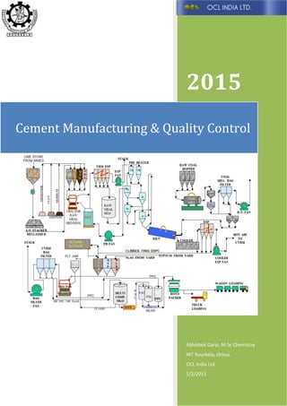
  • 28. Abhishek Garai (M.Sc Chemistry) NIT Rourkela, Orissa Page 27 Morrum Sandstone Clay Hopper for proper Raw mix Design Grinding Raw Meal Raw Meal Silo Vertical Roller mill for Grinding. Preheater Rotary Klin Clinker Production Process Co al Firi ADDITIVES (Gypsum, Slag, Fly Ash)
  • 29. Abhishek Garai (M.Sc Chemistry) NIT Rourkela, Orissa Page 28 The cement manufacture process from the mines to packing of cement can be divided into five steps:  Raw materials acquisition and handling.  Kiln feed preparation.  Clinker Production (Pyro-Processing).  Finished grinding.  Packing & Dispatch. Each of these steps are described briefly below.  Raw materials acquisition and handling: The initial production step in Portland cement manufacturing is raw materials acquisition. Calcium, the element of highest concentration in Portland cement, is obtained from a variety of calcareous raw materials, including limestone, chalk, marl, sea shells, aragonite, and an impure limestone known as "natural cement rock". Typically, these raw materials are obtained from open-face quarries, but underground mines or dredging operations are also used. Raw materials vary from facility to facility. Some quarries produce relatively pure limestone that requires the use of additional raw materials to provide the correct chemical blend in the raw mix. The raw materials are selected, crushed, and proportioned so that the resulting mixture has the desired the minimum percentage of chemical composition requirement of raw materials. Because a large fraction (approximately one third) of the mass of this primary material is lost as carbon dioxide (CO2) in the kiln, Portland cement plants are located close to a calcareous raw material source whenever possible. The raw materials limestone is then transported to the plant by Cross Country Belt Conveyer (CCBC) or by railway wagons.  Stacking and Reclaiming of Limestone: After crushing, the crushed limestone is piled longitudinally by an equipment called stacker / reclaimer. The stacker deposits limestone longitudinally in the form of a pile. The pile is normally 250 to 300 m long and 8-10 m high. The reclaimer cuts the pile vertically, simultaneously from top to bottom to ensure homogenization of limestone.
  • 30. Abhishek Garai (M.Sc Chemistry) NIT Rourkela, Orissa Page 29 The crushed limestone from pile is transported through belt conveyor to hopper. Similarly, other raw materials like clay, morrum, sand stone etc. are also transported by belt conveyor from storage yard to respective hoppers. All raw materials are proportioned in requisite quantity through weigh feeders.  Crushing Stacking and Reclaiming of Coal: The process of making cement clinker requires heat. Coal is used as the fuel for providing heat. Raw Coal received from collieries is stored in a coal yard. Raw Coal is dropped on a belt conveyer from a hopper and is taken to and crushed in a crusher. Crushed coal discharged from the Coal Crusher is stored in a longitudinal stockpile from where it is reclaimed by a reclaimer and taken to the coal mill hoppers for grinding of the coal. Stacker of Limestone Stacker of Coal Reclaimer of Lime Stone Reclaimer of Coal
  • 31. Abhishek Garai (M.Sc Chemistry) NIT Rourkela, Orissa Page 30  Kiln Feed preparation: The second step in Portland cement manufacture is preparing the raw mix, or kiln feed, for the pyroprocessing operation. Raw material preparation includes a variety of blending and sizing operations that are designed to provide a feed with appropriate chemical and physical properties. Based on Raw mix design and availability of additives and quality of limestone received, proportioning of raw materials is achieved through electronically controlled weigh feeders. Cement raw materials are received with an initial moisture content varying from 1 to more than 50 percent. If the facility uses dry process kilns, this moisture is usually reduced to less than 1 percent before or during grinding. Drying alone can be accomplished in impact dryers, drum dryers, paddle-equipped rapid dryers, air separators, or autogenous mills. However, drying can also be accomplished during grinding in ball-and-tube mills or roller mills. While thermal energy for drying can be supplied by exhaust gases from separate, direct-fired coal, oil, or gas burners, the most efficient and widely used source of heat for drying is the hot exit gases from the pyroprocessing system.  Raw Mix design:
  • 32. Abhishek Garai (M.Sc Chemistry) NIT Rourkela, Orissa Page 31 Limestone and other additives in desired proportions are fed to Vertical Roller Mill (VRM) by belt conveyer where they are ground to fine powder. A part of the hot exit gas (from the kiln) that has been sucked by the pH fan is sent to VRM through GAS CONDITIONING TOWER (GCT-to reduce temperature) to remove the moisture in the raw materials. The dust produced is carried by the hot gas and it is separated by Electro Static Precipitator (ESP) by charging the dust particles which then fall into hopper for recycling. The ‘Raw Meal’ produced after grinding by Vertical roller mill is air swept from inside from VRM and transported to specially designed ‘RAW MEAL SILO’ where blending is done by injecting compressed air for maintaining its homogeneous nature. VRM: Raw meal is ground in VRM to give a residue of +90µm 12-14%. VRM contains a horizontal circular table rotated by a motor and three conically tapered grinding roller. Material grinding process motor through reducer rotating drive disc, the material falls from the mill under the central entrance and exit, under the action of centrifugal force to the disc edge by the roller to move and the crushing, grinding out lap after the material was speed up the flow to and vertical mill with one of the separator, after the meal by the separator back to the mill, the re-grinding; powder while grinding out with air, dust collection equipment in the system to collect down, that is, products.
  • 33. Abhishek Garai (M.Sc Chemistry) NIT Rourkela, Orissa Page 32 Established through the mill in the pneumatic conveying of materials, a larger air flow rate, which can use waste heat of gas, at the same time dry grinding operations. ESP: An electrostatic precipitator (ESP) is a filtration device that removes fine particles, like dust and smoke, from a flowing gas using the force of an induced electrostatic charge minimally impeding the flow of gases through the unit.  Clinkerisation (Pyroprocessing): The heart of the Portland cement manufacturing process is the pyroprocessing system. This system transforms the raw mix into clinkers, which are grey, glass-hard, spherically shaped nodules that range from 0.32 to 5.1 centimetres (cm) (0.125 to 2.0 inches [in.]) in diameter. The pyroprocessing system of clinkerisation section consists of a rotary kiln with 5 stage preheater with in line precalciner. In the preheater the raw meal gets heated up with the use of kiln waste gases, and in the precalciner the raw meal is partially calcined to the extent of 85 to 95% by partly firing coal in the precalciner with the help of hot air recovered from clinker cooler. The partially calcined raw meal enters the rotary kiln. Coal, ground to desired fineness is fired into kiln from the discharge end. In these rotary kilns a tube with a diameter up to 25 feet is installed at a 3-4 degree angle that rotates 1-3 times per minute. The ground raw material, fed into the top of the kiln, moves down the tube counter current to the flow of gases and toward the flame-end of Preheater
  • 34. Abhishek Garai (M.Sc Chemistry) NIT Rourkela, Orissa Page 33 the rotary kiln, where the raw meal is dried, calcined, and enters into the sintering zone. In the sintering (or clinkering) zone, the combustion gas reaches a temperature of 3300-3600 °F. While many different fuels can be used in the kiln, coal has been the primary fuel although now a days Pet Coke (Bi-Product of petroleum industry) are also used. The raw mix in the kiln melts first into liquid form and then transforms into nodules due to the effect of the rotation of the kiln. There are two zones inside the kiln, namely calcining zone and burning zone. The zone where raw mix enters into the kiln is called calcining zone. Where temperature would be 950- 1000 C. Burning zone starts after this zone where temperature would be 1350-1450 C. The chemical reactions and physical processes that constitute the transformation are quite complex, but they can be viewed conceptually as the following sequential events: 1. Evaporation of free water; 2. Evolution of combined water in the argillaceous components; 3. Calcination of the calcium carbonate (CaCO3) to calcium oxide (CaO); 4. Reaction of CaO with silica to form dicalcium silicate; 5. Reaction of CaO with the aluminium and iron-bearing constituents to form the liquid phase; 6. Formation of the clinker nodules; 7. Evaporation of volatile constituents (e. g., sodium, potassium, chlorides, and sulphates) 8. Reaction of excess CaO with dicalcium silicate to form tricalcium silicate. After the formation of clinker cooling is necessary for quality maintenance. The temperature of the clinker is brought to 80-90 oC from 1350-1450 oC by Clinker Cooler. Fast cooling is very essential to get good Rotary Kiln
  • 35. Abhishek Garai (M.Sc Chemistry) NIT Rourkela, Orissa Page 34 quality clinker. If cooling is not quick, the compound stability in clinker will be adversely affected resulting in lower strength of cement after grinding. The hot gas produced in the clinker cooler is used in kiln, VRM and pyro cyclone. The cooled clinker produced are transported to Clinker storage Silo by Deep Drawn Pan Conveyer (DDPC). Clinker
  • 36. Abhishek Garai (M.Sc Chemistry) NIT Rourkela, Orissa Page 35
  • 37. Abhishek Garai (M.Sc Chemistry) NIT Rourkela, Orissa Page 36  Finish Grinding: The final step in cement manufacturing involves a sequence of blending and grinding operations that transforms clinker to finished cement. To produce powdered cement clinker is ground to the consistency of face powder. The clinker from silos are fed into grinding ball mill or vertical roller mill along with requisite amount of gypsum and other additives like Fly ash , Slag etc depending on the requirement of proper strength, setting time.  Packing & Dispatch: The Cement produced after grinding are stored in silos from where it is extracted to automatic rotopackers with electronically controlled weight capacity. When the cement packing bag is of 50 kg it will automatically stop pouring into that bag after the bag will be automatically sealed and transported to bag cement storage. After that cement is being loaded in the wagons and racks through automatic loaders and finally dispatch in rail and road. VRM Automatic Rotopackers
  • 38. Abhishek Garai (M.Sc Chemistry) NIT Rourkela, Orissa Page 37 The quality of cement in India is maintained according to “Bureau of Indian Standards” specifications. The quality is assured by the analysis of raw materials, clinker, and cement in regular basis according to BIS procedure. Apart from that the processing parameter in Kiln, silo, VRM are also maintained by CCR. ASSURENCE PROCEDURE: Objective: a) Ensuring the quality of the incoming, intermediate, semi-finished and final product. b) Ensuring conformity with the laid down norms by BIS (Bureau of Indian Standards.)  QUALITY CONTROL OF INCOMING MATERIALS. LIMESTONE: Limestone is the predominant raw materials in cement manufacturing its quality ultimately characterises the quality of clinker and cement. Time to time limestone samples are tested at laboratory to evaluate the deposit of quarry by computer aided Deposit Evaluation by M/S Holtech Consultancy. Day to day drill dust samples analysis are done at laboratory and the results are communicated to quarry enabling them to make the pre blend for dispatching the uniform quality of lime stone. As peer pre blended, limestone are crushed and loaded in the hopper and finally it is transported to the plant by Cross Country Belt Conveyer sometimes by Narrow Gauge Train lines. The material is stacked horizontally trough stacker to form a cheveron type of stockpile up to a quantity of 1500 MT. During stacking the quality is monitored and the samples are being collected from the belt in hourly basis through a continuous auto sampling
  • 39. Abhishek Garai (M.Sc Chemistry) NIT Rourkela, Orissa Page 38 system and analysed through X-Ray analyser. The test results are fed to the quarry on hourly basis to take the necessary correction before the next dispatch to meet the prefixed norms for every 5000 MT stock. The cumulative chemical composition of the limestone stockpile is estimated based on the hourly test results and use to prepare the raw mix design. QUALITY CONTROL OF OTHER ADDITIVES: Clay, Fly ash, Cinder, Morrum are the additives are generally used in the raw meal although some other additives are also can be used. Received raw materials are tested to check its conformity w.r.t the predefined norms. The test data are used for preparing the raw mix design. Coal is used mainly as a fuel although Pet coke are also used now a days. Received Coal and pet Coke are tested to check its conformity w.r.t to the predefined norms. Blast furnace granulated slag, fly Ash, and gypsum are used in the cement grinding stage. The received materials are tested to check its conformity w.r.t to predefined norms laid down by BIS.  QUALITY CONTROL OF RAWMEAL. Raw Meal: Limestone stockpile is being reclaimed vertically trough a reclaimer to get a uniform quality of limestone all along. The limestone is intimately mixed with known quality of argillaceous materials in a definite proportion through weigh feeders as determined by the QCX blend expert system based on the quality targets of the raw meal determined through raw mix design. This mixed materials is ground in a vertical roller mill. The mill output materials is stored inside the specified silos. During grinding process samples are being collected on hourly basis through a continuous auto sampling system and being tested through X-Ray fluorescence spectrometer. The results are in turn fed to QCX blend expert system to change the proportion of raw materials to meet the target values.
  • 40. Abhishek Garai (M.Sc Chemistry) NIT Rourkela, Orissa Page 39 QUALITY CONTROL OF INTERMEDIATE MATERIALS. Clinker: The raw meal from the silo is fed to the kiln through two string five stages preheater with inline calciner and sintered at a temp of 1400 degree centigrade for complete clinker formation. The clinker is then passed through a grade cooler and stored in the Clinker Gantry. The fuel used in the pyro system is coal pulverised through a ball mill and the samples is being taken to check and maintain the ash content to meet the target value. Hourly clinker sample is collected from DDPC and is being tested by X-Ray Fluorescence spectrometer and X-ray Diffractometer for their complete elemental composition and phase evaluation. This definitely helps for controlling and monitoring the clinker quality as per the target designed value on hourly basis and for taking any effective action in the raw meal if required. QUALITY CONTROL OF FINAL PRODUCT. Cement Grinding: Known quality of Clinker, Gypsum, Slag, Fly Ash are fed into respective hoppers of the grinding mills from which required proportion of these materials are fed to the mills through weigh feeders as per the requirement of manufacturing different quality of cement. Mills out samples are collected through continuous auto sampling system a tested for complete quality evaluation and taking necessary corrective actions. Cement Packing: Finally the cement is packed through automatic rotopackers. During packing samples are being collected through autosamplers on hourly basis to assure the quality of cement supplied to the customers. Ensuring Conformity with the laid down norms by BIS To ensure the compliance of statutory requirements of BIS following activities are performed-
  • 41. Abhishek Garai (M.Sc Chemistry) NIT Rourkela, Orissa Page 40  All IS specifications required for carrying out the quality control functions are identified and kept in a separate file at an identified location.  Incase of any amendment or change in version of IS specification the old one is replaced and new version is incorporated in the file.  The test records related to the quality input and output of the products required to provide evidence of conformity to the IS requirements are maintained and duly signed by the respective authorised person.  Sectional Incharge is authorized to ensure compliance of statutory requirements of BIS.  Action is initiated for timely renewal of the product licenses. The following analysis are done in prescribed time intervals for assuring the quality -
  • 42. Abhishek Garai (M.Sc Chemistry) NIT Rourkela, Orissa Page 41 Total 3 type of tests are done in cement industry namely 1. Chemical Analysis. 2. Physical Analysis. 3. Fuel Analysis.  Chemical Analysis (Various Technique used for analysis and their principle of operation): Chemical analysis is required in cement manufacture for evaluating the quality of raw materials, raw meal & finish grinding product and for effecting quality control. Chemical composition is determined by two methods-  Instrumental Techniques.  Laboratory tests.  Instrumental Techniques. Now the chemical composition and other properties of cement, clinker, raw materials can be is easily determined by using instrument like - 1. X-ray Fluorescence Spectrometer. 2. X-Ray Diffraction. 3. Microscope. 4. Flame Photometer. Let us discuss about those instruments and their principle of operation. Principle: Samples for X-ray fluorescence are prepared by grinding the samples with cellouse power and then pressed under the pressure of 20 ton for 10-15 seconds and make sample pellet. The samples are excited by an X-ray radiation produced in X
  • 43. Abhishek Garai (M.Sc Chemistry) NIT Rourkela, Orissa Page 42 ray tube operated in a potential between 10-100 kv. When materials are exposed to short wavelength X-rays or to gamma rays, ionization of their component atoms may take place. Ionization consists of the ejection of one or more electrons from the atom, and may occur if the atom is exposed to radiation with an energy greater than its ionization potential. X-rays and gamma rays can be energetic enough to expel tightly held electrons from the inner orbitals of the atom. The removal of an electron in this way makes the electronic structure of the atom unstable, and electrons in higher orbitals fall into the lower orbital to fill the hole left behind. In falling, energy is released in the form of a photon, the energy of which is equal to the energy difference of the two orbitals involved. Thus, the material emits radiation, which has energy characteristic of the atoms present. The term fluorescence is applied to phenomena in which the absorption of radiation of a specific energy results in the re-emission of radiation of a different energy (generally lower). The intensity of these characteristic radiation is measured with a suitable x ray spectrometer and it is compared with standard samples. Calibration: In preparing an analytical program to measure unknown concentration trough XRF it is necessary to make a series of standard samples with known concentrations for all the elements to be measured .These samples are called calibration samples. Calibration samples are grouped by matrices. The name of the matrices represents the link with a
  • 44. Abhishek Garai (M.Sc Chemistry) NIT Rourkela, Orissa Page 43 calibration is a process to relate measured element intensities of concentration. Procedure:  For a particular analytical program minimum 6 samples of the same matrix and different range of element are to be selected and analysed trough conventional method of chemical analysis.  The samples are to be pelletized as per WI No CFQA0308.  Intensity is measured for the programmed element.  These intensity are stored in computer under selected analytical program.  Element wise chemical analysis data (concentration) of different samples are also stored for that particular analytical program.  The computer plots calibration curve for each of the element for the particular analytical program.  When an unknown samples is excited with X ray radiation it emits the fluorescence radiations with characteristic wavelength of each elements. The intensity of those fluorescence radiation of each element are measured and compared with that of the standard samples from the calibration curve to calculate the corresponding concentration. Calibration Curve
  • 45. Abhishek Garai (M.Sc Chemistry) NIT Rourkela, Orissa Page 44 X-ray powder diffraction (XRD) is a rapid analytical technique primarily used for phase identification of a crystalline material and can provide information on unit cell dimensions. The analysed material is finely ground, homogenized, and average bulk composition is determined. Principle: Max von Laue, in 1912, discovered that crystalline substances act as three-dimensional diffraction gratings for X-ray wavelengths similar to the spacing of planes in a crystal lattice. X-ray diffraction is now a common technique for the study of crystal structures and atomic spacing. X-ray diffraction is based on constructive interference of monochromatic X-rays and a crystalline sample. These X-rays are generated by a cathode ray tube, filtered to produce monochromatic radiation, collimated to concentrate, and directed toward the sample. The interaction of the incident rays with the sample produces constructive interference (and a diffracted ray) when conditions satisfy Bragg's Law (nλ=2d sin θ). This law relates the wavelength of electromagnetic radiation to the diffraction angle and the lattice spacing in a crystalline sample. These diffracted X-rays are then detected, processed and counted. By scanning the sample through a range of 2θ angles, all possible diffraction directions of the lattice should be attained due to the random orientation of the powdered material. Conversion of the diffraction peaks to d-spacings allows identification of the mineral because each mineral has a set of unique d-spacings. Typically, this is achieved by comparison of d-spacings with standard reference patterns. All diffraction methods are based on generation of X-rays in an X-ray tube. These X-rays are directed at the sample, and the diffracted rays are collected. A key component of all diffraction is the angle between the incident and diffracted rays. Powder and single crystal diffraction vary in instrumentation beyond this.
  • 46. Abhishek Garai (M.Sc Chemistry) NIT Rourkela, Orissa Page 45 Applications: XRD is used for phase identification of cement clinker. Difficulty in cement identification results in large peak overlap but also in large polymorphs coexistence. Indeed, C3S exists in 3 different forms: Monoclinic, Triclinic and Rhomboedric. C2S can also exist in 3 different polymorphs: α, β and γ. However, C2S beta is the most used and expected due to its reactivity; it is the most common in cement. α shows a slower reactivity and γ does not react. C3A is also well known to have two possible polymorphs in cement like cubic or orthorhombic phases. Moreover, more to the polymorph coexistence, some trace phases are present (lime, portlandite, periclase…) and some additives are added in cement to improve final properties. Gypsum is one of them and will control the milling dehydration process; this phase is often accompanied with bassanite, anhydrite and hemi hydrate phases. Phase identification takes place in three steps: background subtraction is the first one and it is always required in this kind of material, then a peak finder procedure has to be performed and finally a search/match can be processed quickly. For a more efficient search/match, a cement database can be created with the software. Scan of calcium aluminate cement during hydration process Peak intensity variation during hydration
  • 47. Abhishek Garai (M.Sc Chemistry) NIT Rourkela, Orissa Page 46 A valuable, simple, very handy, inexpensive, low maintenance cost quality control tool for quality evaluation of clinker, limestone, kiln feed, aggregates and slag. Common Morphological features of clinker phases.
  • 48. Abhishek Garai (M.Sc Chemistry) NIT Rourkela, Orissa Page 47 Optical Properties of Clinker Phases. Sl.no Clinker Phase Colour Shape Microstructure 1. ALITE-C3S (3CaO,SiO2) STRAW YELLOW, BROWN, YELLOWISH BROWN, BROWNISH YELLOW HEXAGONAL, PSEUDO- HEXAGONAL, LATH, SUBHEDRAL, ANHEDRAL ETC. FUSED GRAINS, STRETCHED, TWINNED, GRANULATED, BROKEN OUT LINE GRAIN 2. BELITE-C2S (2CaO,SiO2) BLUE, BLUISH YELLOW YELLOWISH BLUE,GREENISH YELLOW, YELLOWISH GREEN ROUNDED SUB ROUNDED ELLIPTICAL, SUBHEDRAL, ANHEDRAL ETC. CLUSTERS OF VARIOUS SIZE, FUSED GRAINS, TWINNED GRAINS, CORRODED GRAIN MARGINS, STRIATIONS ON BELITE GRIN SURFACES, AS INCLUSION. 3. FREE LIME - CaO MULITPLE HIGH ORDER INTERFERENCE COLOURS OF PINK, GREEN, YELLOW, BLUE ETC. ROUNDED, SUB- ROUNDED, SUBHEDRAL, ANHEDRTAL ETC. CLUSTERS, STRIATIONS ON THE GRAIN SURFACES, AS INCLUSIONS
  • 49. Abhishek Garai (M.Sc Chemistry) NIT Rourkela, Orissa Page 48 Pictures of different forms: By using this microscopic technique both qualitatively and quantitatively we can measure the phases and composition in clinker and cement in different forms. A photoelectric flame photometer is a device used in inorganic chemical analysis to determine the concentration of certain metal ions, among them sodium, potassium, lithium, and calcium. Group 1 and Group 2 metals are quite sensitive to Flame Photometry due to their low excitation energies. Alite Balite Free Lime
  • 50. Abhishek Garai (M.Sc Chemistry) NIT Rourkela, Orissa Page 49 In principle, it is a controlled flame test with the intensity of the flame colour quantified by photoelectric circuitry. Flame photometry is concerned with the emission of characteristic radiation in flame and correlation of emission intensity with the concentration of the solution. When a liquid sample containing a metallic salt solution is introduced in the flame, the solvent get vaporized leaving particles of the solid salt. The atoms are ionised and get thermally excited and go to the higher energy state, when they come into lower energy state these atom release same amount of energy. If E1 and E2 represent the higher and lower energy state respectively then the radiation emitted during the transition may be defined as the following equation E1-E2=hγ. So the intensity of the colour will depend on the energy that had been absorbed by the atoms that was sufficient to vaporise them. The sample is introduced to the flame at a constant rate. Filters select which colours the photometer detects and exclude the influence of other ions. Before use, the device requires calibration with a series of standard solutions of the ion to be tested. From this flame photometry chemical composition in of unknown cement sample, raw materials can be determined through calibration plot with respect to the intensity of standard solution. Instrumentation:- Generally the flame photometer has six parts i. Pressure Regulator ii. Atomizers iii. Burner iv. Optical System v. Photosensitive Detector vi. Instrument for recording the output of the detector.
  • 51. Abhishek Garai (M.Sc Chemistry) NIT Rourkela, Orissa Page 50 Procedure:- 1. Turn on the flame photometer and adjust the air pressure to 0.5 Kg/cm2.Adjust the fuel and light of the burner to get a clear conical flame. 2. Rinse the atomiser with distilled water for half an hour. 3. Select the filter what you want to determine like Na2O, K2O etc. 4. Aspirate the reagent blank solution and set the digital reading at 0. 5. Aspirate the 10 ppm solution and adjust the digital reading at 100. 6. Readjust the zero with blank. 7. Aspirate the 1,2,4,6,8,10 ppm solution and note the reading. 8. Draw the calibration curve of ppm vs digital reading. 9. Now the ppm of the unknown samples are estimated by using the following formula. PPM= Concentration in ppm * Volume in ml *Dilution Factor *100 Weight of the samples * 106  Laboratory Tests. Although various methods are available for the quantitative estimation of the different composition in cement, clinker, raw materials. But in India the estimation is done by following “IS-4032- 1985” procedure of Bureau of Indian Standards. Conventional chemical analysis is done mainly on two methods – 1. Gravimetric Method. 2. Volumetric and Complexmetric Method. 1. Gravimetric Method. It is the process of sequential & weighting an element or definite compound of the element in as pure form as possible. The compound is precipitated filtered and then ignited t give the most suitable form of the element for weighting. 2. Volumetric and Complexmetric Method: It is quantitative chemical quantitative chemical analysis by measure consists essentially in determining the volume of the solution of accurately known concentration which required to react quantitatively with the substrate being determined. In Complexmetric method the metals react with the indicator and gives a colour at a controlled pH. The volume of the
  • 52. Abhishek Garai (M.Sc Chemistry) NIT Rourkela, Orissa Page 51 polydentate ligand complexes with the metal cation realising the indicator. Which gives a different colour. Chemical analysis is done mainly to determine the following things.  % of LOI (Loss on Ignition).  % of Fe2O3.  % of CaO.  % of SiO2.  % of MgO.  % of SO3.  % of Na2O  % of K2O. % of LOI (Loss on Ignition): Loss on ignition is determined by taking a known weight of sample approx. 1.0 gm accurately weighted in a platinum crucible and heated in a Muffle Furnace for 15-20 min in a temperature range of 1000-1200 o C. Then the sample is cooled in desiccator and the weight of the sample taken. Repeat the procedure till the constant weight observed. Loss on ignition = (W1-W2)*100 W W1= Weight of the sample + Weight of the crucible. W2= Weight of the empty crucible. W = Weight of the sample taken.  % of Fe2O3 Procedure for determination of Fe2O3 by K2Cr2O7 in Clinker, Cement and Gypsum:
  • 53. Abhishek Garai (M.Sc Chemistry) NIT Rourkela, Orissa Page 52 1. 1 gm of sample is weighted accurately and taken in 400 ml Beaker and dissolved in concentrated HCl and around 100 ml of distilled water and transfer in 500 ml conical flask. 2. The solution is boiled with some porcelain chips. 3. Fe 3+ is reduced to Fe 2+ by adding SnCl2 drop wise till the solution become colourless. Rxn: Sn2+ - 2e Sn4+ 2Fe3++2e 2 Fe2+ 4. The flask is cooled rapidly to room temperature and 20-25 ml Mercuric Chloride is added followed by sulphuric Orthophosphoric acid into the solution. 5. 3-4 drops of Barium Di-phenyl amino sulphonate indicator is added and titrate against (N/16) K2Cr2O7 solution till a stable violet –blue end point appears. 6. % of Fe2O3 = ( Consumption of K2Cr2O7)/2 Procedure for determination of Fe2O3 by K2Cr2O7 in LIMESTONE, Additives and other than MORRUM and Raw Meal. 1. Weight accurately 1 gm of sample in a platinum crucible 2. Add around 8-10 gm of fusion mixture in it and fuse it in a muffle furnace at 950 C for 15-20 min. 3. Extract the sample with 1 N of 100 ml of 1:1 HCl. 4. Add 5-6 of Bromine water to the solution and keep it on heater till complete evaporation of the Bromine Water. 5. Remove the solution from the heater and around 10 gm of solid Ammonium chloride and dissolve it by stirring with a glass rod. 6. Add ammonium hydroxide drop wise to the solution till complete precipitation. 7. Warm the solution on the heater and filter through 541 whatmann filter paper. 8. Wash the residue with hot distilled water. 9. Transfer the residue in a 500 ml conical flask and dissolve in concentrated HCl. 7. The solution is boiled with some porcelain chips.
  • 54. Abhishek Garai (M.Sc Chemistry) NIT Rourkela, Orissa Page 53 8. Fe 3+ is reduced to Fe 2+ by adding SnCl2 drop wise till the solution become colourless. Rxn: Sn2+ - 2e Sn4+ 2Fe3+ + 2e 2 Fe2+ 10. The flask is cooled rapidly to room temperature and 20-25 ml Mercuric Chloride is added followed by sulphuric Orthophosphoric acid into the solution 11. 3-4 drops of Barium Di-phenyl amino sulphonate indicator is added and titrate against (N/16) K2Cr2O7 solution till a stable violet –blue end point appears. 12. % of Fe2O3 = ( Consumption of K2Cr2O7)/2 13. % of Fe2O3 = ( Consumption of K2Cr2O7)*2.5 (for Morrum) Calculation: Molar Weight of Fe2O3 = (55.847*2) +48 = 159.694 Molar weight of K2Cr2O7 = (39.0983*2) + (51.996*2)+16*7=294.1886 1 N K2Cr2O7 = (294.1886/6)=49.03 gm 1 N K2Cr2O7 = 159.694/2=79.847 gm Fe2O3 1 ml of 1 N K2Cr2O7 =0.07985 gm of Fe2O3 For 0.5 gm sample if we want to recg. a factor of 1 the normality of the K2Cr2O7 solution will be – F= Normality of K2Cr2O7 *0.07985*100/0.5 Normality = (1*0.5)/(0.07985*100)=0.62617N=(N/16)  % of CaO: Procedure for determination of CaO by KMnO4 for GYPSUM, CLINKER, and CEMENT: 1. 0.5 gm of sample is weight and take in 500 ml beaker. 2. Dissolve it with concentrated HCl and some distilled water is added to make the solution. 3. One two drop of methyl orange is add and heat. 4. Reduce the colour of the solution by drop wise addition of ammonium hydroxide of yellow colour.
  • 55. Abhishek Garai (M.Sc Chemistry) NIT Rourkela, Orissa Page 54 5. Again add oxalic acid and bring the colour to red. 6. Add 50 ml of ammonium oxalate to the boiled solution. 7. Cool down to 50-60 C then filter with whatmann 41 and wash the residue with distilled water. 8. Titrate against 0.18 N KMnO4 solution. 9. % of CaO= Consumption of KMnO4*factor. Preparation and standardisation of KMnO4 Solution and determination of Factor. 1. Dissolve 5.6 gm of KMnO4 per litre distilled water and mix it properly. 2. Standardise the solution by taking 0.67 gm of sodium oxalate and dissolving it 10 ml 1:1 H2SO4 mixed with 10 ml of hot distilled water. Then titrate against the prepared KMnO4 soln. Let’s the consumption be X ml Factor = (Consumption of KMnO4 soln)/56. Procedure for determination of CaO by KMnO4 for LIMESTONE, CLAY, SHALE, MORRUM, RAW MEAL AND COAL ASH: 1. Weight accurately 1 gm of sample in a platinum crucible. 2. Add around 10-15gm of fusion mixture and heated in a muffle furnace at 900 C for 15 minutes. 3. Extract the sample with 1 N of 100 ml of 1:1 HCl. 4. Add 5-6 of Bromine water to the solution and keep it on heater till complete evaporation of the Bromine Water. 5. Remove the solution from heater and add 10 gm of Ammonium chloride added and dissolve it by stirring it by glass rod. 6. Add Ammonium hydroxide drop wise until precipitation. 7. Warm the solution on heater and filter it through whatmann 541 filter paper. 8. Collect the filtrate in 600 ml beaker and wash the residue by hot distilled water for two three times. 9. Boil the filtrate and add boil Ammonium Oxalate about 80 ml and further boil it. 10. Cool the solution and allow the precipitate to settle down. 11. Filter the solution through double 41 filter paper and wash the precipitate by distilled water.
  • 56. Abhishek Garai (M.Sc Chemistry) NIT Rourkela, Orissa Page 55 12. Take out the precipitate along with the filter paper and dissolve it by 15 ml 1:1 H2SO4 along with 15 ml of distilled water. 13. Titrate against 0.18 N of KMnO4 14. % of CaO = (Consumption of KMMnO4 solution/2)* Factor. 15. The factor is determined as per the method described earlier.  % of SiO2 1. SiO2(Silicon dioxide) Silica is one of the major constituents of the raw materials required for cement. It is usually analysed by volumetric method. The soluble silicates e.g. Clinker and cement are decomposed by HCl, The insoluble silicates like clay and pozzolanic materials, raw mix are made soluble by treating with fusion mixture. This is followed by double evaporation to convert silicon dioxide to insoluble form. The solution is filtered and the insoluble silica in residue is ignited and weighted. Silicon dioxide is volatilized in the form of silicon tetra fluoride by hydrofluoric acid in presence of sulphuric acid. The loss of weight is reported as pure SiO2. The reaction involved are following- MSiO3+2HCl=MCl2+H2SiO3 m= Silicic Acid 2MSiO3 + Na2O3+K2CO3 = 2MCO3 + Na2SiO3 + K2SiO3 Insoluble silicate Fusion Mixture MCO3+ Na2SiO3+K2SiO3+6HCl = MCl2+2NaCl+2KCl+CO2 +2H2SiO3+H2O H2SiO3+H2O=H2SiO4 H2SiO4 +nH2O= H2SiO4, nH2O SiO2 + Impurities +4HF=SiF4 + 2H2O 3 SiF4+ 3H2O= H2SiO3 + 2 H2SiF6 Silicic Acid Hydrofluoro Silicic Acid 1.1 Transfer 0.5 g of the sample to an evaporating dish, moisten with 10 ml of distilled water at room temperature to prevent lumping, add 5 to 10 ml of hydrochloric acid, and digest with the aid of gentle heat and agitation until the sample is completely dissolved. Dissolution may be aided by light pressure with the flattened end of a glass rod. Evaporate the solution to
  • 57. Abhishek Garai (M.Sc Chemistry) NIT Rourkela, Orissa Page 56 dryness on a steam-bath. Without heating the residue any further treat it with 5 to 10 ml of hydrochloric acid and then with an equal amount of water, or pour at once upon the residue 10 to 20 ml of hydrochloric acid (1 : 1). Then cover the dish and digest for 10 minutes on the water- bath or hot-plate. Dilute the solution with an equal volume of hot water, immediately filter through an ash less filter paper (Whatman No. 40 or its equivalent), and wash the separated silica (SiO2) thoroughly with hot water and reserve the residue. 1.2 Again evaporate the filtrate to dryness, baking the residue in an oven for one hour at 105 to 110°C. Then treat the residue with 10 to 15 ml of hydrochloric acid (1:1) and heat the solution on water-bath or hot-plate. Dilute the solution with an equal volume of hot water catch and wash the small amount of silica it contains on another filter paper. Reserve the filtrate and washings for the determination of combined alumina and ferric oxide. 1.3 Transfer the papers containing the residues to a weighed platinum crucible. Dry and ignite the papers, first at a low heat until the carbon of the filter paper is completely consumed without inflaming, and finally at 1 100 to 1 200°C until the weight remains constant. 1.4 Treat the ignited residue thus obtained, which will contain small amounts of impurities, with 1 to 2 ml of distilled water, about 10 ml of hydrofluoric acid and 2 drops of sulphuric acid and evaporate cautiously to dryness. Finally heat the small residue at 1050 to 1100°C for a minute or two; cool and weigh. The difference between this weight and the weight of ignited sample represents the amounts of silica: Silica percent = 200 (W1 - W2) Where W1 = weight of silica + (insoluble impurities - residue), and W2 = weight of impurities. 1.4.1 To this amount of silica, add the amount of silica recovered from the residue derived from the combined precipitates of alumina and ferric oxide as indicated under 1.5
  • 58. Abhishek Garai (M.Sc Chemistry) NIT Rourkela, Orissa Page 57 So the total percentage of silica will be = (W1-W2) +W3 ×100 W4 Where W1= Weight of the silica and insoluble impurities W2= Weight of the crucible after hydrofluorization W3=Weight of the silica recovered from iron and aluminium oxide W4=Weight of the sample taken. 1.5 Add 0.5 g of sodium or potassium persulphate to the crucible and heat below red heat until the small residue of impurities is dissolved in the melt. Cool, dissolve the fused mass in water, and add it to the filtrate and washings reserved for the determination of the combined alumina and ferric oxide.  % of Fe2O3, Al2O3, CaO and MgO(Gravimetric & EDTA) 2. Fe2O3 (Iron Oxide) 2.1 Method 1 (Potassium Permanganate Method) — To one gram of the sample, add 40 ml of cold water and, while the mixture is being stirred vigorously, add 15 ml of hydrochloric acid. If necessary, heat the solution and grind the cement with the flattened end of a glass rod until it is evident that the cement is digested fully. Heat the solution to boiling and treat it with stannous chloride solution added drop by drop while stirring, until the solution is decolourized. Add a few drops of stannous chloride solution in excess and cool the solution to room temperature. Rinse the inside of the vessel with water, and add 15 ml of a saturated solution of mercuric chloride in one lot. Stir, add 25 ml of manganese sulphate solution and titrate with standard solution of potassium permanganate until the permanent pink colour is obtained. Calculate iron as ferric oxide. 2.2 Method 2 (EDTA Method) Prepare filtrate as given in 1.2 and 1.5. Mix the filtrates and make up the volume in a 250-ml volumetric flask. 2.2.1 Take 25 ml of solution reserved in 2.2 and add dilute ammonium hydroxide (1 : 6) till turbidity appears. Clear the turbidity with a minimum amount of dilute hydrochloric acid (1:10) and add a few drops in excess to adjust the pH to approximately 1 to 1.5. Shake well. Then add 100 mg of
  • 59. Abhishek Garai (M.Sc Chemistry) NIT Rourkela, Orissa Page 58 sulphosalicylic acid and titrate with 0.01 M EDTA solution carefully to a colourless or pale yellow solution. 2.2.2 Calculation — Calculate the percentage of Fe2O3 as below: 1 ml of 0.01 M EDTA ≡ 0.7985 mg of Fe2O3 Iron oxide (Fe2O3) percent = (.7985*V)/W Where V = Volume of EDTA used in ml, and W = Weight of the sample in g. 3. Alumina (Al2O3) 3.1 Method 1 (Gravimetric Method) — Subtract the calculated weight of ferric oxide and small amount of silica from the total weight of oxides found under 4.4.3. The remainder is the weight of alumina and small amounts of other oxides which are to be reported as alumina. 3.2 Method 2 (EDTA Method) — Take 25 ml of solution reserved under 2.2 and titrate iron at pH approximately 1 to 1.5 with EDTA using sulphosalicylic acid as indicator. Add 15 ml standard EDTA solution. Add 1 ml of phosphoric acid (1 : 3), 5 ml of sulphuric acid (1 : 3) and one drop of thymol blue into the titration flask. Add ammonium acetate solution by stirring until the colour changes from red to yellow. Add 25 ml of ammonium acetate in excess to obtain pH approximately 6. Heat the solution to boiling for one minute and then cool. Add 50 mg of solid xylenol orange indicator and bismuth nitrate solution slowly with stirring until the colour of the solution changes from yellow to red. Add 2 to 3 ml of bismuth nitrate solution in excess. Titrate with 0.01 M EDTA solution to a sharp yellow end point red colour. 4.6.2.1 Calculation — Calculate the percentage of Al2O3 as below: V = V1 - V2 - (V3 × E) Where V= Volume of EDTA for alumina in ml, V1=Total volume of EDTA used in the titration in ml, V2 = Volume of EDTA used for iron in ml, V3= Total volume of bismuth nitrate solution used in the titration in ml, and E= Equivalence of 1 ml of bismuth nitrate solution. 1 ml of 0.01 M EDTA≡0.5098 mg of Al2O3
  • 60. Abhishek Garai (M.Sc Chemistry) NIT Rourkela, Orissa Page 59 Aluminium oxide (Al2O3) percent = (0.5098*V)/W Where W = Weight of the sample in g. NOTE — Equivalence of bismuth nitrate solution is obtained as follows: Transfer 100 ml of bismuth nitrate solution to a 500-ml flask and dilute with about 100 ml distilled water. Add a few drops of thymol blue solution and ammonium acetate solution until the colour changes from red to yellow. Add 50 mg of xylenol orange indicator and titrate with 0.01 M EDTA solution until the colour changes from red to yellow. The equivalence (ml of EDTA) of 1 ml of bismuth nitrate solution is calculated as follows: E = ----- 100 Where V4 = Volume of EDTA solution in ml. 4. CaO (Calcium Oxide): Method 1 (Gravimetric Method) — Acidify the combined filtrates set aside under 2.2 with hydrochloric acid and evaporate them to a volume of about 100 ml. Add 40 ml of saturated bromine water to the hot solution and immediately add ammonium hydroxide until the solution is distinctly alkaline. Boil the solution for 5 minutes or more, making certain that the solution is at all times distinctly alkaline. Allow the precipitate to settle; filter and wash with hot water. Wash the beaker and filter once with nitric acid (1.33) that has been previously boiled to expel nitrous acid, and finally with hot water. Discard any precipitate (of manganese dioxide) that may be left on the funnel. Acidify the filtrate with hydrochloric acid and boil until all the bromine is expelled. Add 5 ml of hydrochloric acid, dilute to 200 ml, add a few drops of methyl red indicator and 30 ml of warm ammonium oxalate solution. Heat the solution to 70 to 80°C and add the ammonium hydroxide (1 : 1) dropwise, while stirring, until the colour changes from red to yellow. Allow the calcium oxalate precipitate to stand without further heating for one hour, with occasional stirring during the first 30 minutes; filter through Whatmann filter paper No. 42 or equivalent, and wash moderately with cold 0.1 percent ammonium oxalate solution. Set aside the filtrate and washings for estimating magnesia.
  • 61. Abhishek Garai (M.Sc Chemistry) NIT Rourkela, Orissa Page 60 4.1 Dry the precipitate in a weighed, covered platinum crucible, char the paper without inflaming, burn the carbon at as low temperature as possible, and finally heat with the crucible tightly covered in an electric furnace or over a blast lamp at a temperature of 1100 to 1 200°C. Cool in a desiccator (to guard against absorption of moisture by ignited calcium oxide) and weigh as calcium oxide. Repeat the ignition to a constant weight. 4.2 Calculation — Calculate the percentage of CaO by multiplying the weight in grams of 200 residue (CaO) by 200 [100 divided by the weight of sample used (0.5 g)] CaO percent = weight of residue × 200 4.3 Method 2 (EDTA Method) — Take 10 ml of solution reserved under 2.2 in a 250-ml concial flask. Add 5 ml of 1:1 glycerol with constant stirring and 5 ml of diethylamine. To this add 10 ml of 4N sodium hydroxide solution and shake well to adjust pH to highly alkaline range of 12 or slightly more. Add approximately 50 ml of distilled water and 50 mg of solid Patton-Reeder’s indicator. Titrate against 0.01 M EDTA solution to a sharp change in colour from wine red to clear blue. 4.4 Calculations — calculate the percentage of CaO as below: 1 ml of 0.01 M EDTA≡ 0.5608 mg of CaO Calcium Oxide (CaO) percent = (.05608×25×V)/W Where V = Volume of EDTA used in ml, and W = Weight of the sample in g. 5. Magnesia (MgO) 5.1 Method 1 (Gravimetric Method) — Acidify the filtrate set aside under 4.1 with hydrochloric acid and concentrate to about 150 ml. Add to this solution about 10 ml of ammonium hydrogen phosphate (250 g/l) and cool the solution by placing in a beaker of ice water. After cooling, add ammonium hydroxide drop by drop, while stirring constantly, until the magnesium ammonium phosphate crystals begin to form, and then add the reagent in moderate excess (5 to 10 percent of the volume of the solution), the stirring being continued for several minutes. Set the solution aside for at least 16 hours in a cool atmosphere and then filter, using
  • 62. Abhishek Garai (M.Sc Chemistry) NIT Rourkela, Orissa Page 61 Whatmann No. 42 filter paper or its equivalent. Wash the precipitate with ammonium nitrate wash solution (100 g ammonium nitrate dissolved in water, 200 ml of ammonium hydroxide added and diluted to one litre). Place in a weighed platinum crucible, slowly char the paper and carefully burn off the resulting carbon. Ignite the precipitate at 1100 to 1200°C to constant weight taking care to avoid bringing the pyrophosphate to melting. The product of the weight of magnesia (MgO), pyrophosphate obtained and a factor, 0.3621, shall be the magnesium content of the material tested. 5.1.1 Calculation — Calculate the percentage of MgO as below: MgO percent = W × 72.4 5.2 Method 2 ( EDTA Method) — Take 10 ml of solution reserved under 2.2 Add 5 ml of 1:1 triethanolamine with constant shaking and 20 ml of buffer solution pH 10. Add 50 mg of the solid thymol phthalexone indicator followed by approximately 50 ml of distilled water. Titrate it against standard 0.01 M EDTA solution until the colour changes from blue to clear pink. This titration gives the sum of calcium and magnesium oxide present in the solution. Titre value of magnesium oxide is obtained by subtracting the titre value of calcium oxide from the total titre value. 5.2.1 Calculations — Calculate the percentage of MgO as given below: 1 ml of 0.01 M EDTA ≡ 0.4032 mg of MgO Magnesium oxide (MgO) percent =0.04032 × 25 × (V1-V2)/W Where V1= Volume of EDTA used in this titration in ml, V=Volume of EDTA used in CaO determination in ml, and W=Weight of the sample in g.  % of SO3 6. Sulphuric Anhydride — To one gram of the sample, add 25 ml of cold water, and while the mixture is stirred vigorously add 5 ml of hydrochloric acid. If necessary, heat the solution and grind the material with flattened end of a glass rod until it is evident that the decomposition of the cement is complete. Dilute the solution to 50 ml and digest for 15 minutes at a temperature just below boiling. Filter and wash the residue thoroughly
  • 63. Abhishek Garai (M.Sc Chemistry) NIT Rourkela, Orissa Page 62 with hot water. Set aside the filter paper with the residue. Dilute the filtrate to 250 ml and heat to boiling. Add slowly drop by drop, 10 ml of hot barium chloride (100 g/l) solution and continue the boiling until the precipitate is well formed. Digest the solution on a steam-bath for 4 hours or preferably overnight. Filter the precipitate through a Whatmann No. 42 filter paper or equivalent and wash the precipitate thoroughly. Place the filter paper and the contents in a weighed platinum or porcelain crucible and slowly incinerate the paper without inflaming. Then ignite at 800 to 900°C, cool in a desiccator and weigh the barium sulphate obtained, calculate the sulphuric anhydride content of the material taken for the test. 6.1 Calculation — Calculate the percentage of SO3 as follows: SO3 percent = W × 34.3 Where W= weight of residue (BaSO4) in g; and 34.3= molecular ratio of SO3 to BaSO4 (0.343), multiplied by 100. Chemistry Of EDTA titration: Ethylene Diamine tetra acetic acid (EDTA) disodium salt is a complexing agent, which form polydentate ligand with metal cations. In presence of metallo chrome indicator usually azodyes the metal forms metal indicator complex then reacts with EDTA and releases another colour. The change in colour should be sufficiently large to be observed by human eye, EDTA titration are pH sensitive. The reaction takes place for the titration is follows- NaOOC CH2 CH2 COONa N-CH2-CH2-N HOOC CH2 CH2 COOH M+In = Metal Indicator Complex MIn + Na2H2Y = MY-4 + 2 Na++ +2H++ + In EDTA Free Indicator
  • 64. Abhishek Garai (M.Sc Chemistry) NIT Rourkela, Orissa Page 63  % of Na2O & K2O Sodium and potassium oxide are determined by flame photometry using direct intensity principle. The Instrumentation and working principle of Flame Photometry is discussed in previous topic. Reagents and Materials: i. Aluminium Solution – Dissolve 10.85 g pure aluminium foil + 1 dop of mercury in 120 ml of concentrated nitric acid and 40 ml of 1:1 sulphuric acid, make up to 1 litre in a volumetric flask with distilled water. This aluminium sulphate solution contains 20000 ppm Al2O3. ii. Caesium Sulphate solution – Dissolve .41 g of caesium sulphate in distilled water and make upto 1 litre with distilled water. This solution contain 300 ppm (CS)2SO4. iii. Potassium Chloride (KCl) iv. Sodium Chloride (NaCl) v. Nitric Acid (Con.) Preparation of Solution: i. Sodium Potassium oxide stock solution: Analytical dry reagent grade of NaCl and KCl at 250 C, weight 0.1885 g of NaCl and 0.1583 g of KCl and dissolve in water and make up to 1 litre. This will correspond to 100 ppm of Na2O and K2O. ii. Reagent Blank Solution: Mix 2.5 ml nitric Acid, 2.5 ml of ammonium solution and 2.5 ml caesium sulphate solution make up to 250 ml of water. iii. Standard solution : Dispense 1,2,4,6,8 and 10 ml of stock solution of sodium and potassium in each 100 ml of volumetric flask marked A,B,C,D,E and F respectively. Add 1 ml of 1:1 nitric acid, 2.5 ml of 20000 ppm Al2O3 solution and 1 ml of 30 ppm caesium sulphate solution in each of flasks. Make up the volumes to the mark with distilled water. iv. Laboratory Container: All glassware shall be made of Borosilicate glass. All polythene containers shall be made of a high density polythene having a wall of thickness of at least on mm. CALIBRATION:
  • 65. Abhishek Garai (M.Sc Chemistry) NIT Rourkela, Orissa Page 64 i. Dispense 1,2,4,6,8 and 10 ml of stock solution of sodium ,potassium oxide in each 100 ml Volumetric flask of 100 ml capacity, add 1 ml of 1:3 nitric acid, 2.5 ml of 200000 ppm Al2O3 and make up to the mark. ii. Measure the emission intensity of 10 ppm solution in the flame and adjust it to 100 against blank. Similarly 1,2,4,6 and 8 ppm solution will give their emission intensities as 10, 20, 40, 60, 80 respectively. iii. Draw a calibration graph between concentration and emission intensities. iv. Measure the emission intensity of cement/raw mix design and find out the concentration of Na2O/K2O from the graph. ESTIMATION OF Na2O & K2O: Solution of cement. i. Place 25±0001 g of cement sample in 150 ml beaker, wet it with a few drops of water and add 5.0 ml of HNO3(1:3). ii. Digest on steam bath or hot plate for 15 min breaking up any lumps of cement remaining undispersed with a flat- end stirring rod. Dilute the mass to 50-60 ml of distilled water. iii. Filter through medium textured filter paper in 100 ml volumetric flask, wash beaker and paper thoroughly with hot water. Cool contents of flask to room temp. iv. Add 10 ml 20000 ppm Al2O3 solution and make to mark. v. Aspirate the solution and note the meter reading (emission intensity). Read the concentration graph. CALCULATION: Na2O (100 ppm) = 0.1885 g/litre (NaCl) K2O (100 ppm) = 0.1585 g/litre (KCl) Na2O Concentration (ppm) from graph factor ×100×100×Dilution Or = ----------------------------------------------------------------------------------- K2O Weight of the sample ×106
  • 66. Abhishek Garai (M.Sc Chemistry) NIT Rourkela, Orissa Page 65  Determination of free lime in Clinker. Procedure: a) Weight 1 gm of ground clinker sample and transfer to 100 ml conical flask. b) Add 20-25 ml of Ethylene Glycol and 2 gm of washed and dried coarse ennore sand. c) Shake the contents wall. d) Put the flask having a cork with a vertical glass tube on a hot plate/ water bath/sand bath at 60-70 C for approximately 1 hour. e) Filter the contents under suction to a 500 ml Erlenmeyer flask using whatmann filter paper 40. f) Wash the residue twice with addition of 5 ml of Ethylene Glycol at each time. g) Titrate against N/10 HCl using Bromothymol Blue Indicator till the colour changes from blue to straw yellow. Calculation: % of free CaO=0.28*Volume of N/10 HCl consumed in titration.
  • 67. Abhishek Garai (M.Sc Chemistry) NIT Rourkela, Orissa Page 66  Physical Analysis (Various Technique used for analysis and their principle of operation): Physical tests are done in cement for the determination of strength and other physical properties like surface area, fineness, expansion etc. These tests are essential for the maintaining the proper quality of cement. The Following tests of physical properties are done mainly-  Normal Consistency (NC).  Setting time (final and initial).  Fineness determination by Blane Apparatus.  Soundness.  Compressive Strength. Now let us discus about the procedure for determining the above properties.  Normal Consistency (NC). Consistency refers to the relative mobility of a freshly mixed cement paste or mortar or its ability to flow. Normal Consistency of a cement is defined as the percentage of water required to make a cement paste of standard consistency which allows the Vicat Plunger a penetration of 5-7 mm from the bottom of Vicat mould. Experimental Conditions: The standard experimental conditions according to the BIS procedure IS-4031 is , The temperature of the experimental room should be 27±2 oC and the relative humidity of that room should be maintained at 65±5 %. Apparatus: The Normal consistency of the cement is measured by Vicat Apparatus conforming IS-5513-1976. Procedure: The standard consistency of a cement paste is defined as the consistency which will permit the Vicat Plunger to penetrate through it to a point of 5-7 mm from Vicat Apparatus with plunger
  • 68. Abhishek Garai (M.Sc Chemistry) NIT Rourkela, Orissa Page 67 the bottom of the Vicat mould when the cement paste is tested. A cement paste is prepared by a weighted quantity of cement and a weighted quantity of portable or distilled water within the Gauging time period 3-5 min with the circular gap of 50-70mm. Gauzing time is calculated from the time of addition of water into the cement. The Vicat mould is filled with the cement paste and the mould is rested on a non- porous plate. After complete filling smoothen of the surface is done and a level is made on the top. The mould is slightly shaken to expel the air. Place the test block in the mould together with the non-porous plate under the rod bearing the plunger. Lower the plunger gently touch to the surface and quickly release it to sink into the paste. The procedure is repeated with trial paste of varying percentage of water until the amount of water necessary for the standard consistency. Calculation: Normal Consistency = (Amount of Water used / Amount of cement sample taken) *100  Setting Time of Cement. The term is used to describe the stiffening tendency of cement paste. Setting time is the time when cement paste starts setting and hardening. By measuring the setting time we can determine the use of cement in specific purpose. Initial setting time is the time from the instant at which water is added to the cement until the paste ceases to be fluid and plastic which corresponds to the time at which The Vicat initial set needle fails to pierce to the block beyond 5+/-0.5 mm measured from the bottom of the special mould. Final setting time is the time required for the paste to acquire certain degree of hardness. This corresponds to the time at which the Vicat final set needle makes an impression on the paste surface but the cutting edge fails to do so. Gypsum in the cement regulates the setting time although it is affected by cement fineness, w/c ratio, and admixtures. Vicat Apparatus
  • 69. Abhishek Garai (M.Sc Chemistry) NIT Rourkela, Orissa Page 68 Experimental Conditions: The temperature of moulding room, dry materials and water shall be maintained at 27 ± 2°C. The relative humidity of the laboratory shall be greater than 65 percent. Apparatus: The setting time of the cement is measured by Vicat Apparatus conforming IS-5513-1976. Procedure: Preparation of Test Block - A neat cement paste is prepared by gauging the cement with 0.85 times the water required to give a paste of standard consistency. Potable or distilled water shall be used in preparing the paste. The paste shall be gauged in the manner and under the conditions prescribed in IS: 4031 (Part 4)-1988. Stopwatch is started at the instant when water is added to the cement. The Vicat mould is filled with a cement paste gauged as above, the mould resting on a nonporous plate. Fill the mould completely and smooth off the surface of the paste making it level with the top of the mould. The cement block thus prepared in the mould is the test block. Immediately after moulding, place the test block in the moist closet or moist room and allow it to remain. Determination of Initial Setting Time: Placed the test block confined in the mould and resting on the non-porous plate, under the rod bearing the needle, lower the needle gently until it comes in contact with the surface of the test block and it is quickly released allowing it to penetrate into the test block. In the beginning, the needle will completely pierce the test block. This procedure is repeated until the needle, when brought in contact with the test block and released as described above, fails to pierce the block beyond 5.0 ± 0.5 mm measured from the bottom of the mould. The period elapsing between the time when water is added to the cement and the time at which the needle fails to Initial and final needle of Vicat Apparatus
  • 70. Abhishek Garai (M.Sc Chemistry) NIT Rourkela, Orissa Page 69 pierce the test block to a point 5.0 ± 0.5 mm measured from the bottom of the mould is the initial setting time. Determination of Final Setting Time: The previous needle of the Vicat apparatus is replaced by the needle with an annular attachment. The cement shall be considered as finally set when, upon applying the needle gently to the surface of the test block, the needle makes an impression thereon, while the attachment fails to do so. The period elapsing between the time when water is added to the cement and the time at which the needle makes an impression on the surface of test block while the attachment fails to do so shall be the final setting time. In the event of a scum forming on the surface of the test block, use the underside of the block for the determination.  Fineness of Cement. Fineness is the property which allow us more surface area more reacting sites and better reactivity during hydration reaction. Fineness also effects the heat released during hydration and it also accelerates the strength development principally during first seven days. Determination of fineness is done by BLAINE AIR PERMIEABILITY method. Experimental Conditions: The standard experimental conditions according to the BIS procedure IS-4031 is , The temperature of the experimental room should be 27+- 2 oC and the relative humidity of that room should not be exceeding 65% . Apparatus: The setting time of the cement is measured by Variable flow type air Permeability method (Blaine Type) according to IS-5516. Procedure:  The samples is weighted as per weight determined formula following W= pV(1-e) W= Gram of sample required. p= Density of the sample V=Bulk Volume of the bed of cement. e= Desired porosity of the bed of cement which is generally 0.5
  • 71. Abhishek Garai (M.Sc Chemistry) NIT Rourkela, Orissa Page 70  The weighted sample is transferred to the cell over a metal disc covered with a whatmann 40 filter paper of same size and one same size filter paper is placed at the top of the cement inside the cell.  Plunger is inserted inside the cell gently and pressed with moderate pressure with plum to form a bed.  The plunger is removed from the cell and fitted in the cell on the rubber cork over the manometer tube firmly.  The liquid level is raised in the manometer U tube by sucking the air and operating the two way stopcock.  Suction of the liquid is stopped while reaching the 1st mark in the manometer.  Switch on the timer, when lower meniscus of the liquid touches the 2nd mark of the meniscus and switch it off when the lower meniscus of the liquid touches the 3rd mark of the manometer.  Time is noted down taken by the liquid to come 1st mark to 3rd mark of the manometer. Calculation: Specific surface area is calculated as per following formula. S= Ss * T or S= KT where K (Factor) = Ss /Ts Ts S= Specific surface area in m2/Kg of the test sample. Ss =Specific Surface area of the standard sample supplied by NCCBM for calibrating the Apparatus. T= Measured time interval in seconds of the manometer liquid drop of the test sample. Ts = Measured time interval in seconds of the manometer liquid drop of the standard sample for calibrating the apparatus.  Soundness of cement. Soundness refers to the ability of a hardened cement paste to retain its volume after setting without delayed destructive expansion. Unsoundness
  • 72. Abhishek Garai (M.Sc Chemistry) NIT Rourkela, Orissa Page 71 of cement is due to presence of excessive amount of hard-burned free lime or magnesia. Experimental Conditions: The temperature of moulding room, dry materials and water shall be maintained at 27 ± 2°C. The relative humidity of the laboratory shall be greater than 65 percent. The moist room shall be maintained at 27 ± 2°C at a relative humidity not less than 90 percent. Apparatus: Soundness of the cement may be determined by two methods namely La-Chatelier method and autoclave method. The apparatus for conducting the La-Chatelier test shall be conform to IS:5514-1969. Procedure: La-Chatelier Method: 50 gm cement is accurately weighted and gauge it with 0.78 times water required to give a paste of standard consistency. The La-Chatelier mould placed on a glass sheet and filled with cement paste taking care to keep the edge of the mould gently together while this operation is being performed. The mould is covered with another piece of glass sheet and placed a weight on it. Submerged this set into water at a temp of 27 ± 2°C for 24 hours. After 24 hours the set is taken out and the distance between the indicator points is measured to nearest 0.5 mm. Again submerged the mould into boiler containing water and within 30 min the water temp is taken to 100 C the then it kept boiling for 3 hours. Then the mould is removed from water and allow it to cool then the distance between the indicator points is measured. The difference between the indicator points is expressed as the La-Chatelier expansion in mm. Calculation: La Chatelier expansion = Y-X Where X= Initial expansion of the mould after 24 hours water curing. Y=Final Expansion of the mould after boiling in water. La-Chatelier Mould
  • 73. Abhishek Garai (M.Sc Chemistry) NIT Rourkela, Orissa Page 72 Autoclave Method: 400 gm cement is weighted accurately and gauged it with required water to give a paste of standard consistency. The bar mould of size 25*25 and 282 internal length with an effective gauge length of 250 mm is filled with the paste. The paste shall be cut off flush with the top of the mould and the surface of the mould is smoothed with a few strokes of the trowel. Mould is shake gently to expel the air. The reference is adjusted to obtain an effective gauge length of 250 mm. The specimen along with the mould is kept in moist room for 24 hours. Then the test bar is demoulded and its length is measured through a length comparator. After initial measurement the specimen bar is placed in autoclave chamber with 7-10% volume of the autoclave filled with distilled water. The temp of the autoclave shall be raised to 215.7 ± 1.7°C at a rate to bring the gauge pressure of the steam 2.1 Mpa in 1 to 1.25 hour from the heater turned on. The temperature and pressure shall be maintained for 3 hours. At the end of 3 hours period the heat supply to be shut off and the auto clave is cooled at a rate such the pressure will be less than 0.1 Mpa at the end of the hour. The autoclave is then opened and the test specimens are to be immersed under water having temperature more than 90 C . The specimen bar is then surface dried and its length is measured again through the length comparator. Calculation: Final Length – Initial length ------------------------------------ ×100 Effective Gauge length  Compressive Strength of Cement. It is the study of strength of materials, the compressive strength is the capacity of a materials or structure to withstand loads tending to reduce size. It can be measured by plotting applied force against the deformation of the testing materials in testing machine. Compressive strength is a key value for design of structures. Autoclave