
Recommended
More Related Content
Similar to CFD modelling hydraulics
Similar to CFD modelling hydraulics (20)
Recently uploaded
Recently uploaded (20)
CFD modelling hydraulics
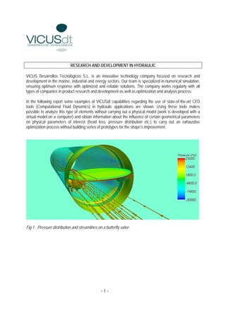
- 1. RESEARCH AND DEVELOPMENT IN HYDRAULIC VICUS Desarrollos Tecnológicos S.L. is an innovative technology company focused on research and development in the marine, industrial and energy sectors. Our team is specialized in numerical simulation, ensuring optimum response with optimized and reliable solutions. The company works regularly with all types of companies in product research and development as well as optimization and analysis process. In the following report some examples of VICUSdt capabilities regarding the use of state-of-the-art CFD tools (Computational Fluid Dynamics) in hydraulic applications are shown. Using these tools makes possible to analyze this type of elements without carrying out a physical model (work is developed with a virtual model on a computer) and obtain information about the influence of certain geometrical parameters on physical parameters of interest (head loss, pressure distribution etc.) to carry out an exhaustive optimization process without building series of prototypes for the shape’s improvement. Fig 1 . Pressure distribution and streamlines on a butterfly valve -1-
- 2. Fig 2 . Pressure distribution and streamlines on a butterfly valve. In the previous figures (Fig.1. and Fig 2.) the pressure distribution and the trajectory of fluid particles as they pass through a butterfly valve with inner diameter of about a meter are shown. Furthermore, the code allows extract integral values such as the head losses due to pressure and friction. The above problem takes into account a single-phase flow in which we only consider water, but in hydraulics there are other devices in which we have to consider and register the effect of air-water interaction and the evolution of the free surface. Routinely, VICUSdt performs studies of the behaviour of fluids with free surface and / or more phases in wave energy converters, moving tanks, breakwaters, etc. -2-
- 3. Fig. 3. Domain of study for a gate valve. Figure 3 shows in a virtual model the location of a gate valve at the end of a pipe. This type of analysis can identify changes in the distribution of pressure-forces on the mechanical components as a time function; this way, it is possible to use these loads for vibration analysis, fatigue, etc. In the same way we can identify areas which are susceptible to erosion, sedimentation, boundary layer detachment, vorticity, etc. -3-
- 4. Fig. 4. Initial time after the opening. Figure 4 corresponds to the first moments after the opening of the guillotine valve; In the image we can distinguish how the free surface separates the area occupied by the water from the area occupied by the air and how the air is "pushed" through the pipe. -4-
- 5. Fig. 5. Evolution of the free surface In Figure 5 it is shown that, as the surface of the water moves ahead, the forward direction of the air flowing through the pipe changes due to the suction induced by the water flow. -5-
- 6. Fig. 6. Virtual model of a “Howell-Bunger” valve. In Figure 6 we can see a virtual model of a valve type "Howell-Bunger" with a deflector head and ventilation system. Animations of the models described in the report can be found in the following links: http://www.vicusdt.com/videos/C013_V1.avi http://www.vicusdt.com/videos/C013_V2.avi http://www.vicusdt.com/videos/C013_V3.avi -6-
- 7. Fig. 7. Discharge of a “Howell-Bunger” valve. All these examples provide a measure of the applicability of CFD tools (Computational Fluid Mechanics) to study all types of hydraulic devices For more information: Adrián Sarasquete VICUS DESARROLLOS TECNOLOGICOS S.L. C/ Jacinto Benavente Nº 37 3º 36202 Vigo - Spain T: +34 886113547 M: +34 629384214 info@vicusdt.com www.vicusdt.com -7-