SlideShare a Scribd company logo
1 of 24
Method of Sections Erie Canal Lift Bridge – Main Street, Brockport, NY Statics ©2007 Coon  All Rights Reserved
Supports A  pinned  support can support a structure in two dimensions. A  roller  support can support a structure in only one dimension.
Static Determinacy Formula
Statically Indeterminate A truss is considered  statically indeterminate  when the static equilibrium equations are not sufficient to find the reactions on that structure.  There are simply too many unknowns. Try It Did you notice the two pinned connections?
Statically Determinate A truss is considered  statically determinate  when the static equilibrium equations can be used to find the reactions on that structure. Try It Is the truss statically determinate now?
Static Determinacy Example Each side of the main street bridge in Brockport, NY has 19 joints, 35 members and three reaction forces (pin and roller) making it a statically determinate truss.  What if these numbers were different?
Equilibrium Equations The sum of all forces in the X- direction is zero. The sum of all forces in the Y- direction is zero. The sum of the moments about a given point is zero.
Moment ary  Review ,[object Object],[object Object],[object Object],[object Object],[object Object],[object Object],RESISTANCE ARM L r EFFORT ARM L e F e EFFORT FORCE F r RESISTANCE FORCE A D C
Now lets replace the wheelbarrow with a truss. Likewise, joint  A  would be the fulcrum, the load is applied at joint  D , and the reaction at joint  C  is counteracting force  F D .  Remember the truss is in static equilibrium, therefore, all forces must sum to zero.  If we sum the moments about point  A , we can find the reaction force R CY  at point  C . Moment ary  Review RESISTANCE ARM L r EFFORT ARM L e F e EFFORT FORCE F r RESISTANCE FORCE 3’ 7’
Finding the Reaction Forces “For every action, there is an equal and opposite reaction” - Sir Isaac Newton
Using Moments to Find R CY A force that would cause a  clockwise  moment is  negative. A force that causes a  counterclockwise  moment is  positive. F D   is  negative  because it causes a clockwise moment. R CY  is  positive  because it causes a counterclockwise moment. 3’ 7’
Sum the Y Forces to Find R AY We know two out of the three forces acting in the Y-direction. By simply summing those forces together we can find the unknown reaction at point A. Please note that F B  is a shown as a  negative because of its direction. See  Cartesian coordinate system.
Sum the X Forces to Find R AX Because joint  A  is pinned, it could react to a force applied in the X-direction. However, Since the only load applied to  this truss ( F B ) has no X-component,  R AX   must be zero.
A B C D E F Load Load If you can solve a truss using the Method of Joints, you can solve a truss using the Method of Sections.
A B C D E F Load Load R AY R AX R FY Calculate Reaction Forces  R AX ,  R AY  &  R FY
A B C D E F Load Load R AY R AX R FY Let’s find the force in member CD. F CD known known known
A B C D E F Load Load R AY R AX R FY Cut across two or three members, but no more than three. known known known
A B C Load R AY R AX Treat this cut section as a RIDGID BODY. known known
A B C Load R AY R AX Assume the forces on cut members act as external forces on the cut F BD  Assumed Compression F CD  Assumed Tension F CE Assumed Tension known known
A B C Load R AY R AX Treat left section as a RIDGID BODY. F BD F CD F CE 3 unknowns  BD ,  CD X  &  BC 1 unknown  CD y  can be found 1 unknown  FE  can be found known known
The sum of all forces in the X- direction is zero. The sum of all forces in the Y- direction is zero. The sum of the moments about a given point is zero. Why can we only cut three members?
D E F Load R FY You could use the right side of the truss as well. Start by cutting through two or three members. F BD F CD F CE Assumed Compression Assumed Tension Assumed Compression known
D E F Load R FY You could use the right side of the truss as well. Start by cutting through two or three members. F BD F CD F CE 3 unknowns  BD ,  CD X  &  BC 1 unknown  CD y  can be found 1 unknown  FE  can be found known
Good Luck! Erie Canal Lift Bridge – Main Street, Brockport, NY ©2007 Coon  All Rights Reserved

More Related Content

What's hot

06-Strength of Double Angle Welded Tension Members (Steel Structural Design &...
06-Strength of Double Angle Welded Tension Members (Steel Structural Design &...06-Strength of Double Angle Welded Tension Members (Steel Structural Design &...
06-Strength of Double Angle Welded Tension Members (Steel Structural Design &...Hossam Shafiq II
 
Part-II: Seismic Analysis/Design of Multi-storied RC Buildings using STAAD.Pr...
Part-II: Seismic Analysis/Design of Multi-storied RC Buildings using STAAD.Pr...Part-II: Seismic Analysis/Design of Multi-storied RC Buildings using STAAD.Pr...
Part-II: Seismic Analysis/Design of Multi-storied RC Buildings using STAAD.Pr...Rahul Leslie
 
Shear and moment diagram
Shear and moment diagramShear and moment diagram
Shear and moment diagramIntishar Rahman
 
Portal and cantilever method
Portal and cantilever methodPortal and cantilever method
Portal and cantilever methodPrionath Roy
 
AS4100 Steel Design Webinar Worked Examples
AS4100 Steel Design Webinar Worked ExamplesAS4100 Steel Design Webinar Worked Examples
AS4100 Steel Design Webinar Worked ExamplesClearCalcs
 
Shear Force and Bending Moment Diagram
Shear Force and Bending Moment DiagramShear Force and Bending Moment Diagram
Shear Force and Bending Moment DiagramAmos David
 
Chapter 3-analysis of statically determinate trusses
Chapter 3-analysis of statically determinate trussesChapter 3-analysis of statically determinate trusses
Chapter 3-analysis of statically determinate trussesISET NABEUL
 
Guide for the design of crane supporting steel structures
Guide for the design of crane supporting steel structuresGuide for the design of crane supporting steel structures
Guide for the design of crane supporting steel structuresTimóteo Rocha
 
Worked examples - Wind webinar to AS1170.2 - ClearCalcs
Worked examples - Wind webinar to AS1170.2 - ClearCalcsWorked examples - Wind webinar to AS1170.2 - ClearCalcs
Worked examples - Wind webinar to AS1170.2 - ClearCalcsClearCalcs
 
Ch7 Box Girder Bridges (Steel Bridges تصميم الكباري المعدنية & Prof. Dr. Metw...
Ch7 Box Girder Bridges (Steel Bridges تصميم الكباري المعدنية & Prof. Dr. Metw...Ch7 Box Girder Bridges (Steel Bridges تصميم الكباري المعدنية & Prof. Dr. Metw...
Ch7 Box Girder Bridges (Steel Bridges تصميم الكباري المعدنية & Prof. Dr. Metw...Hossam Shafiq II
 

What's hot (20)

Lecture 1 design loads
Lecture 1   design loadsLecture 1   design loads
Lecture 1 design loads
 
06-Strength of Double Angle Welded Tension Members (Steel Structural Design &...
06-Strength of Double Angle Welded Tension Members (Steel Structural Design &...06-Strength of Double Angle Welded Tension Members (Steel Structural Design &...
06-Strength of Double Angle Welded Tension Members (Steel Structural Design &...
 
Structural engineering ii
Structural engineering iiStructural engineering ii
Structural engineering ii
 
Part-II: Seismic Analysis/Design of Multi-storied RC Buildings using STAAD.Pr...
Part-II: Seismic Analysis/Design of Multi-storied RC Buildings using STAAD.Pr...Part-II: Seismic Analysis/Design of Multi-storied RC Buildings using STAAD.Pr...
Part-II: Seismic Analysis/Design of Multi-storied RC Buildings using STAAD.Pr...
 
SFD BMD
SFD BMDSFD BMD
SFD BMD
 
Bolted joint design
Bolted joint designBolted joint design
Bolted joint design
 
Bolted Connection
Bolted ConnectionBolted Connection
Bolted Connection
 
Shear and moment diagram
Shear and moment diagramShear and moment diagram
Shear and moment diagram
 
Portal and cantilever method
Portal and cantilever methodPortal and cantilever method
Portal and cantilever method
 
AS4100 Steel Design Webinar Worked Examples
AS4100 Steel Design Webinar Worked ExamplesAS4100 Steel Design Webinar Worked Examples
AS4100 Steel Design Webinar Worked Examples
 
Shear Force and Bending Moment Diagram
Shear Force and Bending Moment DiagramShear Force and Bending Moment Diagram
Shear Force and Bending Moment Diagram
 
Design of column according ACI codes
Design of column according ACI codesDesign of column according ACI codes
Design of column according ACI codes
 
Chapter 3-analysis of statically determinate trusses
Chapter 3-analysis of statically determinate trussesChapter 3-analysis of statically determinate trusses
Chapter 3-analysis of statically determinate trusses
 
Guide for the design of crane supporting steel structures
Guide for the design of crane supporting steel structuresGuide for the design of crane supporting steel structures
Guide for the design of crane supporting steel structures
 
Worked examples - Wind webinar to AS1170.2 - ClearCalcs
Worked examples - Wind webinar to AS1170.2 - ClearCalcsWorked examples - Wind webinar to AS1170.2 - ClearCalcs
Worked examples - Wind webinar to AS1170.2 - ClearCalcs
 
influence line
 influence line influence line
influence line
 
Beam Deflection Formulae
Beam Deflection FormulaeBeam Deflection Formulae
Beam Deflection Formulae
 
Roof truss design
Roof truss designRoof truss design
Roof truss design
 
Ch7 Box Girder Bridges (Steel Bridges تصميم الكباري المعدنية & Prof. Dr. Metw...
Ch7 Box Girder Bridges (Steel Bridges تصميم الكباري المعدنية & Prof. Dr. Metw...Ch7 Box Girder Bridges (Steel Bridges تصميم الكباري المعدنية & Prof. Dr. Metw...
Ch7 Box Girder Bridges (Steel Bridges تصميم الكباري المعدنية & Prof. Dr. Metw...
 
Torsion
TorsionTorsion
Torsion
 

Viewers also liked

Viewers also liked (20)

Structural analysis (method of sections)
Structural analysis (method of sections)Structural analysis (method of sections)
Structural analysis (method of sections)
 
Calculating truss forces
Calculating truss forcesCalculating truss forces
Calculating truss forces
 
Trusses Sections
Trusses SectionsTrusses Sections
Trusses Sections
 
trusses
trussestrusses
trusses
 
Rc detailing-to-ec2
Rc detailing-to-ec2Rc detailing-to-ec2
Rc detailing-to-ec2
 
6161103 6.4 the method of sections
6161103 6.4 the method of sections6161103 6.4 the method of sections
6161103 6.4 the method of sections
 
Method of joints
Method of jointsMethod of joints
Method of joints
 
Truss
TrussTruss
Truss
 
Trusses Analysis Of Statically Determinate
Trusses Analysis Of Statically DeterminateTrusses Analysis Of Statically Determinate
Trusses Analysis Of Statically Determinate
 
Shear Force And Bending Moment Diagram For Frames
Shear Force And Bending Moment Diagram For FramesShear Force And Bending Moment Diagram For Frames
Shear Force And Bending Moment Diagram For Frames
 
Shear & Bending Moment Diagram
Shear & Bending Moment DiagramShear & Bending Moment Diagram
Shear & Bending Moment Diagram
 
Trusses
TrussesTrusses
Trusses
 
Determinate structures
 Determinate structures Determinate structures
Determinate structures
 
PPT OF TRUSSES
PPT OF TRUSSESPPT OF TRUSSES
PPT OF TRUSSES
 
Structures and Materials- Section 1 Statics
Structures and Materials- Section 1 StaticsStructures and Materials- Section 1 Statics
Structures and Materials- Section 1 Statics
 
Presentation1
Presentation1Presentation1
Presentation1
 
Week 4
Week 4Week 4
Week 4
 
Bs 1881 112 1983
Bs 1881 112 1983Bs 1881 112 1983
Bs 1881 112 1983
 
Practicar metodos
Practicar metodosPracticar metodos
Practicar metodos
 
Ce 382 l5 truss structures
Ce 382 l5   truss structuresCe 382 l5   truss structures
Ce 382 l5 truss structures
 

Similar to Trusses Method Of Sections

Forces acting on the beam with shear force & bending moment
Forces acting on the beam with shear force & bending momentForces acting on the beam with shear force & bending moment
Forces acting on the beam with shear force & bending momentTaral Soliya
 
Step by step Engineering Mechanics updated
Step by step Engineering Mechanics updatedStep by step Engineering Mechanics updated
Step by step Engineering Mechanics updatedProf. S.Rajendiran
 
module 3 (Mechanics)
module 3 (Mechanics)module 3 (Mechanics)
module 3 (Mechanics)Nexus
 
03_FreeBodyDiagrams.pdf
03_FreeBodyDiagrams.pdf03_FreeBodyDiagrams.pdf
03_FreeBodyDiagrams.pdfAdilsoncj2
 
Analysis of plane truss unit 5
Analysis of plane  truss unit 5Analysis of plane  truss unit 5
Analysis of plane truss unit 5Parimal Jha
 
Engineering Mechanics First Year
Engineering Mechanics First YearEngineering Mechanics First Year
Engineering Mechanics First YearEkeeda
 
Forces 7
Forces 7Forces 7
Forces 7Ekeeda
 
Coplanar forces equilibrium
Coplanar forces equilibriumCoplanar forces equilibrium
Coplanar forces equilibriumEkeeda
 
3. coplanar forces equilibrium
3. coplanar forces equilibrium3. coplanar forces equilibrium
3. coplanar forces equilibriumEkeeda
 
Step by step Engineering Mechanics updated
Step by step Engineering Mechanics updatedStep by step Engineering Mechanics updated
Step by step Engineering Mechanics updatedProf. S.Rajendiran
 
Lesson 04, shearing force and bending moment 01
Lesson 04, shearing force and bending moment 01Lesson 04, shearing force and bending moment 01
Lesson 04, shearing force and bending moment 01Msheer Bargaray
 
moments couples and force couple systems by ahmad khan
moments couples and force couple systems by ahmad khanmoments couples and force couple systems by ahmad khan
moments couples and force couple systems by ahmad khanSelf-employed
 
Trusses Joints
Trusses JointsTrusses Joints
Trusses JointsAmr Hamed
 

Similar to Trusses Method Of Sections (20)

Forces acting on the beam with shear force & bending moment
Forces acting on the beam with shear force & bending momentForces acting on the beam with shear force & bending moment
Forces acting on the beam with shear force & bending moment
 
Step by step Engineering Mechanics updated
Step by step Engineering Mechanics updatedStep by step Engineering Mechanics updated
Step by step Engineering Mechanics updated
 
module 3 (Mechanics)
module 3 (Mechanics)module 3 (Mechanics)
module 3 (Mechanics)
 
03_FreeBodyDiagrams.pdf
03_FreeBodyDiagrams.pdf03_FreeBodyDiagrams.pdf
03_FreeBodyDiagrams.pdf
 
Sf and bm
Sf and bmSf and bm
Sf and bm
 
Analysis of plane truss unit 5
Analysis of plane  truss unit 5Analysis of plane  truss unit 5
Analysis of plane truss unit 5
 
Engineering Mechanics First Year
Engineering Mechanics First YearEngineering Mechanics First Year
Engineering Mechanics First Year
 
Forces 7
Forces 7Forces 7
Forces 7
 
Coplanar forces equilibrium
Coplanar forces equilibriumCoplanar forces equilibrium
Coplanar forces equilibrium
 
3. coplanar forces equilibrium
3. coplanar forces equilibrium3. coplanar forces equilibrium
3. coplanar forces equilibrium
 
Are pocket structures
Are pocket structuresAre pocket structures
Are pocket structures
 
Are pocket structures
Are pocket structuresAre pocket structures
Are pocket structures
 
Are pocket structures
Are pocket structuresAre pocket structures
Are pocket structures
 
Step by step Engineering Mechanics updated
Step by step Engineering Mechanics updatedStep by step Engineering Mechanics updated
Step by step Engineering Mechanics updated
 
Lesson 04, shearing force and bending moment 01
Lesson 04, shearing force and bending moment 01Lesson 04, shearing force and bending moment 01
Lesson 04, shearing force and bending moment 01
 
moments couples and force couple systems by ahmad khan
moments couples and force couple systems by ahmad khanmoments couples and force couple systems by ahmad khan
moments couples and force couple systems by ahmad khan
 
Chapter 19(statically indeterminate beams continuous beams)
Chapter 19(statically indeterminate beams continuous beams)Chapter 19(statically indeterminate beams continuous beams)
Chapter 19(statically indeterminate beams continuous beams)
 
Truss
TrussTruss
Truss
 
Ch3
Ch3Ch3
Ch3
 
Trusses Joints
Trusses JointsTrusses Joints
Trusses Joints
 

More from Amr Hamed

B Ending Moments And Shearing Forces In Beams2
B Ending Moments And Shearing Forces In Beams2B Ending Moments And Shearing Forces In Beams2
B Ending Moments And Shearing Forces In Beams2Amr Hamed
 
B Ending Moments And Shearing Forces In Beams2
B Ending Moments And Shearing Forces In Beams2B Ending Moments And Shearing Forces In Beams2
B Ending Moments And Shearing Forces In Beams2Amr Hamed
 
Trusses Joints 2
Trusses Joints 2Trusses Joints 2
Trusses Joints 2Amr Hamed
 
Trusses Intro
Trusses IntroTrusses Intro
Trusses IntroAmr Hamed
 
Trusses Frame Machines Analysis
Trusses Frame Machines AnalysisTrusses Frame Machines Analysis
Trusses Frame Machines AnalysisAmr Hamed
 
Shear Force And Bending Moment In Beams22
Shear Force And Bending Moment In Beams22Shear Force And Bending Moment In Beams22
Shear Force And Bending Moment In Beams22Amr Hamed
 
Shear Force And Bending Moment In Beams
Shear Force And Bending Moment In BeamsShear Force And Bending Moment In Beams
Shear Force And Bending Moment In BeamsAmr Hamed
 
Shear And Moment Diagrams
Shear And Moment DiagramsShear And Moment Diagrams
Shear And Moment DiagramsAmr Hamed
 
Lecture 20 (Sfd And Bmd)
Lecture 20 (Sfd And Bmd)Lecture 20 (Sfd And Bmd)
Lecture 20 (Sfd And Bmd)Amr Hamed
 
Shear and Bending Moment in Beams
Shear and Bending Moment in BeamsShear and Bending Moment in Beams
Shear and Bending Moment in BeamsAmr Hamed
 
Shear Force And Bending Moment Diagram For Beams
Shear Force And Bending Moment Diagram For BeamsShear Force And Bending Moment Diagram For Beams
Shear Force And Bending Moment Diagram For BeamsAmr Hamed
 
Shear and Bending Moment in Beams
Shear and Bending Moment in BeamsShear and Bending Moment in Beams
Shear and Bending Moment in BeamsAmr Hamed
 

More from Amr Hamed (15)

B Ending Moments And Shearing Forces In Beams2
B Ending Moments And Shearing Forces In Beams2B Ending Moments And Shearing Forces In Beams2
B Ending Moments And Shearing Forces In Beams2
 
Wk1 2 Beams
Wk1 2 BeamsWk1 2 Beams
Wk1 2 Beams
 
B Ending Moments And Shearing Forces In Beams2
B Ending Moments And Shearing Forces In Beams2B Ending Moments And Shearing Forces In Beams2
B Ending Moments And Shearing Forces In Beams2
 
Wk1 2 Beams
Wk1 2 BeamsWk1 2 Beams
Wk1 2 Beams
 
Trusses Joints 2
Trusses Joints 2Trusses Joints 2
Trusses Joints 2
 
Trusses Intro
Trusses IntroTrusses Intro
Trusses Intro
 
Trusses Frame Machines Analysis
Trusses Frame Machines AnalysisTrusses Frame Machines Analysis
Trusses Frame Machines Analysis
 
Shear Force And Bending Moment In Beams22
Shear Force And Bending Moment In Beams22Shear Force And Bending Moment In Beams22
Shear Force And Bending Moment In Beams22
 
Shear Force And Bending Moment In Beams
Shear Force And Bending Moment In BeamsShear Force And Bending Moment In Beams
Shear Force And Bending Moment In Beams
 
5 Beams[1]
5 Beams[1]5 Beams[1]
5 Beams[1]
 
Shear And Moment Diagrams
Shear And Moment DiagramsShear And Moment Diagrams
Shear And Moment Diagrams
 
Lecture 20 (Sfd And Bmd)
Lecture 20 (Sfd And Bmd)Lecture 20 (Sfd And Bmd)
Lecture 20 (Sfd And Bmd)
 
Shear and Bending Moment in Beams
Shear and Bending Moment in BeamsShear and Bending Moment in Beams
Shear and Bending Moment in Beams
 
Shear Force And Bending Moment Diagram For Beams
Shear Force And Bending Moment Diagram For BeamsShear Force And Bending Moment Diagram For Beams
Shear Force And Bending Moment Diagram For Beams
 
Shear and Bending Moment in Beams
Shear and Bending Moment in BeamsShear and Bending Moment in Beams
Shear and Bending Moment in Beams
 

Trusses Method Of Sections

  • 1. Method of Sections Erie Canal Lift Bridge – Main Street, Brockport, NY Statics ©2007 Coon All Rights Reserved
  • 2. Supports A pinned support can support a structure in two dimensions. A roller support can support a structure in only one dimension.
  • 4. Statically Indeterminate A truss is considered statically indeterminate when the static equilibrium equations are not sufficient to find the reactions on that structure. There are simply too many unknowns. Try It Did you notice the two pinned connections?
  • 5. Statically Determinate A truss is considered statically determinate when the static equilibrium equations can be used to find the reactions on that structure. Try It Is the truss statically determinate now?
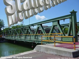
  • 6. Static Determinacy Example Each side of the main street bridge in Brockport, NY has 19 joints, 35 members and three reaction forces (pin and roller) making it a statically determinate truss. What if these numbers were different?
  • 7. Equilibrium Equations The sum of all forces in the X- direction is zero. The sum of all forces in the Y- direction is zero. The sum of the moments about a given point is zero.
  • 8.
  • 9. Now lets replace the wheelbarrow with a truss. Likewise, joint A would be the fulcrum, the load is applied at joint D , and the reaction at joint C is counteracting force F D . Remember the truss is in static equilibrium, therefore, all forces must sum to zero. If we sum the moments about point A , we can find the reaction force R CY at point C . Moment ary Review RESISTANCE ARM L r EFFORT ARM L e F e EFFORT FORCE F r RESISTANCE FORCE 3’ 7’
  • 10. Finding the Reaction Forces “For every action, there is an equal and opposite reaction” - Sir Isaac Newton
  • 11. Using Moments to Find R CY A force that would cause a clockwise moment is negative. A force that causes a counterclockwise moment is positive. F D is negative because it causes a clockwise moment. R CY is positive because it causes a counterclockwise moment. 3’ 7’
  • 12. Sum the Y Forces to Find R AY We know two out of the three forces acting in the Y-direction. By simply summing those forces together we can find the unknown reaction at point A. Please note that F B is a shown as a negative because of its direction. See Cartesian coordinate system.
  • 13. Sum the X Forces to Find R AX Because joint A is pinned, it could react to a force applied in the X-direction. However, Since the only load applied to this truss ( F B ) has no X-component, R AX must be zero.
  • 14. A B C D E F Load Load If you can solve a truss using the Method of Joints, you can solve a truss using the Method of Sections.
  • 15. A B C D E F Load Load R AY R AX R FY Calculate Reaction Forces R AX , R AY & R FY
  • 16. A B C D E F Load Load R AY R AX R FY Let’s find the force in member CD. F CD known known known
  • 17. A B C D E F Load Load R AY R AX R FY Cut across two or three members, but no more than three. known known known
  • 18. A B C Load R AY R AX Treat this cut section as a RIDGID BODY. known known
  • 19. A B C Load R AY R AX Assume the forces on cut members act as external forces on the cut F BD Assumed Compression F CD Assumed Tension F CE Assumed Tension known known
  • 20. A B C Load R AY R AX Treat left section as a RIDGID BODY. F BD F CD F CE 3 unknowns BD , CD X & BC 1 unknown CD y can be found 1 unknown FE can be found known known
  • 21. The sum of all forces in the X- direction is zero. The sum of all forces in the Y- direction is zero. The sum of the moments about a given point is zero. Why can we only cut three members?
  • 22. D E F Load R FY You could use the right side of the truss as well. Start by cutting through two or three members. F BD F CD F CE Assumed Compression Assumed Tension Assumed Compression known
  • 23. D E F Load R FY You could use the right side of the truss as well. Start by cutting through two or three members. F BD F CD F CE 3 unknowns BD , CD X & BC 1 unknown CD y can be found 1 unknown FE can be found known
  • 24. Good Luck! Erie Canal Lift Bridge – Main Street, Brockport, NY ©2007 Coon All Rights Reserved