Long span structures
•
212 likes•123,164 views

This presentation describes various types of long span structures that can be designed in accordance to the various needs.

Recommended
More Related Content
What's hot
What's hot (20)
Viewers also liked
Viewers also liked (20)
Similar to Long span structures
Similar to Long span structures (20)
More from Aroh Thombre
Recently uploaded
Recently uploaded (20)
Long span structures
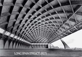
- 2. LONG SPAN STRUCTURE’S Structures with span larger than 15-20 meters are regarded to as Long Span Structures. For Such structures span is unable to be achieved with ordinary R.C.C. construction. Generally long spans result in flexible, column-free internal spaces, reduces substructure costs and time to erect the structure. *DEFINATION *COMMON STRUCTURAL SYSTEMS FOR LONG SPAN STRUCTURES Long span Beams Long span Trusses Long span Roof structures • Tensile structures • Folded Plates • Shell structures • Portal Frames
- 3. LONG SPAN BEAMS The use of long span beams results in a range of benefits, including flexible, column-free internal spaces, reduced foundation costs, and reduced steel erection times. Many long span solutions are also well adapted to facilitate the integration of services without increasing the overall floor depth. Types of Long Span Beams • Parallel Beam Approach • Composite Beams with Web Openings • Cellular Composite Beams • Tapered Girders • Haunched Composite Beams
- 4. LONG SPAN BEAMS *Parallel Beam Approach The parallel beam approach is effective for spans up to around 20 m. Floor grids comprise two layers of fully continuous beams running in orthogonal directions. Services running in either direction can be integrated within these two layers, so that services passing in any direction can be accommodated within the structural floor depth. A further benefit is that, being fully continuous, the depth of the beams themselves is reduced without incurring the expense and complexity of rigid, full strength connections.
- 5. LONG SPAN BEAMS *Composite Beams with Web Openings: Web openings are typically formed in beams to allow services to pass through the beam. This enables the structural and service zones to occupy the same space, thereby reducing the effective overall depth of floor construction for a given spanning capability. Openings may also be formed for aesthetic reasons, for instance with cambered beams used to support a roof. Composite beams with web openings have been shown to be a cost effective solution for spans in the range 15-30m.
- 6. LONG SPAN BEAMS *Cellular Composite Beams: Cellular beams are a form of beam with multiple regular web openings , formed by splitting two rolled sections longitudinally, to form two Tee sections. The two Tees, which may not come from the same donor section are then welded together to form an I-section with web openings which have a characteristic shape (normally, but not necessarily, circular).
- 7. LONG SPAN BEAMS *Tapered Girders: Tapered girders can be a cost effective solution in the span range 15 m to 25 m. They are another solution that allows services to be accommodated within the structural floor zone. The depth of the girder increases towards mid-span, where applied moments are greatest, and thereby facilitating hanging services under the shallower regions near the beam supports. It is also possible to form web openings in tapered girders in regions of low shear, towards mid-span. These provide more options for service integration.
- 8. LONG SPAN BEAMS *Haunched composite beams: Haunches may be added at the ends of a composite beam to provide moment continuity. The stiffness and strength of the connections mean that the rest of the span can be shallower (the bending moment diagram is 'lifted' and the effective stiffness of the beam substantially increased), and services passed under it. In buildings where the services are likely to need frequent replacement (for example in hospitals), hanging the services under the beams rather than passing them through holes in the webs, or through a truss, can be advantageous. Spans in excess of 20-30 m can readily be achieved.
- 9. LONG SPAN TRUSSES: A truss is essentially a triangulated system of straight interconnected structural elements. The most common use of trusses is in buildings, where support to roofs, the floors and internal loading such as services and suspended ceilings, are readily provided. The main reasons for using trusses are: • Long span • Lightweight • Reduced deflection (compared to plain members) • Opportunity to support considerable loads. Types of Long Span Trusses: • Pratt Truss • Warren Truss • North Light Truss • Saw Tooth Truss • Fink Truss
- 10. LONG SPAN TRUSSES: Pratt Truss: Pratt trusses are commonly used in long span buildings ranging from 20 to 75 m in span. In a conventional Pratt truss, diagonal members are in tension for gravity loads. This type of truss is used where gravity loads are predominant. An alternative Pratt truss is shown where the diagonal members are in tension for uplift loads. This type of truss is used where uplift loads are predominant, which may be the case in open buildings such It is possible to add secondary members to: •Create intermediate support points for applied loads •Limit the buckling length of members in compression. as Aircraft hangers.
- 11. LONG SPAN TRUSSES: Warren Truss: In this type of truss, diagonal members are alternatively in tension and in compression. The Warren truss has equal length compression and tension web members, and fewer members than a Pratt truss. A modified Warren truss may be adopted where additional members are introduced to provide a node at (for example) purlin locations. Warren trusses are commonly used in long span buildings ranging from 20 to 100 m in span. This type of truss is also used for the horizontal truss of gantry/crane girders. Warren Truss
- 12. LONG SPAN TRUSSES: North Light Truss: North light trusses are traditionally used for short spans in industrial workshop-type buildings. They allow maximum benefit to be gained from natural lighting by the use of glazing on the steeper pitch which generally faces north or north-east to reduce solar gain. On the steeper sloping portion of the truss, it is typical to have a truss running perpendicular to the plane of the North Light truss, to provide large column-free spaces. Fink Truss: The Fink truss offers economy in terms of steel weight for short-span high-pitched roofs as the members are subdivided into shorter elements. There are many ways of arranging and subdividing the chords and internal members. This type of truss is commonly used to construct roofs in houses.
- 13. LONG SPAN TRUSSES: General Geometry: For efficient structural performance, the ratio of span to truss depth should be chosen in the range 10 to 15. The architectural design of the building determines its external geometry and governs the slope(s) given to the top chord of the truss. The intended use of the internal space can lead either to the choice of a horizontal bottom chord. For an efficient layout of the truss members between the chords, the following is advisable: •The inclination of the diagonal members in relation to the chords should be between 35° and 55° •Point loads should only be applied at nodes •The orientation of the diagonal members should be such that the longest members are subject to tension (the shorter ones being subject to compression).
- 14. LONG SPAN TRUSSES: Types of Truss Member sections: Many solutions are available. Choice of members depends on the magnitude of the internal forces, ease of connections between members, aesthetics and any necessity to connect prefabricated truss sections on site. When selecting members, the out-of-plane buckling resistance will be important, together with resistance under reversed loading, for example, uplift. For large trusses and heavy loads, typically found in transfer trusses in buildings, members may be rolled sections. Nodes are usually welded. Any necessary connections are completed with bolted splices within the length between nodes.
- 15. LONG SPAN TRUSSES: Types of Connections: For all the types of member sections, it is possible to design either bolted or welded connections. Generally in steelwork construction, bolted site splices are preferred to welded splices for economy and speed of erection. Where bolted connections are used, it is necessary to evaluate the consequences of 'slack' in connections. In order to reduce these consequences (typically, the increase of the deflections), solutions are available such as use of preloaded bolts. Hollow sections are typically connected by welding whilst open sections are connected by bolting or welding, which will usually involve the use of gusset plates.
- 16. LONG SPAN TRUSSES: Examples: Gallery of Machines Paris (span=112m height=45m)
- 17. LONG SPAN TRUSSES: Examples: Hong Kong Convention and Exhibition Center (span= 80m)
- 18. LONG SPAN TRUSSES: Examples: Hong Kong Stadium (span=100m and 60m)
- 19. LONG ROOF STRUCTURES: Portal Frames: A portal frame building comprises a series of transverse frames braced longitudinally. The primary steelwork consists of columns and rafters, which form portal frames, and bracing. The end frame (gable frame) can be either a portal frame or a braced arrangement of columns and rafters. The light gauge secondary steelwork consists of side rails for walls and purlins for the roof. The secondary steelwork supports the building envelope, but also plays an important role in restraining the primary steelwork. Portal frames can span from 20-100m.