1. PIEZOELECTRIC EFFECT
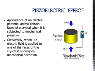
Appearance of an electric
potential across certain
faces of a crystal when it is
subjected to mechanical
pressure
Conversely, when an
electric field is applied to
one of the faces of the
crystal it undergoes
mechanical distortion.
2. PieZOELECTRIC PHENOMENON
In 1880 Curie brothers discovered the
direct piezoelectric effect in certain
solid crystalline dielectric substances
such as quartz.
The word piezo originates from the
Greek word “piezein”, which means “to
press”
3. MATERIALS USED
The material that show significant and useful
piezoelectric effect fall under three main groups:
1. Natural, Eg: Quartz, Rochelle salt
2. Synthetic, Eg: Lithium Sulphate, Ammonium
Dihydrogen Phosphate
3. Polarized Ferroelectric Crystals, Eg: Barium
Titanate, Lead Zirconate-Titanate
4. • Because of their natural asymmetric structure,
the crystal materials other than ferroelectric
crystals exhibit piezoelectric effect without
further processing.
• However for ferroelectric crystals, they need to
undergo certain processing.
• They must be artificially polarized by applying a
strong electric field to the material, while it is
heated to a temperature above the Curie point
of the material. They are then slowly cooled with
the field still applied. When external field is
removed they have a remnant polarization
which allows them to exhibit the piezoelectric
effect.
5.
6. PIEZOELECTRIC TRANSDUCERS
There are two families of
constants which are used
to describe the piezoelectric
effect:
• g constant
• d constant
These are written as gij and dij
Where,
i= direction of electric effect
j= direction of mechanical effect
7. • g constant is defined as:
g33=(field produced in direction 3)/(stress applied for direction 3)
V/c
F/ab
• d constant is defined as:
d33=(charge generated in direction 3)/(force applied in direction 3)
q/F
8. Piezoelectric crystal can be represented as a charge
generator q in parallel with a capacitance CN
Ra
9. Rs=Resistance of the crystal
Cs=Capacitance of the crystal
Cc=Cable capacitance
Ca= Capacitance of the amplifier
Ra= resistance of the amplifier
11. Vo = iR = (dq/dt-C dVo/dt)R
Or, RC dVo/dt +Vo = Rdq/dt
By Laplace Transformation,
Vo(s)/q(s) = Rs/(RCs+1)
12. We know that, q = d*F
Therefore,
Vo(s)/F(s) = dRs/(RCs+1)
Vo(s)/F(s) = (d/C)RCs/(RCs+1)
Vo(s)/F(s) = (d/C)τ/(τs+1)
• The above represents the transfer
function.
13. • It is not possible to measure any
static force with this circuit.
• Static Sensitivity (d/C) will change
with the change in any of the
values of Cc or Ca.
• For this reason we use Charge
Amplifier.
14.
15. From circuit Analysis:
i = dq/dt = -Vo/Rf – Cf dVo/dt
Or, RfCf dVo/dt + Vo = -Rf dq/dt
Or, Vo(s)/q(s) = -Rfs/(RfCfs+1)
16. Vo(s)/F(s) = -(d/Cf)RfCfs/(RfCfs+1)
Vo(s)/F(s) = -(d/Cf)τfs/(τfs+1)
Where, τf=RfCf
• The above circuit also cannot measure static
force but it removes dependencies on cable
capacitance and resistances.
18. Applied Piezo: Applications
Piezoelectric materials are used in
numerous applications.
The direct piezoelectric effect is used in
e.g.
generators (e.g. gas igniters)
sensors (e.g. accelerometers, pressure
sensors)
switches (e.g. in control panels)
ultrasonic transducers (e.g. in medical
imaging)
19. The indirect piezoelctric effect is used in e.g.
actuators (for micropositioning, micropumps,
microvalves)
motors (e.g. inchworm motors, SAW motors)
speakers, buzzers (e.g. in mobile phones)
ultrasonic transducers (e.g. sonar)
A combination of the direct and the indirect
piezoelectric effect is found in
active vibration control (e.g. active damping)
smart structures (e.g. active shape control)
voltage transformers
quartz oscillators (e.g. for timing in
microelectronics)
20.
21.
22. Principle of Operation
Physical Setup: Piezoelectric Material
Sandwiched Between Base and
Resonant Mass - Also Shear, Bender
Motion Causes Resonant Mass to
Move, Force to Move Mass Is
Transmitted Through Piezoelectric
Material (F = ma)
Compression/Tension or Shear of
Piezoelectric Material Causes Charge
Buildup Proportional to Acceleration
Equivalent Electric Circuit
Measures Capacitance
Depends On Cable
23. Characteristics of Accelerometers
Dynamic Range: Should Be Able to
Measure Low and High Level Vibration
Lower Limit is Noise
Upper Limit is Set By Accelerometer
Frequency Range: Should Be Able to
Measure Across a Broad Bandwidth
Accelerometer is SDOF system w/
Frequency Response
Physical Dimensions
Weight
Size
25. Piezo Electric Generator or Oscillator
Principle : Inverse piezo electric effect
If mechanical pressure is applied to one pair of
opposite faces of certain crystals like quartz, equal
and opposite electrical charges appear across its
other faces.This is called as piezo-electric effect.
The converse of piezo electric effect is also true.
If an electric field is applied to one pair of faces, the
corresponding changes in the dimensions of the
other pair of faces of the crystal are produced.This
is known as inverse piezo electric effect or
electrostriction.
27. The quartz crystal is placed between two metal
plates A and B.
The plates are connected to the primary (L3) of
a transformer which is inductively coupled to
the electronics oscillator.
The electronic oscillator circuit is a base tuned
oscillator circuit.
The coils L1 and L2 of oscillator circuit are
taken from the secondary of a
transformer T.
The collector coil L2 is inductively coupled
to base coil L1.
The coil L1 and variable capacitor C1 form
the tank circuit of the oscillator.
28. Working
When H.T. battery is switched on, the oscillator produces high
frequency alternating voltages with a frequency.
1
L C
1 1 2
f
Due to the transformer action, an oscillatory e.m.f. is induced in the coil L3. This high
frequency alternating voltages are fed on the plates A and B.
Inverse piezo-electric effect takes place and the crystal contracts and expands
alternatively.The crystal is set into mechanical vibrations.
The frequency of the vibration is given by
n =
Y
P
2
l
where P = 1,2,3,4 … etc. for fundamental, first
over tone, second over tone etc.,
Y = Young’s modulus of the crystal and
ρ = density of the crystal
29. The variable condenser C1 is adjusted such that the frequency of the
applied AC voltage is equal to the natural frequency of the quartz crystal,
and thus resonance takes place.
The vibrating crystal produces longitudinal ultrasonic waves of large
amplitude.
PH01
01
UNIT
1
LECTU
RE 6
29
31. One of the most important features of any
oscillator is its frequency stability, or in other
words its ability to provide a constant
frequency output under varying load
conditions. Some of the factors that affect the
frequency stability of an oscillator generally
include: variations in temperature, variations
in the load as well as changes to its DC power
supply voltage to name a few.
32. To obtain a very high level of oscillator stability a Quartz Crystal is
generally used as the frequency determining device to produce
another types of oscillator circuit known generally as a Quartz
Crystal Oscillator, (XO).
When a voltage source is applied to a small thin piece of quartz
crystal, it begins to change shape producing a characteristic
known as the Piezo-electric effect. This Piezo-electric Effect is the
property of a crystal by which an electrical charge produces a
mechanical force by changing the shape of the crystal and vice
versa, a mechanical force applied to the crystal produces an
electrical charge.
33. The quartz crystal used in a Quartz Crystal Oscillator is a
very small, thin piece or wafer of cut quartz with the two
parallel surfaces metallised to make the required
electrical connections. The physical size and thickness of a
piece of quartz crystal is tightly controlled since it affects
the final or fundamental frequency of oscillations. The
fundamental frequency is called the crystals
“characteristic frequency”.
Then once cut and shaped, the crystal can not be used at
any other frequency. In other words, its size and shape
determines its fundamental oscillation frequency.
34. The crystals characteristic or resonant frequency
is inversely proportional to its physical thickness
between the two metallised surfaces. A
mechanically vibrating crystal can be represented
by an equivalent electrical circuit consisting of
low resistance, large inductance and
small capacitance as shown below.
35.
36.
37. Limitations
Each piezoelectric material has a particular
operating limit for temperature, voltage, and
stress. The particular chemical composition of the
material determines the limits. Operating a
material outside of these limitations may cause
partial or total depolarization of the material, and
a diminishing or loss of piezoelectric properties.
38. Temperature Limitations
As the operating temperature increases, piezoelectric performance of a
material decreases, until complete and permanent depolarization occurs at
the material's Curie temperature.
The Curie point is the absolute maximum exposure temperature for any
piezoelectric ceramic. Each ceramic has its own Curie point. When the
ceramic element is heated above the Curie point, all piezoelectric properties
are lost. In practice, the operating temperature must be substantially below
the Curie point.
The material's temperature limitation decreases with greater continuous
operation or exposure. At elevated temperatures, the ageing process
accelerates, piezoelectric performance decreases and the maximum safe
stress level is reduced.
39. Voltage Limitations
A piezoelectric ceramic can be depolarized by a strong electric field
with polarity opposite to the original poling voltage.
The limit on the field strength is dependent on the type of
material, the duration of the application, and the operating
temperature. The typical operating limit is between 500V/mm and
1 000V/mm for continuous application.
It should be noted that alternating fields can have the same affect
during the half cycle which is opposite to the poling direction.
40. Mechanical Stress Limitations
High mechanical stress can depolarize a piezoelectric ceramic. The
limit on the applied stress is dependent on the type of ceramic
material, and duration of the applied stress.
For dynamic stress (impact ignition) the limit is less severe;
materials with higher energy output (high g constant) can be
used.
For impact applications, the material behaves quasi statically
(non-linear) for pulse durations of a few milliseconds or more.
When the pulse duration approaches a microsecond, the
piezoelectric effect becomes linear, due to the short application
time compared to the relaxation time of the domains.
41.
42.
43.
44. ADVANTAGES
1. HIGH FREQUENCY RESPONSE
The parameter changing at very high speeds
can be sensed easily.
2.HIGH TRANSIENT RESPONSE
Even the events of microsecond durations can
be detected.
46. DISADVANTAGES
It is not suitable for measurement in
static conditions.
The output may vary according to the
variation in temperature of the
crystal.
It is very difficult to give the desired
shape to the crystals with sufficient
strength
47. Since the device operates with small
electric charge, high impedance cable
is needed for electrical interface. So
they have to be connected to the
amplifier and the auxiliary circuit
,which have potential to cause errors
in the measurement.
Output is low.
49. Electric Field
Interaction of charges.
Electric field , E = F/q ,
where F=force experienced by the charged particle of charge
q.
50. Strain
Ratio of change in length by original length.
Dimensionless measure.
Material property of all elastic solids , Young’s
modulus is defined as stiffness of material.
Y=(L/a)*(F/dL)
Used to determine equivalence spring constant of
rod/plate of material i.e. in contact with piezo
actuator.
51. Tensile Strength
Stress measured in Newtons per m^2 at
which the sample of solid material will
break from tension.
Damping: general tendency of vibrating
materials or structures to loose some
elastic energy to internal heating or
external friction.
52. Why Piezoelectricity?
Some atomic lattice structures have
essential unit or cell i.e. a cubic or
rhomboid cage made of atoms and this
cage holds a single semi mobile ion which
has several stable quantum position states
inside the cell.
They change by deformation or by
application of electric field.
53. Poling and Depoling
Piezoceramic material is subjected to a high
electric field for a short period of time to force the
randomly oriented dipoles into alignment. This
alignment of application of high voltage is called
poling.
If electric field is applied in opposite direction, it
exerts a dislodging stress on micro dipoles .Low
level applied field result in no permanent change
in polarisation.
54. Piezoactuators at cryogenic temperatures
Piezoelectric effect is due to interatomic electric
fields and their electric effect is not affected by
temperature at all. Quantitatively the piezo
coupling of most piezo ceramics decrease as
temperature decreases.
55. Pyroelectric effect
Tendency of some materials to exhibit a
change in internal electric polarisation
state in response to change in
temperature.
56. Handling and preparation of piezo ceramics
Shaping to required size : Using a diamond saw ,razor blade OR straight edge to score a
piezo surface and then making a controlled break.
Attaching /bonding a piezoceramic sheet :good quality temporary bonds maybe made with
cyanoacrylate. E.g. :superglue.
An added benefit of this bond is that it easily achieves electrical contact.
The time span of bond is application dependent.
Should be handled with great care. Dropping them always results in shattered parts. This
can be avoided by bondage with metal shim. The shim can be accessed by supporting the
bender underneath by using a milling machine. Water is used as a lubricant.
Hooking up a bender element :this depends on how the two ceramic plates are polarised.
57. Properties
Etching of electrode :Chemically etch, sand
blast , laser ablate or sand paper the
electrode.
Elasticity :A sheet can be stretched to strain
of approx. 500 micro strain in regular use.
Repoling of sheet : For a 5H material an
electric field of 50-60 V/mil will restore
nearly all lost polarisation.
58. Applications
Frequency limit : No inherent frequency limit. Determined by resonances associated
by shape and size of transducer designed.
Highest voltage : 300volts
Mechanical power obtained : One standard PSI -5A sheet used as an extender can
do 0.00035 joules of work on the outside world in a quasi static cycle.
Electrical power : Theoretical- 9 watts
Practical – 3.6mWatts
Static and dynamic application : Not suitable for static due to charge leakage. Used
for transient force measurements lasting less than 0.1 s.
Expected fatigue : Dependent on mounting and voltages.
Detection of vibrations: Almost any size or shape can pick signals as when fastened
somewhere on a machinery.
59. As a strain gauge: Most sensitive and self powered.
Repeatable outputs from piezo : Outputs from piezo are generally
very repeatable and stable. Hysteresis and creep affects cause non
repeatable motion if the cycle time is changed.
Temperature effects : Changes in temperature leads to voltage
change across electrodes due to pyro electic properties of piezo
electric.
60. Piezo technology
Found in watch beepers, smoke detector alarms ,fish finders, cigarette lighters and
many gas grill igniters.
Vibration cancellation : Two sheets can be bonded directly to the surface of a
structure close to one another at a site were unwanted bending occurs. The output
from strain sensor is fed into a smart box, which in turn controls a power amplifier
which drives the other piezo ceramic sheet. Finally the resulting mechanical
contractions of the second piezo sheet injects a vibration into structure which is equal
and opposite to initially detected so that the next vibration is cancelled.
Magnetic technology is based on force that arises at a distance without physical
contact. Thus piezo cannot replace magnetic