SlideShare a Scribd company logo
1 of 36
INTRODUCTION

Brushless DC electric motor (BLDC motors, BL motors) also known as
electronically commutated motors (ECMs, EC motors) are synchronous motors
which are powered by a DC electric source via an integrated inverter/switching
power supply, which produces an AC electric signal to drive the motor (AC with
a caveat – alternating current often implies a sinusoidal waveform; a better term
would be bi-directional current with no restriction on waveform); additional
sensors and electronics control the inverter output amplitude and waveform( and
therefor percent of DC bus usage/efficiency) and frequency ( ie. rotor speed ).
The motor part of a brushless motor is often a permanent magnet synchronous
motor, but can also be a switched reluctance motor, or induction motor.
Brushless motors may be described as stepper motors; however, the term stepper
motor tends to be used for motors that are designed specifically to be operated in
a mode where they are frequently stopped with the rotor in a defined angular
position. This page describes more general brushless motor principles, though
there is overlap. Two key performance parameters of brushless DC motors are
the Motor constants Kv and Km ( which are numerically equal in SI units).

Conventional dc motors are highly efficient and their characteristics make them
suitable for use as servomotors. However, their only drawback is that they need
a commutator and brushes which are subject to wear and require maintenance.
When the functions of commutator and brushes were implemented by solid-state
switches, maintenance-free motors were realised. These motors are now known
as brushless dc motors.
THE PERMANENT BRUSHLESS DC MOTOR’S
       ADVANTAGES,DISADVANTAGES AND APPLICATIONS

Typical brushless DC motors use a rotating permanent magnet in the rotor, and
stationary electrical current/coil magnets on the motor housing for the rotor, but
the symmetrical opposite is also possible. A motor controller converts DC to
AC. This design is simpler than that of brushed motors because it eliminates the
complication of transferring power from outside the motor to the spinning rotor.
Advantages of brushless motors include long life span, little or no maintenance,
and high efficiency.
Brushless motors offer several advantages over brushed DC motors, including
more torque per weight, more torque per watt (increased efficiency), increased
reliability, reduced noise, longer lifetime (no brush and commutator erosion),
elimination of ionizing sparks from the commutator, and overall reduction of
electromagnetic interference (EMI). With no windings on the rotor, they are not
subjected to centrifugal forces, and because the windings are supported by the
housing, they can be cooled by conduction, requiring no airflow inside the motor
for cooling. This in turn means that the motor's internals can be entirely enclosed
and protected from dirt or other foreign matter.


Application Brushless motor commutation can be implemented in software
using a microcontroller or computer, or may alternatively be implemented in
analogue hardware or digital firmware using an FPGA. Use of an FPGA
provides greater flexibility and capabilities not available with brushed DC
motors including speed limiting, "micro stepped" operation for slow and/or fine
motion control and a holding torque when stationary. Brushless motors are a
popular motor choice for model aircraft including helicopters. Their favorable
power-to-weight ratios and large range of available sizes, from under 5 gram to
large motors rated at thousands of watts, have revolutionized the market for
electric-powered model flight, displacing virtually all brushed electric motors.
They have also encouraged a growth of simple, lightweight electric model
aircraft, rather than the previous internal combustion engines powering larger
and heavier models. The large power-to-weight ratio of modern batteries and
brush less motors allows models to ascend vertically, rather than climb
gradually. The low noise and lack of mess compared to small glow fuel internal
combustion engines that are used is another reason for their popularity.
The application of brushless DC motors within industrial engineering primarily
focuses on manufacturing engineering or industrial automation design. In
manufacturing, brushless motors are primarily used for motion control,
positioning or actuation systems.

Brushless motors are ideally suited for manufacturing applications because of
their high power

density, good speed-torque characteristics, high efficiency and wide speed
ranges and low maintenance. The most common uses of brushless DC motors in
industrial engineering are linear motors. servomotors, actuators for industrial
robots, extruder drive motors and feed drives for CNC machine tools.

    There are some disadvantages for this motors.they are so noisy. The control
consists of logic circuitry and a power stage to drive the motor. The control‟s
logic circuitry is designedto switch current atthe optimum timing point . It
receives information about the shaft location and outputs a signal to turn on a
specific power device to apply power from the power supply to specific
windings of the brushless motor. Some such brushless motors are sometimes
referred to as "synchronous motors" although they have no external power
supply to be synchronized with, as would be the case with normal AC
synchronous motors.The maximum power that can be applied to a brushless
motor is limited almost exclusively by heat; too much of which weakens the
magnets, and may damage the winding's insulation.

     A brushless motor's main disadvantage is higher cost, which arises from two
issues. First, brushless motors require complex electronic speed controllers
(ESCs) to run. Brushed DC motors can be regulated by a comparatively simple
controller, such as a rheostat (variable resistor). However, this reduces
efficiency because power is wasted in the rheostat. Second, some practical uses
have not been well developed in the commercial sector. For example, in the
radio control (RC) hobby arena, brushless motors are often hand-wound while
brushed motors are usually machine-wound.Most of the problems associated
with the brush-commutated DC motor have been with the development of the
brushless DC motors.The brushless dc motor is basically a permanent magnet
DC motor,wherein the commutator and brushless of teh conventional DC motor
have been replaced by electronic switches to perform the commutation.with suh
an electonically commutated motor (ECM),the electronic circuitry switchers the
motor windings at the appropriate time to control the rotation of the machine.In
the permanent magnet DC brushless motor ,apermanent magnet rotor is haused
within a stator core having an elevtronically commutated winding distributed
among the stator teeh.Although various sensors and feedback electronics must
be used in the ECM,most of the problems associated with the mechanical
brush/commutator arrangement are avoided

                              CONSTRUCTIONS

Permanent magnet DC motors are much more efficient, lighter and compact than
comparably sized wound DC motors because the permanent magnets replace the
field windings of wound DC motors. PM DC motors are constructed in two
broad categories: brushed/commutator and brushless. The PM DC commutator
motor uses a rotating armature winding with a stationary field of permanent
magnets; a PM DC brushless motor has a reverse construction: a rotating field of
permanent magnets and a stationary armature winding that is externally
commutated by an electronic control. (Sales of permanent magnet DC
commutator motors are steadily decreasing while sales of PM DC brushless
motors are increasing due to the absence of brushes and the associated
maintenance of the brushes and commutator. Subsequent discussion in this
article will refer to the PM DC brushless motor.)
The field PM magnets have two configurations: surface-mounted or interior-
mounted. Surface-mounted magnets are less expensive but are not suited to
high speeds. Interior-mounted, also called flux concentrating machines,
overcome the shortcoming of surfaced mounted machines in terms of air gap
flux density, harmonics shielding and, in some cases, structural integrity.
In the 19th century, magnets were made of iron but it was known that alloys of
copper, silver and gold made superior magnets. In 1932, Alnico (alloy of AL,
CU, Fe NI and Co) was developed and reawakened interest in permanent
magnet field excitation. In the past 20 years, other magnetic materials have been
developed: rare earth magnets, which are samarium-cobalt alloys and are the
highest performing magnetic materials. Rare earth magnets are expensive but
their price is decreasing. Another material is neodymium-iron-boron alloy,
which performs 30 % better than samarium cobalt alloys. The only drawback of
neodymium is its poor corrosion resistance; however, protective coatings have
been developed to overcome this deficiency.
Ceramic (barium ferrite and strontium ferrite) magnet motors are widely used in
the world today. They have much higher coercive forces than alnico and are
better able to resist demagnetization.


BRUSHLESS DC MOTORS USED IN INDUSTRIAL APPLICATIONS

FEATURES

Feature Highlights

Our Permanent Magnet DC Motors offer reliable and consistent performance
while offering a high level feature set. Listed below are just some of our PMDC
Motor features:

   Long Life Sealed Ball Bearings with High Temperature Grease
   Low Loss Steel Laminations
   NEMA Rated Magnet Wire
   High Efficiency Electrical Designs
   High Startup Torque
           Precision Dynamic Balancing
           External Brush Access
           Power Off Dynamic Braking


    Excellent Heat Dissipation
    High Temp Polyester Varnish Impregnated Armatures
    Easily Reversible
    UL and CSA Listed


    Brushless DC (BLDC) motors, (also known as DC commutatorless motors,
electronically commutated motors, AC synchronous motors or DC servomotors)
are increasingly replacing brushed DC motors due to their “superior efficiency,
long life, smooth torque delivery, and high speed operation.” Yet, in the past,
their application has been limited due to the additional cost of the complex
motor controller necessary to operate these motors. However, controller costs
have been trending downward in recent years such that application of brushless
dc motors is on the rise and expected to grow. While they have been
successfully applied in the automotive, HVAC, electronic, computer,
semiconductor and medical industries, BLDC motors have long been used in
industrial applications such as actuators, feed drives for CNC machines,
industrial robots, extruder drives, among others.

Despite the need of a complex motor controller, the simplicity of construction of
BLDC motors offers several inherent advantages not provided with brushed DC
motors in terms of low enertia, high torque and a very wide speed range.
Constructed in an inside-out configuration with a rotor consisting an array of
permanent magnets and a stationary armature that‟s excited by an electronic
commutation controller, BLDC motors exhibit better heat dissipation, improved
efficiency and greater power density than brushed DC motors. Their compact
size, reduced weight and high speed range is thanks to the lack of brushes and a
mechanical commutator. To provide the position feedback required in industrial
servo applications, BLDC motors have an encoder (optical or Hall Effect) that
measures the rotor‟s position. The feedback signal, generated by the encoder, is
used by the motor controller to produce input signals to excite and electronically
commutate the armature current such that the armature‟s magnetic field rotates
with the rotor following along in synchronism. Additional advantages of BLDC
motors include:


   Longer service life due to a lack of electrical and friction losses.
   Virtually maintenance-free due to a lack of brushes and mechanical
    commutators.
   Reduced EMI and noise because of the elimination of ionizing spikes from
    brushes.
   More suitable for hazardous environments (dirt, oil, grease and other foreign
    matter) since they can be completely sealed.
   Operational characteristics that include (1) high speed, short index moves,
    (2) heavy loads, high torque control, (3) short duty cycle moves and (4) high
    accel/decel capability.


Application Highlights

   Fork Lifts
   Scissor Lifts
   Electric Vehicles (AGV‟s, Tugs, Go Carts)
   Floor Care
   Amusement Rides


          Robots (Law Enforcement, Military)
          Pump Drives
          Blower Drives
          Reels / Winches


   Railroad (Track Switchers, Crossing Gates)
   Motorized Commercial Power Switching
   Mobile HVAC
   Marine Pumps


INDUSTRIAL APPLICATION

For industrial applications, brushless dc motors are primarily used in servo,
actuation, positioning, and variable speed applications where precise motion
control and stable operation are critical for the satisfactory operation of the
manufacturing or industrial process. They are commonly used as:


   Linear motors
   Servomotors
   Actuators for industrial robots
   Extruder drive motors
   Feed drives for CNC machine tools
Linear Motors

Linear motors produce linear motion without the need of a transmission system,
such as a ball-and-lead screw, rack-and-pinion, cam, gears or belts, that would
be necessary for rotary motors. Transmission systems are known to introduce
less responsiveness and reduced accuracy. Direct-drive linear motors do not
exhibit these shortcomings. In their simplest form, linear motors are essentially
“unrolled rotary motors in which the poles of the stator have been laid in the
direction of travel.” There are many types of linear motors, ranging from stepper
motors, dc brushed & brushless motors and AC synchronous motors. BLDC
linear servomotors consist of a slotted stator with magnetic teeth and a moving
actuator, which has permanent magnets and coil windings. To obtain linear
motion, the motor controller excites the coil windings in the actuator causing an
interaction of the magnetic fields thereby producing linear motion. As direct-
drive linear motors, BLDC motors have the added advantages of maintenance-
free operation with no mechanical connections, hysteresis or pitch cyclical
error.


Servomotors

Servomotors are used for mechanical displacement, positioning or precision
motion control based upon an input control and output feedback signal that
establishes a tightly controlled, stable, closed loop operation. Servomotor drives
are commonly used in machine tool servos, robotic actuator drives, among
others. What sets servomotor applications apart from other types of motor
control is their inherent high dynamic response, smooth torque production, high
reliability and robust control even when there are wide variations in load inertia
or motor parameters. In the past DC stepper motors were used as servomotors;
however, since they are operate with open loop control, they typically exhibit
torque pulsations. Brushless DC motor are more suitable as servomotors due to
the feedback capability of the motor.


Actuators for Industrial Robots

Permanent magnet DC motors primarily function as the actuators to move the
joints of industrial robots for pick-and-place or tool positioning in assembly,
welding and painting operations. (It merits noting that when heavy payloads are
involved, hydraulic motors are typically used. BLDC motors are preferred over
brushed motors in robotic applications due to their compact size, power density,
and maintenance-free characteristics. They also perform more reliably in less
favorable or hazardous environments.


Extruder Drive Motors

The function of the extruder drive & motor is to provide energy to turn the
screw that compresses the polymer. DC drives are the most popular extruder
drive due to their low cost and versatility. Since variations in screw speed can
change the dimensions of the final extruded product, a precision motion control
system is required to ensure product quality. Brushless DC drives have been
frequently used in extruder drives. because they offer full torque over the entire
speed range with short-term speed errors as low as 0%.


Feed Drives for CNC Machine Mools


There are two drives used in CNC machine tools: spindle and feed
drives. Spindle drives provide the motion and power for drilling, milling or
grinding operation while feed drives function as axis drive motors and
essentially replace the “manual hand wheel controls used in conventional
machine tools.” While spindle drives use large DC shunt or AC squirrel cage
induction motors, feed drives, on the other hand, typically use DC servomotors
with an electronic controller. Brushless DC servomotors are used for their good
heat dissipation, reduced rotor inertia and the advantage of maintenance free
operation

                              CONSTRUCTIONS

Permanent magnet DC motors are much more efficient, lighter and compact than
comparably sized wound DC motors because the permanent magnets replace the
field windings of wound DC motors. PM DC motors are constructed in two
broad categories: brushed/commutator and brushless. The PM DC commutator
motor uses a rotating armature winding with a stationary field of permanent
magnets; a PM DC brushless motor has a reverse construction: a rotating field of
permanent magnets and a stationary armature winding that is externally
commutated by an electronic control. (Sales of permanent magnet DC
commutator motors are steadily decreasing while sales of PM DC brushless
motors are increasing due to the absence of brushes and the associated
maintenance of the brushes and commutator. Subsequent discussion in this
article will refer to the PM DC brushless motor.)
The field PM magnets have two configurations: surface-mounted or interior-
mounted. Surface-mounted magnets are less expensive but are not suited to
high speeds. Interior-mounted, also called flux concentrating machines,
overcome the shortcoming of surfaced mounted machines in terms of air gap
flux density, harmonics shielding and, in some cases, structural integrity.
In the 19th century, magnets were made of iron but it was known that alloys of
copper, silver and gold made superior magnets. In 1932, Alnico (alloy of AL,
CU, Fe NI and Co) was developed and reawakened interest in permanent
magnet field excitation. In the past 20 years, other magnetic materials have been
developed: rare earth magnets, which are samarium-cobalt alloys and are the
highest performing magnetic materials. Rare earth magnets are expensive but
their price is decreasing. Another material is neodymium-iron-boron alloy,
which performs 30 % better than samarium cobalt alloys. The only drawback of
neodymium is its poor corrosion resistance; however, protective coatings have
been developed to overcome this deficiency.
Ceramic (barium ferrite and strontium ferrite) magnet motors are widely used in
the world today. They have much higher coercive forces than alnico and are
better able to resist demagnetization.


    BRUSHLESS DC MOTORS USED IN INDUSTRIAL APPLICATIONS

FEATURES

Feature Highlights

Our Permanent Magnet DC Motors offer reliable and consistent performance
while offering a high level feature set. Listed below are just some of our PMDC
Motor features:

   Long Life Sealed Ball Bearings with High Temperature Grease
   Low Loss Steel Laminations
   NEMA Rated Magnet Wire
   High Efficiency Electrical Designs


          High Startup Torque
          Precision Dynamic Balancing
          External Brush Access
          Power Off Dynamic Braking
   Excellent Heat Dissipation
   High Temp Polyester Varnish Impregnated Armatures
   Easily Reversible
   UL and CSA Listed


       Brushless DC (BLDC) motors, (also known as DC commutatorless
motors, electronically commutated motors, AC synchronous motors or DC
servomotors) are increasingly replacing brushed DC motors due to their
“superior efficiency, long life, smooth torque delivery, and high speed
operation.” Yet, in the past, their application has been limited due to the
additional cost of the complex motor controller necessary to operate these
motors. However, controller costs have been trending downward in recent years
such that application of brushless dc motors is on the rise and expected to
grow. While they have been successfully applied in the automotive, HVAC,
electronic, computer, semiconductor and medical industries, BLDC motors have
long been used in industrial applications such as actuators, feed drives for CNC
machines, industrial robots, extruder drives, among others.

    Despite the need of a complex motor controller, the simplicity of construction
of BLDC motors offers several inherent advantages not provided with
brushed DC motors in terms of low enertia, high torque and a very wide speed
range. Constructed in an inside-out configuration with a rotor consisting an array
of permanent magnets and a stationary armature that‟s excited by an electronic
commutation controller, BLDC motors exhibit better heat dissipation, improved
efficiency and greater power density than brushed DC motors. Their compact
size, reduced weight and high speed range is thanks to the lack of brushes and a
mechanical commutator. To provide the position feedback required in industrial
servo applications, BLDC motors have an encoder (optical or Hall Effect) that
measures the rotor‟s position. The feedback signal, generated by the encoder, is
used by the motor controller to produce input signals to excite and electronically
commutate the armature current such that the armature‟s magnetic field rotates
with the rotor following along in synchronism. Additional advantages of BLDC
motors include:


   Longer service life due to a lack of electrical and friction losses.
   Virtually maintenance-free due to a lack of brushes and mechanical
    commutators.
   Reduced EMI and noise because of the elimination of ionizing spikes from
    brushes.
   More suitable for hazardous environments (dirt, oil, grease and other foreign
    matter) since they can be completely sealed.
   Operational characteristics that include (1) high speed, short index moves,
    (2) heavy loads, high torque control, (3) short duty cycle moves and (4) high
    accel/decel capability.


Application Highlights

   Fork Lifts
   Scissor Lifts
   Electric Vehicles (AGV‟s, Tugs, Go Carts)
   Floor Care
   Amusement Rides


          Robots (Law Enforcement, Military)
   Pump Drives
          Blower Drives
          Reels / Winches


   Railroad (Track Switchers, Crossing Gates)
   Motorized Commercial Power Switching
   Mobile HVAC
   Marine Pumps


INDUSTRIAL APPLICATION

    For industrial applications, brushless dc motors are primarily used in servo,
actuation, positioning, and variable speed applications where precise motion
control and stable operation are critical for the satisfactory operation of the
manufacturing or industrial process. They are commonly used as:


   Linear motors
   Servomotors
   Actuators for industrial robots
   Extruder drive motors
   Feed drives for CNC machine tools


Linear Motors

       Linear motors produce linear motion without the need of a transmission
system, such as a ball-and-lead screw, rack-and-pinion, cam, gears or belts, that
would be necessary for rotary motors. Transmission systems are known to
introduce less responsiveness and reduced accuracy. Direct-drive linear motors
do not exhibit these shortcomings. In their simplest form, linear motors are
essentially “unrolled rotary motors in which the poles of the stator have been
laid in the direction of travel.” There are many types of linear motors, ranging
from stepper motors, dc brushed & brushless motors and AC synchronous
motors. BLDC linear servomotors consist of a slotted stator with magnetic teeth
and a moving actuator, which has permanent magnets and coil windings. To
obtain linear motion, the motor controller excites the coil windings in the
actuator causing an interaction of the magnetic fields thereby producing linear
motion. As direct-drive linear motors, BLDC motors have the added advantages
of maintenance-free operation with no mechanical connections, hysteresis or
pitch cyclical error.
Servomotors

Servomotors are used for mechanical displacement, positioning or precision
motion control based upon an input control and output feedback signal that
establishes a tightly controlled, stable, closed loop operation. Servomotor drives
are commonly used in machine tool servos, robotic actuator drives, among
others. What sets servomotor applications apart from other types of motor
control is their inherent high dynamic response, smooth torque production, high
reliability and robust control even when there are wide variations in load inertia
or motor parameters. In the past DC stepper motors were used as servomotors;
however, since they are operate with open loop control, they typically exhibit
torque pulsations. Brushless DC motor are more suitable as servomotors due to
the feedback capability of the motor.
Actuators for Industrial Robots

      Permanent magnet DC motors primarily function as the actuators to move
the joints of industrial robots for pick-and-place or tool positioning in assembly,
welding and painting operations. (It merits noting that when heavy payloads are
involved, hydraulic motors are typically used. BLDC motors are preferred over
brushed motors in robotic applications due to their compact size, power density,
and maintenance-free characteristics. They also perform more reliably in less
favorable or hazardous environments.


Extruder Drive Motors

      The function of the extruder drive & motor is to provide energy to turn the
screw that compresses the polymer. DC drives are the most popular extruder
drive due to their low cost and versatility. Since variations in screw speed can
change the dimensions of the final extruded product, a precision motion control
system is required to ensure product quality. Brushless DC drives have been
frequently used in extruder drives. because they offer full torque over the entire
speed range with short-term speed errors as low as 0%.


Feed Drives for CNC Machine Mools


      There are two drives used in CNC machine tools: spindle and feed
drives. Spindle drives provide the motion and power for drilling, milling or
grinding operation while feed drives function as axis drive motors and
essentially replace the “manual hand wheel controls used in conventional
machine tools.” While spindle drives use large DC shunt or AC squirrel cage
induction motors, feed drives, on the other hand, typically use DC servomotors
with an electronic controller. Brushless DC servomotors are used for their good
heat dissipation, reduced rotor inertia and the advantage of maintenance free
operation
CHARACTERISTICS


      Permanent magnet DC motors have similar characteristics to DC shunt
wound motors in terms of torque, speed, reversing and regenerative braking
characteristics. However, PM DC motors have starting torque several times that
of shunt motors and their speed load characteristics are more linear and
predictable. Torque varies a lot with speed, ranging from maximum (stall torque
at zero speed) to zero torque at maximum (no load speed). An increase in torque
requires a decrease in angular velocity and vice versa.


                    CONTROLLER IMPLEMENTATIONS

      Because the controller must direct the rotor rotation, the controller
requires some means of determining the rotor's orientation/position (relative to
the stator coils.) Some designs use Hall effect sensors or a rotary encoder to
directly measure the rotor's position. Others measure the back EMF in the
undriven coils to infer the rotor position, eliminating the need for separate Hall
effect sensors, and therefore are often called sensorless controllers.
A typical controller contains 3 bi-directional outputs (i.e. frequency
controlled three phase output), which are controlled by a logic circuit. Simple
controllers employ comparators to determine when the output phase should be
advanced, while more advanced controllers employ a microcontroller to manage
acceleration, control speed and fine-tune efficiency.
      Controllers that sense rotor position based on back-EMF have extra
challenges in initiating motion because no back-EMF is produced when the rotor
is stationary. This is usually accomplished by beginning rotation from an
arbitrary phase, and then skipping to the correct phase if it is found to be wrong.
This can cause the motor to run briefly backwards, adding even more
complexity to the startup sequence. Other sensorless controllers are capable of
measuring winding saturation caused by the position of the magnets to infer the
rotor position.
                       TERMINAL CHARACTERISTICS
      In DC MOTORS of 0.1 hp(74.60 watts) or less a permanent magnet is
most useful comparing motors below 1.25 inch in diameter,permanent magnet
motors runs cooler than wound field types because no power is expanded to
maintain a magnetic field.
      The permanent magnet field functions perfectly for thousands for hours of
operation and losts indefinetly on the shelf.Permanent magnet motorsa re easily
reversed by changing the polarity of the voltage applied to the connecting
terminals.They are capable of high-stall torque and function perfectly in long
duty cycle applications.
      Dynamic breaking is easily obtained by marcly applying a short circuit to
the motor terminals after voltage is removed.
      Figure 1 illustrates a speed-torque current-torque curve for a permanent
magnet motor.Each curve is a theoretical straight line since the permanent
magnet and armature winding are constant in a given motor.Current varies in
proportional to torque and the slope of this curve is a torque constant „K‟.
Figure 2 shows that with the permanent magnet motor no load speed
varies inversely with field strength and stall torque varies directly with field
strength.In this illustration curve “a” is the lowest value,curve “b” is the
economical and curve “c” is the maximum value of field strength
      Figure 3 indicates the result of changing the applied voltage to a
permanent magnet motor.No load speed changes proportionally to
voltage,resulting in a family of parallel speed-torque curves.Remember that
voltage determines speed,and only torque will determine current.
Speed Controller Circuit:

    The robot I intend to build will be a 4WD bot with a skid steer system so to do
    this best I have opted to build 2 a controller system moulded around a 4QD
    DCI111. (A DCI111 converts radio signals into useable signals) Because of this
    the inputs on my controllers have to be similar to the 4QD units. The next things
    to consider are the motors that I will be using. Bosch 750‟s seem to be quite
    popular (so are ford escorts and they are crap) so I will just go ahed and use the
    many starter motors that I have lying around. This results in


    DC Motor Control & Interfacing Circuit:

    A permanent magnet DC motor responds to both voltage and current. The steady
    state voltage across a motor determines the motor‟s running speed, and the
.
    current through its armature windings determines the torque. Apply a voltage
    and the motor will start running in one direction; reverse the polarity and the
    direction will be reversed. If you apply a load to the motor shaft, it will draw
    more current, if the power supply does not able to provide enough current, the
    voltage will drop and the speed of the motor will be reduced. However, if the
    power supply can maintain voltage while supplying the current, the motor will
run at the same speed. In general, you can control the speed by applying the
appropriate voltage, while torque is controlled by current. In most cases, DC
motors are powered up by using fixed DC power supply, therefore; it is more
efficient to use a chopping circuit.


Back EMF PM Motor Speed Control Circuit:

A 12 V control supply and a TRW BL11, 30 V motor are used; with minor
changes other motor and control voltages can be accommodated. For example, a
single 24 V rail could supply both control and motor voltages. Motor and control
voltages are kept separate here because CMOS logic is used to start, stop,
reverse and oscillate the motor with a variable delay between motor reversals.


Bidirectional DC Motor Speed Controller

This kit allows controlling the speed of a DC motor in both the forward and
reverse direction. The range of control is from fully OFF to fully ON in both
directions.This kit overcomes both these problems. The direction and speed is
controlled using a single potentiometer. Turning the pot in one direction causes
the motor to start spinning.turning the pot in the other direction causes the motor
tospin in the opposite direction. The center position on thepot is OFF, forcing
the motor to slow and stop before changing direction.


PWM DC Motor Speed Control:

The left half of the 556 dual timer IC is used as a fixed frequency square wave
oscillator. The oscillator signal is fed into the right half of the 556 which is
configured as a variable pulse width one-shot monostable multivibrator (pulse
stretcher).
DC Motor Controlled with PWM Resources:

Here is a description of the driver circuit. It's based on the Microchip AN531
Application Note titled "Remote Positionner". The circuit given in the
application Note do not work , so this is a correction of the circuit:


DC MOTOR CONTROL USING A SINGLE SWITCH

This simple circuit lets you run a DC motor in clockwise or anti-clockwise
direction and stop it using a single switch. It provides a constant voltage for
proper operation of the motor. The glowing of LED1 through LED3 indicates
that the motor is in stop, forward rotation and reverse conditions, respectively.
Bidirectional DC motor speed control using Pulse Width Modulation:

The simplest method of implementing microcontroller controlled H-bridge drive
of a reversible DC motor is to buy one of many commercial H-bridge IC's
availible on the market. These can be purchased separately as an H-Bridge with
a separate H-Bridge controller IC, or as an all-in-one IC. Unfortunately, there
are several hurdles that sometimes frustrate this approach. Students often find
these devices hard to find, as they are apparently in high demand. Secondly,
many of these devices have limited current drive ability, such that larger DC
motors end up running sluggish or stalling easily. One option is to build your
own H-bridge from discrete parts, as shown below.


Low-Cost DC Motor Speed Control with CMOS ICs:

Two low-cost CMOS ICs manage a 12 VDC, current-limited speed control
circuit for DC brush motors. The circuit design uses PWM (pulse width
modulation) to chop the effectiveinput voltage to the motor. Use of CMOS
devices gives the benefits of low power, minimal heat and improved longevity.
The overall design is simple, inexpensive and reliable, and is useful in
applications such as embedded DC motor control where efficiency, economy
and performance are essential.


Digital Speed Control by Anthony Psaila:

My design is based around three parts:

The controller board. This is a fully digital circuit that takes the 1ms to 2ms
pulse from the receiver and converts it into a pwm train at 1Khz. It uses six
cmos ics (74hc and 40 series) and a 4Mhz crystal clock. The only other
components are one resistor and two capacitors to complete the crystal clock and
a capacitor across the supply for smoothing. This was built on a printed board
measuring 2 x 2.25 inches using standard components (on the boat there was no
shortage of space). If surface mounted devices are used, the lot can be crammed
into a much smaller space. The circuit can give a resolution of 128 steps (7bits).
Some day I will expand it to have reverse function, but this is better done by a
switcher circuit supplied from another channel (my reciever can give 7 channels
and I am using only two at present).
What is a Brushless Driver/Controller?


A Brushless Driver and/or Controller is a device that is used to run/control a
Brushless Motor. They are also known as Speed Controllers and often referred
to as Electronic Speed Control or ESC. Their main purpose is to “drive” the
motor, in other words make it run. There are many different types that are
manufactured for different applications. The main purpose of a
Controller/Driver is to drive a motor at a speed where a signal is taken that
represents that demanded speed. If the speed of the motor is measured, then it is
a Feedback speed controller or also known as a closed loop speed controller. If
the speed isn't measured then it is called an open loop speed controller. A
feedback speed controller is more complicated than one that is not, but is much
better and more efficient. Motors come in a variety of forms, and the speed
controllers/drivers motor driver output will be different dependent on these
forms.

How does a Brushless Driver and Controller work?

Theory of a DC motor speed controller/driver
The speed of a DC motor is directly proportional to the supply voltage, so when
the supply voltage is reduced, so is the speed, and vice versa. An example is, if
your supply voltage is 12 volts and you decrease to 6 volts, then the speed will
now run 50% slower than at 12 volts. Now, the question is, how can that be
achieved when you have a battery or supply fixed at 12 volts? The speed
controller works by varying the average voltage sent to the motor. It could do
this by adjusting the voltage sent to the motor, but this is inefficient to do. A
much more efficient way to do this is, to switch the motors supply on and off
very quickly. When the switching is fast enough the motor will only recognize
the average effect. It will not notice that it is actually being switched on and off.
The average speed of the motor increases, as the amount of time that the voltage
is on increases compared with the amount of time that it is off. This on-off
switching is performed by what is called a power MOSFET (Metal-Oxide-
Semiconductor Field Effect Transistor). MOSFETs are devices that can turn
very large currents on and off under the control of a low signal level voltage.
The time it takes a motor to slow down and speed up depends on the inertia of
the rotor, how much torque and friction there is.

History of Brushless Drivers and Controllers:

This takes us back to the 19th century. An electrical engineer and inventor by
the name of Harry Ward Leonard introduced the Ward Leonard motor control
system in 1891 and was the most widely used type of electric speed control. In a
Ward Leonard system, a DC (direct current) generator is driven by a prime
mover at a constant speed. The armature of a DC motor is connected directly to
the armature of the DC generator. The DC motor drives the load equipment at an
adjustable speed. By adjusting the output voltage of the generator, the motor
speed is also adjusted, using a rheostat to adjust the excitation current in the
field winding. The motor field is sometimes reduced to increase the speed above
the base speed, but the motor field current is usually not adjusted. An AC
(alternating current) motor is usually the prime mover, but a DC engine or motor
can be used instead in order to provide the DC field excitation power supply.
This system usually included an exciter generator that is driven by the prime
mover. From the 1920s-1980s most electrically driven elevators used the Ward
Leonard control system. This control system has been used up until the early
21st century. Different variations were implemented into the Ward Leonard
system, but were still called by the same name generally. Electrical and
mechanical types of adjustable speed drives and other new types developed after
the Ward Leonard system was introduced. Electron tube types of DC motor
controls began to develop in the 1920s, but electronic controls didn‟t begin to
displace the Ward Leonard system until thyristor controlled drives were
developed in the late 1960s. Ward Leonard drives were rapidly becoming
obsolete by the mid 1970s, but replacements of existing Ward Leonard drives
has continued until the beginning of the 21st century.

Basic types of a Brushless Driver and Controller


There are three different ways that Driver/Controllers are operated:

•   Manual

•   Remote

•   Automatic

There are also different types of Driver/controllers:

•   Motor starters

•   Reduced voltage starters

•   Adjustable-speed drivers

•   Intelligent controllers

Anaheim Automation also offers an Integrated Motor and Brushless Driver and
Controller. This eliminates installation errors and creates a compact, easy-to-use
package.

Where is a Brushless Driver and Controller used?

Brushless Drivers and Controllers are used practically everywhere and anywhere
you can find a Brushless motor. Some of the industries they appear in, but not
limited to, are:

•   Instrumentation

•   Medical

•   Appliances

•   Consumer
•   Automotive

•   Industrial Automation Equipment

•   Aerospace

•   Military

What Applications are Brushless Driver and Controller used for?

Some applications brushless driver/controllers are used in are, but not limited to:

•   Appliances

ο    Wheel encoders

ο    Ice tray and dust box position sensing

ο    Door and lid open/close detection

ο    Low water indicator

ο    Motor current monitoring and AC input current detection

•   Automotive (High temperature and in cabin)

ο    Lighting

ο    Wiper systems

ο    Airbag deployment systems

ο    Brake systems

ο    Displays and infotainment

ο    Seat belt systems

ο    Closure systems

•   LED lighting and Displays

ο    Billboards

ο    Backlighting (cameras, mobile phones, laptop pc‟s,etc.)

ο    Illumination and signals
•    Office Automation

ο    Printers

ο    Fax machines

ο    shredder

•    Portable

ο    Digital Camera

ο    Mobile Phone

How to select a Brushless Driver and Controller?

When selecting a driver/Controller for your motor, many things should be
considered. What is your application? You will need to get specifics about the
motor and the driver/controller and compare them to see if they are compatible.
Once you have figured all this out, you can then begin to compare
driver/controllers from different manufacturers.

Advantages for Brushless Driver and Controller

There are many advantages with Brushless. Such as the following, but not
limited to:

1.   Long lifetime

2.   Efficient

3.   Customizable

4.   Different performance options on one driver/controller

Disadvantages for Brushless Driver and Controller


There are far more advantages than disadvantages for a Brushless
driver/controller, but there are a few listed below:

1.   High cost

2.   Complex circuitry

3.   An additional unit to a motor (takes up more space)
Troubleshooting Brushless Driver and Controller

When you are having problems with your Brushless Driver/ controller there are
multiple things to look for. Different units will have their own way of indicating
a problem of fault within the driver/controller. Most driver/controllers will have
a fault light to help indicate a problem that has occurred. Some may have an
“alarm” or noise of some sort. Some problems that may occur, but are not
limited to are:

1.   Blown phase

2.   Improper parts within unit

3.   Blown parts within unit

4. Improper wiring/installation (Check user guides for specific hook-up
diagrams)

There is always the possibility that something maybe shorted internally on the
board. This is something you might not be able to fix by yourself. Most
companies will have a warranty for the product which will allow you to send it
back and get it properly fixed and tested.

Physical Properties of a Brushless Driver and Controller

Brushless driver/controllers come in all types of different shapes and sizes. They
can be custom made and ordered from different manufacturers. Although there
isn‟t a certain shape it, most driver/controllers have a rectangular or square
shape to them. They can also come in very small packages as well as very big
packages.


Brushless Motor Driver/Controllers consist of, but are not limited to:

◊    PCB (Printed Circuit Board)
◊   Transistors

◊   Capacitors

◊   Resistors

◊   IC, Chips, microchips

◊   Diodes

◊   Potentiometers

◊   Terminal Blocks/ screw terminals

◊   Heat Sinks

◊   LEDs

◊   LCDs

Formulas for a Brushless Driver and Controller

◊     AC to DC

AC (1.414) – 2.8 = DC

◊     Output Power =

(Torque)(No Load Speed)

1351.2

◊     Rated Current =

    Torque

(Torque Constant)

◊     Back EMF

Ke = V

kRPM

◊     Setting the Current Limit:
The Current of the motor is monitored by the sense resistor. You can monitor
this by using an oscilloscope. You will need to calculate the voltage (in
milivolts) to set your cursor on your scope.

Required Maintenance for a Brushless Driver/Controller

Occasionally things go wrong with electronics. You should always make sure
the environment of your Driver/Controller is within specifications of the unit so
that everything will run smoothly and consistently. The temperature, air, dust,
and pressure play a big part in electronics. You always want to make sure those
allow your unit to run and operate properly at all times. Those factors are almost
always unpredictable and change all the time.

More Related Content

What's hot

What's hot (20)

Working Principle of Alternator
Working Principle of AlternatorWorking Principle of Alternator
Working Principle of Alternator
 
PMBLDC motor
PMBLDC motorPMBLDC motor
PMBLDC motor
 
Dc servo motor
Dc servo motorDc servo motor
Dc servo motor
 
Starting method of induction motors
Starting method of induction motorsStarting method of induction motors
Starting method of induction motors
 
Alternator
AlternatorAlternator
Alternator
 
Vfd
VfdVfd
Vfd
 
Dc motor drive
Dc motor driveDc motor drive
Dc motor drive
 
variable frequency drive
variable frequency drivevariable frequency drive
variable frequency drive
 
Dc motor
Dc motorDc motor
Dc motor
 
three phase induction machine starter
three phase induction machine starterthree phase induction machine starter
three phase induction machine starter
 
Electric traction system
Electric traction systemElectric traction system
Electric traction system
 
Speed control of dc motor using chopper
Speed control of dc motor using chopperSpeed control of dc motor using chopper
Speed control of dc motor using chopper
 
ppt on induction generator
ppt on induction generatorppt on induction generator
ppt on induction generator
 
HVDC & FACTS
HVDC & FACTSHVDC & FACTS
HVDC & FACTS
 
special electrical motor(switched reluctance motor)
special electrical motor(switched reluctance motor)special electrical motor(switched reluctance motor)
special electrical motor(switched reluctance motor)
 
PMDC motor
PMDC motorPMDC motor
PMDC motor
 
DC Motors
DC MotorsDC Motors
DC Motors
 
Dc motor
Dc motor Dc motor
Dc motor
 
Generators
GeneratorsGenerators
Generators
 
Reluctance motor
Reluctance  motor Reluctance  motor
Reluctance motor
 

Similar to Permanent magnet dc motors

Sensor less Speed Control Method for Brushless DC.pdf
Sensor less Speed Control Method for Brushless DC.pdfSensor less Speed Control Method for Brushless DC.pdf
Sensor less Speed Control Method for Brushless DC.pdfsdfghj21
 
ELEC ENG 3024 Project Management For Electrical Engineering.docx
ELEC ENG 3024 Project Management For Electrical Engineering.docxELEC ENG 3024 Project Management For Electrical Engineering.docx
ELEC ENG 3024 Project Management For Electrical Engineering.docx4934bk
 
Brushless DC Motors.pptx
Brushless DC Motors.pptxBrushless DC Motors.pptx
Brushless DC Motors.pptxGeetarthaSarma1
 
POWER FACTOR CORRECTION OF A 3-PHASE 4- SWITCH INVERTER FED BLDC MOTOR
POWER FACTOR CORRECTION OF A 3-PHASE 4- SWITCH INVERTER FED BLDC MOTORPOWER FACTOR CORRECTION OF A 3-PHASE 4- SWITCH INVERTER FED BLDC MOTOR
POWER FACTOR CORRECTION OF A 3-PHASE 4- SWITCH INVERTER FED BLDC MOTORvanmukil
 
all about circuits
all about circuitsall about circuits
all about circuitsSouvik Dutta
 
DIFFERENT ELECTRIC MOTOR OPPERATIONAL DIFFICULTIES AND REMIDES.pptx
DIFFERENT ELECTRIC MOTOR OPPERATIONAL DIFFICULTIES AND REMIDES.pptxDIFFERENT ELECTRIC MOTOR OPPERATIONAL DIFFICULTIES AND REMIDES.pptx
DIFFERENT ELECTRIC MOTOR OPPERATIONAL DIFFICULTIES AND REMIDES.pptxCardielMarkJayven
 
EE402 SEM Module 1 PMDC&BLDC.pptx
EE402 SEM Module 1 PMDC&BLDC.pptxEE402 SEM Module 1 PMDC&BLDC.pptx
EE402 SEM Module 1 PMDC&BLDC.pptxRahulR27101
 
Advantages and Disadvatages of AC/DC Motor
Advantages and Disadvatages of AC/DC MotorAdvantages and Disadvatages of AC/DC Motor
Advantages and Disadvatages of AC/DC MotorFika Khamis
 
Several types of motor
Several types of motorSeveral types of motor
Several types of motorsksaurabh2001
 
Electromechanical motors .pdf
Electromechanical motors .pdfElectromechanical motors .pdf
Electromechanical motors .pdfAnasmohamedAhmed
 
Unit 2 EHV - I.pptx
Unit 2 EHV - I.pptxUnit 2 EHV - I.pptx
Unit 2 EHV - I.pptxPavanP76
 
MINOR PROJECT 2016 7TH SEM
MINOR PROJECT 2016 7TH SEMMINOR PROJECT 2016 7TH SEM
MINOR PROJECT 2016 7TH SEMHARERAM MISHRA
 
Implementation of Bldc Motor Based Water Pump for Automotive Vehicle
Implementation of Bldc Motor Based Water Pump for Automotive VehicleImplementation of Bldc Motor Based Water Pump for Automotive Vehicle
Implementation of Bldc Motor Based Water Pump for Automotive Vehicletheijes
 

Similar to Permanent magnet dc motors (20)

Sensor less Speed Control Method for Brushless DC.pdf
Sensor less Speed Control Method for Brushless DC.pdfSensor less Speed Control Method for Brushless DC.pdf
Sensor less Speed Control Method for Brushless DC.pdf
 
ELEC ENG 3024 Project Management For Electrical Engineering.docx
ELEC ENG 3024 Project Management For Electrical Engineering.docxELEC ENG 3024 Project Management For Electrical Engineering.docx
ELEC ENG 3024 Project Management For Electrical Engineering.docx
 
Brushless DC Motors.pptx
Brushless DC Motors.pptxBrushless DC Motors.pptx
Brushless DC Motors.pptx
 
POWER FACTOR CORRECTION OF A 3-PHASE 4- SWITCH INVERTER FED BLDC MOTOR
POWER FACTOR CORRECTION OF A 3-PHASE 4- SWITCH INVERTER FED BLDC MOTORPOWER FACTOR CORRECTION OF A 3-PHASE 4- SWITCH INVERTER FED BLDC MOTOR
POWER FACTOR CORRECTION OF A 3-PHASE 4- SWITCH INVERTER FED BLDC MOTOR
 
Universal motor
Universal motor Universal motor
Universal motor
 
all about circuits
all about circuitsall about circuits
all about circuits
 
DIFFERENT ELECTRIC MOTOR OPPERATIONAL DIFFICULTIES AND REMIDES.pptx
DIFFERENT ELECTRIC MOTOR OPPERATIONAL DIFFICULTIES AND REMIDES.pptxDIFFERENT ELECTRIC MOTOR OPPERATIONAL DIFFICULTIES AND REMIDES.pptx
DIFFERENT ELECTRIC MOTOR OPPERATIONAL DIFFICULTIES AND REMIDES.pptx
 
Brushed how to select a dc motor wp
Brushed how to select a dc motor wpBrushed how to select a dc motor wp
Brushed how to select a dc motor wp
 
EE402 SEM Module 1 PMDC&BLDC.pptx
EE402 SEM Module 1 PMDC&BLDC.pptxEE402 SEM Module 1 PMDC&BLDC.pptx
EE402 SEM Module 1 PMDC&BLDC.pptx
 
Advantages and Disadvatages of AC/DC Motor
Advantages and Disadvatages of AC/DC MotorAdvantages and Disadvatages of AC/DC Motor
Advantages and Disadvatages of AC/DC Motor
 
Universal AC/DC motor
Universal AC/DC motorUniversal AC/DC motor
Universal AC/DC motor
 
Several types of motor
Several types of motorSeveral types of motor
Several types of motor
 
Eletrical drives
Eletrical drivesEletrical drives
Eletrical drives
 
Dc machines 1
Dc machines 1Dc machines 1
Dc machines 1
 
Electromechanical motors .pdf
Electromechanical motors .pdfElectromechanical motors .pdf
Electromechanical motors .pdf
 
Unit 2 EHV - I.pptx
Unit 2 EHV - I.pptxUnit 2 EHV - I.pptx
Unit 2 EHV - I.pptx
 
MINOR PROJECT 2016 7TH SEM
MINOR PROJECT 2016 7TH SEMMINOR PROJECT 2016 7TH SEM
MINOR PROJECT 2016 7TH SEM
 
1
11
1
 
Motors
MotorsMotors
Motors
 
Implementation of Bldc Motor Based Water Pump for Automotive Vehicle
Implementation of Bldc Motor Based Water Pump for Automotive VehicleImplementation of Bldc Motor Based Water Pump for Automotive Vehicle
Implementation of Bldc Motor Based Water Pump for Automotive Vehicle
 

Permanent magnet dc motors

  • 1. INTRODUCTION Brushless DC electric motor (BLDC motors, BL motors) also known as electronically commutated motors (ECMs, EC motors) are synchronous motors which are powered by a DC electric source via an integrated inverter/switching power supply, which produces an AC electric signal to drive the motor (AC with a caveat – alternating current often implies a sinusoidal waveform; a better term would be bi-directional current with no restriction on waveform); additional sensors and electronics control the inverter output amplitude and waveform( and therefor percent of DC bus usage/efficiency) and frequency ( ie. rotor speed ). The motor part of a brushless motor is often a permanent magnet synchronous motor, but can also be a switched reluctance motor, or induction motor. Brushless motors may be described as stepper motors; however, the term stepper motor tends to be used for motors that are designed specifically to be operated in a mode where they are frequently stopped with the rotor in a defined angular position. This page describes more general brushless motor principles, though there is overlap. Two key performance parameters of brushless DC motors are the Motor constants Kv and Km ( which are numerically equal in SI units). Conventional dc motors are highly efficient and their characteristics make them suitable for use as servomotors. However, their only drawback is that they need a commutator and brushes which are subject to wear and require maintenance. When the functions of commutator and brushes were implemented by solid-state switches, maintenance-free motors were realised. These motors are now known as brushless dc motors.
  • 2. THE PERMANENT BRUSHLESS DC MOTOR’S ADVANTAGES,DISADVANTAGES AND APPLICATIONS Typical brushless DC motors use a rotating permanent magnet in the rotor, and stationary electrical current/coil magnets on the motor housing for the rotor, but the symmetrical opposite is also possible. A motor controller converts DC to AC. This design is simpler than that of brushed motors because it eliminates the complication of transferring power from outside the motor to the spinning rotor. Advantages of brushless motors include long life span, little or no maintenance, and high efficiency.
  • 3. Brushless motors offer several advantages over brushed DC motors, including more torque per weight, more torque per watt (increased efficiency), increased reliability, reduced noise, longer lifetime (no brush and commutator erosion), elimination of ionizing sparks from the commutator, and overall reduction of electromagnetic interference (EMI). With no windings on the rotor, they are not subjected to centrifugal forces, and because the windings are supported by the housing, they can be cooled by conduction, requiring no airflow inside the motor for cooling. This in turn means that the motor's internals can be entirely enclosed and protected from dirt or other foreign matter. Application Brushless motor commutation can be implemented in software using a microcontroller or computer, or may alternatively be implemented in analogue hardware or digital firmware using an FPGA. Use of an FPGA provides greater flexibility and capabilities not available with brushed DC motors including speed limiting, "micro stepped" operation for slow and/or fine motion control and a holding torque when stationary. Brushless motors are a popular motor choice for model aircraft including helicopters. Their favorable power-to-weight ratios and large range of available sizes, from under 5 gram to large motors rated at thousands of watts, have revolutionized the market for electric-powered model flight, displacing virtually all brushed electric motors. They have also encouraged a growth of simple, lightweight electric model aircraft, rather than the previous internal combustion engines powering larger and heavier models. The large power-to-weight ratio of modern batteries and brush less motors allows models to ascend vertically, rather than climb gradually. The low noise and lack of mess compared to small glow fuel internal combustion engines that are used is another reason for their popularity.
  • 4. The application of brushless DC motors within industrial engineering primarily focuses on manufacturing engineering or industrial automation design. In manufacturing, brushless motors are primarily used for motion control, positioning or actuation systems. Brushless motors are ideally suited for manufacturing applications because of their high power density, good speed-torque characteristics, high efficiency and wide speed ranges and low maintenance. The most common uses of brushless DC motors in industrial engineering are linear motors. servomotors, actuators for industrial robots, extruder drive motors and feed drives for CNC machine tools. There are some disadvantages for this motors.they are so noisy. The control consists of logic circuitry and a power stage to drive the motor. The control‟s logic circuitry is designedto switch current atthe optimum timing point . It receives information about the shaft location and outputs a signal to turn on a specific power device to apply power from the power supply to specific windings of the brushless motor. Some such brushless motors are sometimes referred to as "synchronous motors" although they have no external power supply to be synchronized with, as would be the case with normal AC synchronous motors.The maximum power that can be applied to a brushless motor is limited almost exclusively by heat; too much of which weakens the magnets, and may damage the winding's insulation. A brushless motor's main disadvantage is higher cost, which arises from two issues. First, brushless motors require complex electronic speed controllers (ESCs) to run. Brushed DC motors can be regulated by a comparatively simple controller, such as a rheostat (variable resistor). However, this reduces efficiency because power is wasted in the rheostat. Second, some practical uses have not been well developed in the commercial sector. For example, in the
  • 5. radio control (RC) hobby arena, brushless motors are often hand-wound while brushed motors are usually machine-wound.Most of the problems associated with the brush-commutated DC motor have been with the development of the brushless DC motors.The brushless dc motor is basically a permanent magnet DC motor,wherein the commutator and brushless of teh conventional DC motor have been replaced by electronic switches to perform the commutation.with suh an electonically commutated motor (ECM),the electronic circuitry switchers the motor windings at the appropriate time to control the rotation of the machine.In the permanent magnet DC brushless motor ,apermanent magnet rotor is haused within a stator core having an elevtronically commutated winding distributed among the stator teeh.Although various sensors and feedback electronics must be used in the ECM,most of the problems associated with the mechanical brush/commutator arrangement are avoided CONSTRUCTIONS Permanent magnet DC motors are much more efficient, lighter and compact than comparably sized wound DC motors because the permanent magnets replace the field windings of wound DC motors. PM DC motors are constructed in two broad categories: brushed/commutator and brushless. The PM DC commutator motor uses a rotating armature winding with a stationary field of permanent magnets; a PM DC brushless motor has a reverse construction: a rotating field of permanent magnets and a stationary armature winding that is externally commutated by an electronic control. (Sales of permanent magnet DC commutator motors are steadily decreasing while sales of PM DC brushless motors are increasing due to the absence of brushes and the associated maintenance of the brushes and commutator. Subsequent discussion in this article will refer to the PM DC brushless motor.) The field PM magnets have two configurations: surface-mounted or interior- mounted. Surface-mounted magnets are less expensive but are not suited to high speeds. Interior-mounted, also called flux concentrating machines, overcome the shortcoming of surfaced mounted machines in terms of air gap flux density, harmonics shielding and, in some cases, structural integrity.
  • 6. In the 19th century, magnets were made of iron but it was known that alloys of copper, silver and gold made superior magnets. In 1932, Alnico (alloy of AL, CU, Fe NI and Co) was developed and reawakened interest in permanent magnet field excitation. In the past 20 years, other magnetic materials have been developed: rare earth magnets, which are samarium-cobalt alloys and are the highest performing magnetic materials. Rare earth magnets are expensive but their price is decreasing. Another material is neodymium-iron-boron alloy, which performs 30 % better than samarium cobalt alloys. The only drawback of neodymium is its poor corrosion resistance; however, protective coatings have been developed to overcome this deficiency. Ceramic (barium ferrite and strontium ferrite) magnet motors are widely used in the world today. They have much higher coercive forces than alnico and are better able to resist demagnetization. BRUSHLESS DC MOTORS USED IN INDUSTRIAL APPLICATIONS FEATURES Feature Highlights Our Permanent Magnet DC Motors offer reliable and consistent performance while offering a high level feature set. Listed below are just some of our PMDC Motor features:  Long Life Sealed Ball Bearings with High Temperature Grease  Low Loss Steel Laminations  NEMA Rated Magnet Wire  High Efficiency Electrical Designs
  • 7. High Startup Torque  Precision Dynamic Balancing  External Brush Access  Power Off Dynamic Braking  Excellent Heat Dissipation  High Temp Polyester Varnish Impregnated Armatures  Easily Reversible  UL and CSA Listed Brushless DC (BLDC) motors, (also known as DC commutatorless motors, electronically commutated motors, AC synchronous motors or DC servomotors) are increasingly replacing brushed DC motors due to their “superior efficiency, long life, smooth torque delivery, and high speed operation.” Yet, in the past, their application has been limited due to the additional cost of the complex motor controller necessary to operate these motors. However, controller costs have been trending downward in recent years such that application of brushless dc motors is on the rise and expected to grow. While they have been successfully applied in the automotive, HVAC, electronic, computer, semiconductor and medical industries, BLDC motors have long been used in industrial applications such as actuators, feed drives for CNC machines, industrial robots, extruder drives, among others. Despite the need of a complex motor controller, the simplicity of construction of BLDC motors offers several inherent advantages not provided with brushed DC motors in terms of low enertia, high torque and a very wide speed range. Constructed in an inside-out configuration with a rotor consisting an array of permanent magnets and a stationary armature that‟s excited by an electronic commutation controller, BLDC motors exhibit better heat dissipation, improved
  • 8. efficiency and greater power density than brushed DC motors. Their compact size, reduced weight and high speed range is thanks to the lack of brushes and a mechanical commutator. To provide the position feedback required in industrial servo applications, BLDC motors have an encoder (optical or Hall Effect) that measures the rotor‟s position. The feedback signal, generated by the encoder, is used by the motor controller to produce input signals to excite and electronically commutate the armature current such that the armature‟s magnetic field rotates with the rotor following along in synchronism. Additional advantages of BLDC motors include:  Longer service life due to a lack of electrical and friction losses.  Virtually maintenance-free due to a lack of brushes and mechanical commutators.  Reduced EMI and noise because of the elimination of ionizing spikes from brushes.  More suitable for hazardous environments (dirt, oil, grease and other foreign matter) since they can be completely sealed.  Operational characteristics that include (1) high speed, short index moves, (2) heavy loads, high torque control, (3) short duty cycle moves and (4) high accel/decel capability. Application Highlights  Fork Lifts  Scissor Lifts  Electric Vehicles (AGV‟s, Tugs, Go Carts)
  • 9. Floor Care  Amusement Rides  Robots (Law Enforcement, Military)  Pump Drives  Blower Drives  Reels / Winches  Railroad (Track Switchers, Crossing Gates)  Motorized Commercial Power Switching  Mobile HVAC  Marine Pumps INDUSTRIAL APPLICATION For industrial applications, brushless dc motors are primarily used in servo, actuation, positioning, and variable speed applications where precise motion control and stable operation are critical for the satisfactory operation of the manufacturing or industrial process. They are commonly used as:  Linear motors  Servomotors  Actuators for industrial robots  Extruder drive motors  Feed drives for CNC machine tools
  • 10. Linear Motors Linear motors produce linear motion without the need of a transmission system, such as a ball-and-lead screw, rack-and-pinion, cam, gears or belts, that would be necessary for rotary motors. Transmission systems are known to introduce less responsiveness and reduced accuracy. Direct-drive linear motors do not exhibit these shortcomings. In their simplest form, linear motors are essentially “unrolled rotary motors in which the poles of the stator have been laid in the direction of travel.” There are many types of linear motors, ranging from stepper motors, dc brushed & brushless motors and AC synchronous motors. BLDC linear servomotors consist of a slotted stator with magnetic teeth and a moving actuator, which has permanent magnets and coil windings. To obtain linear motion, the motor controller excites the coil windings in the actuator causing an interaction of the magnetic fields thereby producing linear motion. As direct- drive linear motors, BLDC motors have the added advantages of maintenance- free operation with no mechanical connections, hysteresis or pitch cyclical error. Servomotors Servomotors are used for mechanical displacement, positioning or precision motion control based upon an input control and output feedback signal that establishes a tightly controlled, stable, closed loop operation. Servomotor drives are commonly used in machine tool servos, robotic actuator drives, among others. What sets servomotor applications apart from other types of motor control is their inherent high dynamic response, smooth torque production, high reliability and robust control even when there are wide variations in load inertia
  • 11. or motor parameters. In the past DC stepper motors were used as servomotors; however, since they are operate with open loop control, they typically exhibit torque pulsations. Brushless DC motor are more suitable as servomotors due to the feedback capability of the motor. Actuators for Industrial Robots Permanent magnet DC motors primarily function as the actuators to move the joints of industrial robots for pick-and-place or tool positioning in assembly, welding and painting operations. (It merits noting that when heavy payloads are involved, hydraulic motors are typically used. BLDC motors are preferred over brushed motors in robotic applications due to their compact size, power density, and maintenance-free characteristics. They also perform more reliably in less favorable or hazardous environments. Extruder Drive Motors The function of the extruder drive & motor is to provide energy to turn the screw that compresses the polymer. DC drives are the most popular extruder drive due to their low cost and versatility. Since variations in screw speed can change the dimensions of the final extruded product, a precision motion control system is required to ensure product quality. Brushless DC drives have been frequently used in extruder drives. because they offer full torque over the entire speed range with short-term speed errors as low as 0%. Feed Drives for CNC Machine Mools There are two drives used in CNC machine tools: spindle and feed drives. Spindle drives provide the motion and power for drilling, milling or grinding operation while feed drives function as axis drive motors and
  • 12. essentially replace the “manual hand wheel controls used in conventional machine tools.” While spindle drives use large DC shunt or AC squirrel cage induction motors, feed drives, on the other hand, typically use DC servomotors with an electronic controller. Brushless DC servomotors are used for their good heat dissipation, reduced rotor inertia and the advantage of maintenance free operation CONSTRUCTIONS Permanent magnet DC motors are much more efficient, lighter and compact than comparably sized wound DC motors because the permanent magnets replace the field windings of wound DC motors. PM DC motors are constructed in two broad categories: brushed/commutator and brushless. The PM DC commutator motor uses a rotating armature winding with a stationary field of permanent magnets; a PM DC brushless motor has a reverse construction: a rotating field of permanent magnets and a stationary armature winding that is externally commutated by an electronic control. (Sales of permanent magnet DC commutator motors are steadily decreasing while sales of PM DC brushless motors are increasing due to the absence of brushes and the associated maintenance of the brushes and commutator. Subsequent discussion in this article will refer to the PM DC brushless motor.) The field PM magnets have two configurations: surface-mounted or interior- mounted. Surface-mounted magnets are less expensive but are not suited to high speeds. Interior-mounted, also called flux concentrating machines, overcome the shortcoming of surfaced mounted machines in terms of air gap flux density, harmonics shielding and, in some cases, structural integrity. In the 19th century, magnets were made of iron but it was known that alloys of copper, silver and gold made superior magnets. In 1932, Alnico (alloy of AL, CU, Fe NI and Co) was developed and reawakened interest in permanent magnet field excitation. In the past 20 years, other magnetic materials have been
  • 13. developed: rare earth magnets, which are samarium-cobalt alloys and are the highest performing magnetic materials. Rare earth magnets are expensive but their price is decreasing. Another material is neodymium-iron-boron alloy, which performs 30 % better than samarium cobalt alloys. The only drawback of neodymium is its poor corrosion resistance; however, protective coatings have been developed to overcome this deficiency. Ceramic (barium ferrite and strontium ferrite) magnet motors are widely used in the world today. They have much higher coercive forces than alnico and are better able to resist demagnetization. BRUSHLESS DC MOTORS USED IN INDUSTRIAL APPLICATIONS FEATURES Feature Highlights Our Permanent Magnet DC Motors offer reliable and consistent performance while offering a high level feature set. Listed below are just some of our PMDC Motor features:  Long Life Sealed Ball Bearings with High Temperature Grease  Low Loss Steel Laminations  NEMA Rated Magnet Wire  High Efficiency Electrical Designs  High Startup Torque  Precision Dynamic Balancing  External Brush Access  Power Off Dynamic Braking
  • 14. Excellent Heat Dissipation  High Temp Polyester Varnish Impregnated Armatures  Easily Reversible  UL and CSA Listed Brushless DC (BLDC) motors, (also known as DC commutatorless motors, electronically commutated motors, AC synchronous motors or DC servomotors) are increasingly replacing brushed DC motors due to their “superior efficiency, long life, smooth torque delivery, and high speed operation.” Yet, in the past, their application has been limited due to the additional cost of the complex motor controller necessary to operate these motors. However, controller costs have been trending downward in recent years such that application of brushless dc motors is on the rise and expected to grow. While they have been successfully applied in the automotive, HVAC, electronic, computer, semiconductor and medical industries, BLDC motors have long been used in industrial applications such as actuators, feed drives for CNC machines, industrial robots, extruder drives, among others. Despite the need of a complex motor controller, the simplicity of construction of BLDC motors offers several inherent advantages not provided with brushed DC motors in terms of low enertia, high torque and a very wide speed range. Constructed in an inside-out configuration with a rotor consisting an array of permanent magnets and a stationary armature that‟s excited by an electronic commutation controller, BLDC motors exhibit better heat dissipation, improved efficiency and greater power density than brushed DC motors. Their compact size, reduced weight and high speed range is thanks to the lack of brushes and a mechanical commutator. To provide the position feedback required in industrial servo applications, BLDC motors have an encoder (optical or Hall Effect) that
  • 15. measures the rotor‟s position. The feedback signal, generated by the encoder, is used by the motor controller to produce input signals to excite and electronically commutate the armature current such that the armature‟s magnetic field rotates with the rotor following along in synchronism. Additional advantages of BLDC motors include:  Longer service life due to a lack of electrical and friction losses.  Virtually maintenance-free due to a lack of brushes and mechanical commutators.  Reduced EMI and noise because of the elimination of ionizing spikes from brushes.  More suitable for hazardous environments (dirt, oil, grease and other foreign matter) since they can be completely sealed.  Operational characteristics that include (1) high speed, short index moves, (2) heavy loads, high torque control, (3) short duty cycle moves and (4) high accel/decel capability. Application Highlights  Fork Lifts  Scissor Lifts  Electric Vehicles (AGV‟s, Tugs, Go Carts)  Floor Care  Amusement Rides  Robots (Law Enforcement, Military)
  • 16. Pump Drives  Blower Drives  Reels / Winches  Railroad (Track Switchers, Crossing Gates)  Motorized Commercial Power Switching  Mobile HVAC  Marine Pumps INDUSTRIAL APPLICATION For industrial applications, brushless dc motors are primarily used in servo, actuation, positioning, and variable speed applications where precise motion control and stable operation are critical for the satisfactory operation of the manufacturing or industrial process. They are commonly used as:  Linear motors  Servomotors  Actuators for industrial robots  Extruder drive motors  Feed drives for CNC machine tools Linear Motors Linear motors produce linear motion without the need of a transmission system, such as a ball-and-lead screw, rack-and-pinion, cam, gears or belts, that
  • 17. would be necessary for rotary motors. Transmission systems are known to introduce less responsiveness and reduced accuracy. Direct-drive linear motors do not exhibit these shortcomings. In their simplest form, linear motors are essentially “unrolled rotary motors in which the poles of the stator have been laid in the direction of travel.” There are many types of linear motors, ranging from stepper motors, dc brushed & brushless motors and AC synchronous motors. BLDC linear servomotors consist of a slotted stator with magnetic teeth and a moving actuator, which has permanent magnets and coil windings. To obtain linear motion, the motor controller excites the coil windings in the actuator causing an interaction of the magnetic fields thereby producing linear motion. As direct-drive linear motors, BLDC motors have the added advantages of maintenance-free operation with no mechanical connections, hysteresis or pitch cyclical error. Servomotors Servomotors are used for mechanical displacement, positioning or precision motion control based upon an input control and output feedback signal that establishes a tightly controlled, stable, closed loop operation. Servomotor drives are commonly used in machine tool servos, robotic actuator drives, among others. What sets servomotor applications apart from other types of motor control is their inherent high dynamic response, smooth torque production, high reliability and robust control even when there are wide variations in load inertia or motor parameters. In the past DC stepper motors were used as servomotors; however, since they are operate with open loop control, they typically exhibit torque pulsations. Brushless DC motor are more suitable as servomotors due to the feedback capability of the motor. Actuators for Industrial Robots Permanent magnet DC motors primarily function as the actuators to move the joints of industrial robots for pick-and-place or tool positioning in assembly,
  • 18. welding and painting operations. (It merits noting that when heavy payloads are involved, hydraulic motors are typically used. BLDC motors are preferred over brushed motors in robotic applications due to their compact size, power density, and maintenance-free characteristics. They also perform more reliably in less favorable or hazardous environments. Extruder Drive Motors The function of the extruder drive & motor is to provide energy to turn the screw that compresses the polymer. DC drives are the most popular extruder drive due to their low cost and versatility. Since variations in screw speed can change the dimensions of the final extruded product, a precision motion control system is required to ensure product quality. Brushless DC drives have been frequently used in extruder drives. because they offer full torque over the entire speed range with short-term speed errors as low as 0%. Feed Drives for CNC Machine Mools There are two drives used in CNC machine tools: spindle and feed drives. Spindle drives provide the motion and power for drilling, milling or grinding operation while feed drives function as axis drive motors and essentially replace the “manual hand wheel controls used in conventional machine tools.” While spindle drives use large DC shunt or AC squirrel cage induction motors, feed drives, on the other hand, typically use DC servomotors with an electronic controller. Brushless DC servomotors are used for their good heat dissipation, reduced rotor inertia and the advantage of maintenance free operation
  • 19. CHARACTERISTICS Permanent magnet DC motors have similar characteristics to DC shunt wound motors in terms of torque, speed, reversing and regenerative braking characteristics. However, PM DC motors have starting torque several times that of shunt motors and their speed load characteristics are more linear and predictable. Torque varies a lot with speed, ranging from maximum (stall torque at zero speed) to zero torque at maximum (no load speed). An increase in torque requires a decrease in angular velocity and vice versa. CONTROLLER IMPLEMENTATIONS Because the controller must direct the rotor rotation, the controller requires some means of determining the rotor's orientation/position (relative to the stator coils.) Some designs use Hall effect sensors or a rotary encoder to directly measure the rotor's position. Others measure the back EMF in the undriven coils to infer the rotor position, eliminating the need for separate Hall effect sensors, and therefore are often called sensorless controllers.
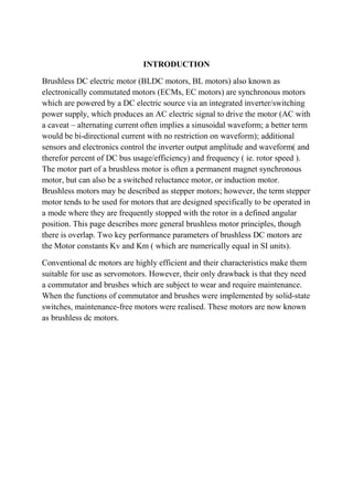
  • 20. A typical controller contains 3 bi-directional outputs (i.e. frequency controlled three phase output), which are controlled by a logic circuit. Simple controllers employ comparators to determine when the output phase should be advanced, while more advanced controllers employ a microcontroller to manage acceleration, control speed and fine-tune efficiency. Controllers that sense rotor position based on back-EMF have extra challenges in initiating motion because no back-EMF is produced when the rotor is stationary. This is usually accomplished by beginning rotation from an arbitrary phase, and then skipping to the correct phase if it is found to be wrong. This can cause the motor to run briefly backwards, adding even more complexity to the startup sequence. Other sensorless controllers are capable of measuring winding saturation caused by the position of the magnets to infer the rotor position. TERMINAL CHARACTERISTICS In DC MOTORS of 0.1 hp(74.60 watts) or less a permanent magnet is most useful comparing motors below 1.25 inch in diameter,permanent magnet motors runs cooler than wound field types because no power is expanded to maintain a magnetic field. The permanent magnet field functions perfectly for thousands for hours of operation and losts indefinetly on the shelf.Permanent magnet motorsa re easily reversed by changing the polarity of the voltage applied to the connecting terminals.They are capable of high-stall torque and function perfectly in long duty cycle applications. Dynamic breaking is easily obtained by marcly applying a short circuit to the motor terminals after voltage is removed. Figure 1 illustrates a speed-torque current-torque curve for a permanent magnet motor.Each curve is a theoretical straight line since the permanent magnet and armature winding are constant in a given motor.Current varies in proportional to torque and the slope of this curve is a torque constant „K‟.
  • 21. Figure 2 shows that with the permanent magnet motor no load speed varies inversely with field strength and stall torque varies directly with field strength.In this illustration curve “a” is the lowest value,curve “b” is the economical and curve “c” is the maximum value of field strength Figure 3 indicates the result of changing the applied voltage to a permanent magnet motor.No load speed changes proportionally to voltage,resulting in a family of parallel speed-torque curves.Remember that voltage determines speed,and only torque will determine current.
  • 22.
  • 23. Speed Controller Circuit: The robot I intend to build will be a 4WD bot with a skid steer system so to do this best I have opted to build 2 a controller system moulded around a 4QD DCI111. (A DCI111 converts radio signals into useable signals) Because of this the inputs on my controllers have to be similar to the 4QD units. The next things to consider are the motors that I will be using. Bosch 750‟s seem to be quite popular (so are ford escorts and they are crap) so I will just go ahed and use the many starter motors that I have lying around. This results in DC Motor Control & Interfacing Circuit: A permanent magnet DC motor responds to both voltage and current. The steady state voltage across a motor determines the motor‟s running speed, and the . current through its armature windings determines the torque. Apply a voltage and the motor will start running in one direction; reverse the polarity and the direction will be reversed. If you apply a load to the motor shaft, it will draw more current, if the power supply does not able to provide enough current, the voltage will drop and the speed of the motor will be reduced. However, if the power supply can maintain voltage while supplying the current, the motor will
  • 24. run at the same speed. In general, you can control the speed by applying the appropriate voltage, while torque is controlled by current. In most cases, DC motors are powered up by using fixed DC power supply, therefore; it is more efficient to use a chopping circuit. Back EMF PM Motor Speed Control Circuit: A 12 V control supply and a TRW BL11, 30 V motor are used; with minor changes other motor and control voltages can be accommodated. For example, a single 24 V rail could supply both control and motor voltages. Motor and control voltages are kept separate here because CMOS logic is used to start, stop, reverse and oscillate the motor with a variable delay between motor reversals. Bidirectional DC Motor Speed Controller This kit allows controlling the speed of a DC motor in both the forward and reverse direction. The range of control is from fully OFF to fully ON in both
  • 25. directions.This kit overcomes both these problems. The direction and speed is controlled using a single potentiometer. Turning the pot in one direction causes the motor to start spinning.turning the pot in the other direction causes the motor tospin in the opposite direction. The center position on thepot is OFF, forcing the motor to slow and stop before changing direction. PWM DC Motor Speed Control: The left half of the 556 dual timer IC is used as a fixed frequency square wave oscillator. The oscillator signal is fed into the right half of the 556 which is configured as a variable pulse width one-shot monostable multivibrator (pulse stretcher).
  • 26. DC Motor Controlled with PWM Resources: Here is a description of the driver circuit. It's based on the Microchip AN531 Application Note titled "Remote Positionner". The circuit given in the application Note do not work , so this is a correction of the circuit: DC MOTOR CONTROL USING A SINGLE SWITCH This simple circuit lets you run a DC motor in clockwise or anti-clockwise direction and stop it using a single switch. It provides a constant voltage for proper operation of the motor. The glowing of LED1 through LED3 indicates that the motor is in stop, forward rotation and reverse conditions, respectively.
  • 27. Bidirectional DC motor speed control using Pulse Width Modulation: The simplest method of implementing microcontroller controlled H-bridge drive of a reversible DC motor is to buy one of many commercial H-bridge IC's availible on the market. These can be purchased separately as an H-Bridge with a separate H-Bridge controller IC, or as an all-in-one IC. Unfortunately, there are several hurdles that sometimes frustrate this approach. Students often find these devices hard to find, as they are apparently in high demand. Secondly, many of these devices have limited current drive ability, such that larger DC motors end up running sluggish or stalling easily. One option is to build your own H-bridge from discrete parts, as shown below. Low-Cost DC Motor Speed Control with CMOS ICs: Two low-cost CMOS ICs manage a 12 VDC, current-limited speed control circuit for DC brush motors. The circuit design uses PWM (pulse width modulation) to chop the effectiveinput voltage to the motor. Use of CMOS
  • 28. devices gives the benefits of low power, minimal heat and improved longevity. The overall design is simple, inexpensive and reliable, and is useful in applications such as embedded DC motor control where efficiency, economy and performance are essential. Digital Speed Control by Anthony Psaila: My design is based around three parts: The controller board. This is a fully digital circuit that takes the 1ms to 2ms pulse from the receiver and converts it into a pwm train at 1Khz. It uses six cmos ics (74hc and 40 series) and a 4Mhz crystal clock. The only other components are one resistor and two capacitors to complete the crystal clock and a capacitor across the supply for smoothing. This was built on a printed board measuring 2 x 2.25 inches using standard components (on the boat there was no shortage of space). If surface mounted devices are used, the lot can be crammed into a much smaller space. The circuit can give a resolution of 128 steps (7bits). Some day I will expand it to have reverse function, but this is better done by a switcher circuit supplied from another channel (my reciever can give 7 channels and I am using only two at present).
  • 29. What is a Brushless Driver/Controller? A Brushless Driver and/or Controller is a device that is used to run/control a Brushless Motor. They are also known as Speed Controllers and often referred to as Electronic Speed Control or ESC. Their main purpose is to “drive” the motor, in other words make it run. There are many different types that are manufactured for different applications. The main purpose of a Controller/Driver is to drive a motor at a speed where a signal is taken that represents that demanded speed. If the speed of the motor is measured, then it is a Feedback speed controller or also known as a closed loop speed controller. If the speed isn't measured then it is called an open loop speed controller. A feedback speed controller is more complicated than one that is not, but is much better and more efficient. Motors come in a variety of forms, and the speed controllers/drivers motor driver output will be different dependent on these forms. How does a Brushless Driver and Controller work? Theory of a DC motor speed controller/driver
  • 30. The speed of a DC motor is directly proportional to the supply voltage, so when the supply voltage is reduced, so is the speed, and vice versa. An example is, if your supply voltage is 12 volts and you decrease to 6 volts, then the speed will now run 50% slower than at 12 volts. Now, the question is, how can that be achieved when you have a battery or supply fixed at 12 volts? The speed controller works by varying the average voltage sent to the motor. It could do this by adjusting the voltage sent to the motor, but this is inefficient to do. A much more efficient way to do this is, to switch the motors supply on and off very quickly. When the switching is fast enough the motor will only recognize the average effect. It will not notice that it is actually being switched on and off. The average speed of the motor increases, as the amount of time that the voltage is on increases compared with the amount of time that it is off. This on-off switching is performed by what is called a power MOSFET (Metal-Oxide- Semiconductor Field Effect Transistor). MOSFETs are devices that can turn very large currents on and off under the control of a low signal level voltage. The time it takes a motor to slow down and speed up depends on the inertia of the rotor, how much torque and friction there is. History of Brushless Drivers and Controllers: This takes us back to the 19th century. An electrical engineer and inventor by the name of Harry Ward Leonard introduced the Ward Leonard motor control system in 1891 and was the most widely used type of electric speed control. In a Ward Leonard system, a DC (direct current) generator is driven by a prime mover at a constant speed. The armature of a DC motor is connected directly to the armature of the DC generator. The DC motor drives the load equipment at an adjustable speed. By adjusting the output voltage of the generator, the motor speed is also adjusted, using a rheostat to adjust the excitation current in the field winding. The motor field is sometimes reduced to increase the speed above the base speed, but the motor field current is usually not adjusted. An AC (alternating current) motor is usually the prime mover, but a DC engine or motor can be used instead in order to provide the DC field excitation power supply. This system usually included an exciter generator that is driven by the prime mover. From the 1920s-1980s most electrically driven elevators used the Ward Leonard control system. This control system has been used up until the early 21st century. Different variations were implemented into the Ward Leonard system, but were still called by the same name generally. Electrical and mechanical types of adjustable speed drives and other new types developed after
  • 31. the Ward Leonard system was introduced. Electron tube types of DC motor controls began to develop in the 1920s, but electronic controls didn‟t begin to displace the Ward Leonard system until thyristor controlled drives were developed in the late 1960s. Ward Leonard drives were rapidly becoming obsolete by the mid 1970s, but replacements of existing Ward Leonard drives has continued until the beginning of the 21st century. Basic types of a Brushless Driver and Controller There are three different ways that Driver/Controllers are operated: • Manual • Remote • Automatic There are also different types of Driver/controllers: • Motor starters • Reduced voltage starters • Adjustable-speed drivers • Intelligent controllers Anaheim Automation also offers an Integrated Motor and Brushless Driver and Controller. This eliminates installation errors and creates a compact, easy-to-use package. Where is a Brushless Driver and Controller used? Brushless Drivers and Controllers are used practically everywhere and anywhere you can find a Brushless motor. Some of the industries they appear in, but not limited to, are: • Instrumentation • Medical • Appliances • Consumer
  • 32. Automotive • Industrial Automation Equipment • Aerospace • Military What Applications are Brushless Driver and Controller used for? Some applications brushless driver/controllers are used in are, but not limited to: • Appliances ο Wheel encoders ο Ice tray and dust box position sensing ο Door and lid open/close detection ο Low water indicator ο Motor current monitoring and AC input current detection • Automotive (High temperature and in cabin) ο Lighting ο Wiper systems ο Airbag deployment systems ο Brake systems ο Displays and infotainment ο Seat belt systems ο Closure systems • LED lighting and Displays ο Billboards ο Backlighting (cameras, mobile phones, laptop pc‟s,etc.) ο Illumination and signals
  • 33. Office Automation ο Printers ο Fax machines ο shredder • Portable ο Digital Camera ο Mobile Phone How to select a Brushless Driver and Controller? When selecting a driver/Controller for your motor, many things should be considered. What is your application? You will need to get specifics about the motor and the driver/controller and compare them to see if they are compatible. Once you have figured all this out, you can then begin to compare driver/controllers from different manufacturers. Advantages for Brushless Driver and Controller There are many advantages with Brushless. Such as the following, but not limited to: 1. Long lifetime 2. Efficient 3. Customizable 4. Different performance options on one driver/controller Disadvantages for Brushless Driver and Controller There are far more advantages than disadvantages for a Brushless driver/controller, but there are a few listed below: 1. High cost 2. Complex circuitry 3. An additional unit to a motor (takes up more space)
  • 34. Troubleshooting Brushless Driver and Controller When you are having problems with your Brushless Driver/ controller there are multiple things to look for. Different units will have their own way of indicating a problem of fault within the driver/controller. Most driver/controllers will have a fault light to help indicate a problem that has occurred. Some may have an “alarm” or noise of some sort. Some problems that may occur, but are not limited to are: 1. Blown phase 2. Improper parts within unit 3. Blown parts within unit 4. Improper wiring/installation (Check user guides for specific hook-up diagrams) There is always the possibility that something maybe shorted internally on the board. This is something you might not be able to fix by yourself. Most companies will have a warranty for the product which will allow you to send it back and get it properly fixed and tested. Physical Properties of a Brushless Driver and Controller Brushless driver/controllers come in all types of different shapes and sizes. They can be custom made and ordered from different manufacturers. Although there isn‟t a certain shape it, most driver/controllers have a rectangular or square shape to them. They can also come in very small packages as well as very big packages. Brushless Motor Driver/Controllers consist of, but are not limited to: ◊ PCB (Printed Circuit Board)
  • 35. Transistors ◊ Capacitors ◊ Resistors ◊ IC, Chips, microchips ◊ Diodes ◊ Potentiometers ◊ Terminal Blocks/ screw terminals ◊ Heat Sinks ◊ LEDs ◊ LCDs Formulas for a Brushless Driver and Controller ◊ AC to DC AC (1.414) – 2.8 = DC ◊ Output Power = (Torque)(No Load Speed) 1351.2 ◊ Rated Current = Torque (Torque Constant) ◊ Back EMF Ke = V kRPM ◊ Setting the Current Limit:
  • 36. The Current of the motor is monitored by the sense resistor. You can monitor this by using an oscilloscope. You will need to calculate the voltage (in milivolts) to set your cursor on your scope. Required Maintenance for a Brushless Driver/Controller Occasionally things go wrong with electronics. You should always make sure the environment of your Driver/Controller is within specifications of the unit so that everything will run smoothly and consistently. The temperature, air, dust, and pressure play a big part in electronics. You always want to make sure those allow your unit to run and operate properly at all times. Those factors are almost always unpredictable and change all the time.