Helical rotor pumps - benefits and limitations
•
0 likes•3,751 views

The document discusses helical rotor pumps, also known as progressive cavity, 'wiggle', or 'Mono' pumps. It describes the key benefits as being hygienic because all internal surfaces are smooth, non-shearing so they don't damage products, and able to pump a wide range of liquids and slurries. However, it also lists limitations such as the need for tight clearances between the rotor and stator, keeping rotational speed low to minimize friction, and potential damage if foreign materials get caught between the rotor and stator.

Recommended
More Related Content
Similar to Helical rotor pumps - benefits and limitations
Similar to Helical rotor pumps - benefits and limitations (20)
More from Business Industrial Network
More from Business Industrial Network (20)
Recently uploaded
Recently uploaded (20)
Helical rotor pumps - benefits and limitations
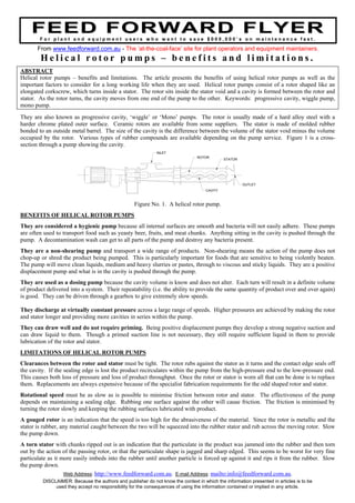
- 1. FFEEEEDD FFOORRWWAARRDD FFLLYYEERRF o r p l a n t a n d e q u i p m e n t u s e r s w h o w a n t t o s a v e $ 0 0 0 , 0 0 0 ’ s o n m a i n t e n a n c e f a s t . From www.feedforward.com.au - The ‘at-the-coal-face’ site for plant operators and equipment maintainers. H e l i c a l r o t o r p u m p s – b e n e f i t s a n d l i m i t a t i o n s . ABSTRACT Helical rotor pumps – benefits and limitations. The article presents the benefits of using helical rotor pumps as well as the important factors to consider for a long working life when they are used. Helical rotor pumps consist of a rotor shaped like an elongated corkscrew, which turns inside a stator. The rotor sits inside the stator void and a cavity is formed between the rotor and stator. As the rotor turns, the cavity moves from one end of the pump to the other. Keywords: progressive cavity, wiggle pump, mono pump. They are also known as progressive cavity, ‘wiggle’ or ‘Mono’ pumps. The rotor is usually made of a hard alloy steel with a harder chrome plated outer surface. Ceramic rotors are available from some suppliers. The stator is made of molded rubber bonded to an outside metal barrel. The size of the cavity is the difference between the volume of the stator void minus the volume occupied by the rotor. Various types of rubber compounds are available depending on the pump service. Figure 1 is a cross- section through a pump showing the cavity. Figure No. 1. A helical rotor pump. BENEFITS OF HELICAL ROTOR PUMPS They are considered a hygienic pump because all internal surfaces are smooth and bacteria will not easily adhere. These pumps are often used to transport food such as yeasty beer, fruits, and meat chunks. Anything sitting in the cavity is pushed through the pump. A decontamination wash can get to all parts of the pump and destroy any bacteria present. They are a non-shearing pump and transport a wide range of products. Non-shearing means the action of the pump does not chop-up or shred the product being pumped. This is particularly important for foods that are sensitive to being violently beaten. The pump will move clean liquids, medium and heavy slurries or pastes, through to viscous and sticky liquids. They are a positive displacement pump and what is in the cavity is pushed through the pump. They are used as a dosing pump because the cavity volume is know and does not alter. Each turn will result in a definite volume of product delivered into a system. Their repeatability (i.e. the ability to provide the same quantity of product over and over again) is good. They can be driven through a gearbox to give extremely slow speeds. They discharge at virtually constant pressure across a large range of speeds. Higher pressures are achieved by making the rotor and stator longer and providing more cavities in series within the pump. They can draw well and do not require priming. Being positive displacement pumps they develop a strong negative suction and can draw liquid to them. Though a primed suction line is not necessary, they still require sufficient liquid in them to provide lubrication of the rotor and stator. LIMITATIONS OF HELICAL ROTOR PUMPS Clearances between the rotor and stator must be tight. The rotor rubs against the stator as it turns and the contact edge seals off the cavity. If the sealing edge is lost the product recirculates within the pump from the high-pressure end to the low-pressure end. This causes both loss of pressure and loss of product throughput. Once the rotor or stator is worn all that can be done is to replace them. Replacements are always expensive because of the specialist fabrication requirements for the odd shaped rotor and stator. Rotational speed must be as slow as is possible to minimise friction between rotor and stator. The effectiveness of the pump depends on maintaining a sealing edge. Rubbing one surface against the other will cause friction. The friction is minimised by turning the rotor slowly and keeping the rubbing surfaces lubricated with product. A gouged rotor is an indication that the speed is too high for the abrasiveness of the material. Since the rotor is metallic and the stator is rubber, any material caught between the two will be squeezed into the rubber stator and rub across the moving rotor. Slow the pump down. A torn stator with chunks ripped out is an indication that the particulate in the product was jammed into the rubber and then torn out by the action of the passing rotor, or that the particulate shape is jagged and sharp edged. This seems to be worst for very fine particulate as it more easily imbeds into the rubber until another particle is forced up against it and rips it from the rubber. Slow the pump down. CAVITY ROTOR STATOR INLET OUTLET Web Address: http://www.feedforward.com.au. E-mail Address: mailto:info@feedforward.com.au. DISCLAIMER: Because the authors and publisher do not know the context in which the information presented in articles is to be used they accept no responsibility for the consequences of using the information contained or implied in any article.
- 2. Stator material selection is confined to a variety of different rubbers. The product being pumped dictates whether hard or soft rubber is used. It maybe necessary to try different rubber until the most long-lived is found. Fit a pressure relief valve on the discharge of the pump. They are a positive displacement pump and must not be deadheaded. The relief valve can relieve back into the supply tank or back to the suction pipe work to the pump. Don’t dry run the pump. The rubbing action of rotor over stator requires lubrication. If run dry chunks of rubber will be ripped out of the stator. To protect the pump, create a dead-leg using the inlet and outlet piping. Liquid sits in the dead leg and keeps the pump flooded. Another way is to run a recirculation pipeline from the discharge pipe back to the inlet pipe. The recirculation pipe is of small bore so the majority of the flow still discharges through the outlet pipe. A recirculation line or dead leg will not work for thick slurries, or liquids that set when cold. In this case it may be necessary to purposely introduce a clean lubricating fluid. There are temperature limits for the rubber in the stator. Depending on the rubber, its working temperature limit before becoming too soft is between 90o C and 150o C. Pump speeds depend on the cleanliness and lubricating properties of the liquid being pumped. With clean, cool, lubricating liquids, speeds can be faster, however as soon as particulate is present in the product, or the liquid viscosity is high, they need to be speed reduced through a gearbox or belt and pulley drive. Shaft sealing requires a mechanical seal or a packed gland. If the product is viscous or a slurry, the seal will need a clean liquid flush to prevent product coming back up the shaft of a packed gland pump or across the faces of a mechanical seal. Mike Sondalini – Maintenance Engineer. Postal Address: FEED FORWARD PUBLICATIONS, PO Box 578, BENTLEY, West Australia, 6102. E-mail Address: feedforward@bigpond.com Because the authors and publisher do not know the context in which the information presented in the flyer is to be used they accept no responsibility for the consequences of using the information contained or implied in any articles.