SlideShare a Scribd company logo
1 of 20
Download to read offline
1
TUBULAR STRUCTURES IN ARCHITECTURE
MICK EEKHOUT
Octatube, Rotterdamseweg 200, Delft, The Netherlands, and
Product Development, Delft University of Technology, Delft, The Netherlands
E-mail: m.eekhout@octatube.nl; a.c.j.m.eekhout@tudelft.nl
For structural engineers, tubular structures are most interesting for buildings with larger spans.
For architects, other tendencies in the design of tubular structures of buildings are valid which
have an influence on a much smaller scale, more intense, often more complex than just large
spans. From the 1970s onwards, high-tech architecture has caught much attention. After 1995,
accelerated by the intense use of the computer, attention came also on deviating geometrical
forms of buildings, “fluent-form” buildings and “free-form” buildings. Fluent forms of buildings
have geometries which can be derived by mathematical formulas and hence are more or less
communicable. Free forms are free forms and literally cannot be generated by mathematical
forms. The form of these buildings has to be established by the architect, and other parties just
have to follow. Yet the future of tubular structures is only colored by these pilot projects. The
majority of applications is still quite functional and straightforward.
Keywords: Architecture, tubular structures, free forms, high-tech.
1 Introduction
For half a century, tubular structures have been popular in architecture. Originally they were
seen as substitutes for classical open steel profiles, but the circular and square cross sections had
better advantages over open profiles. Tubes were developed gradually and finally exploited to
achieve results that were never dreamt of with conventional steel structures. Material efficiency
of the cross section led to open profiles which were extremely good for bending. Tubes are
better in compression, but tubes also have an esthetic appearance which lifts them above open
profiles. They are not angular, but more fluent. In general, they give a smoother appearance in
contrast with the more-robust open profiles. Tubular connections can be designed to be abrupt,
in the case of many tubes connecting at one point (Fig. 1), or to be smooth, whereby forces
“visually flow” from one tube into other tubes (Fig. 2).
Figure 1. Abrupt connection of tubes Figure 2. Smooth connection of tubes
Eekhout, M.
2
The development of tubular structures, in particular for large spans, has been guided by
structural engineers not only by their pure function as load-bearing structures, but has also been
increasingly influenced by architectural engineers with more design considerations involved.
2 Product development of tubular structures
The time of standard products seems to be over. In the trio of standard products, system products
and special products in product development, system products like space frame structures are
almost past. Architects want to design their own structures, with a remarkable project
characteristic. From the experience with system products we know the base of system products
are half-products like steel tubes and pipes, which get a free form production treatment, often
maltreatment: cornering, bending and curving, all to transform simple straightforward steel tubes
into ingenious tubular components, each with their own form and connections, but at a cost. We
can apparently afford this as we are living in quite a luxurious world.
Despite this reasoning in general, in the last decade regular geometric structures were the
favourite and still make up the vast majority of buildings nowadays. It is the rational structural
design towards minimal material use, combined with repetition in production and assembly, that
makes economic structures. Frei Otto was the pioneer of minimal structures, leading to his
membrane and cable net structures of the 60s and 70s (Fig. 3) with complete separation of
tensile forces (in membranes and cables) and compression forces (in masts and foundations).
Figure 3. Olympic Stadium Munich, Frei Otto, Günther Behnish
Extreme separation of forces leads to heavy foundation anchorings, out of sight, which do not
directly follow the laws of minimal material use because of larger bending moments than usual.
In effect, the use of minimal material has been lost ever since the “Bird’s Nest” of Beijing,
China (2008), Fig. 4, which consumed eight times the amount of steel compared to a regular
stadium of the same size.
Figure 4. National Stadium ‘Bird’s nest’ Beijing, Herzog & De Meuron
17th
International Symposium on Tubular Structures (ISTS17)
3
However, economic structures do not make a winner at competitions when the jury knows that
many more geometries are possible. Architects get bored by predictable regular geometries.
They want to design and not just obey the laws of regularity in geometry. They want to win a
design competition by astonishing the jury or the client. The omnipotent abilities of computer
rendering, and later structural analysis by computer, make tubular structures very suitable for
structural manipulations. Irregularity, because of architectonic reasons, became more
experimental for architects in order to win design competitions with designs that amaze the jury,
and later the world. Designs of new stadiums (e.g. Fig. 5) prove this.
Figure 5. Design Competition for 2020 Olympics: National Stadium Tokyo, Zaha Hadid
3 High-tech structures
In 1997 the CIDECT/TU Delft book “Tubular Structures in Architecture” was published in five
languages and 25,000 copies were sold worldwide. In between the distinguished company of
structural engineer and architect, the engineering architect or architectural engineer always has a
different view. This resulted in the book “Tubular Structures in Architecture” which explained
the possibilities, reasoning and realized examples of high-tech Architecture. Actually, high-tech
architecture was introduced to the world with the Beaubourg Centre (Fig. 6) as an explosion “to
change fashion in architecture” as the late Ted Happold, the collaborating engineer of Renzo
Piano on the project, said at the LSA Conference in Sydney, in 1986.
Figure 6. Centre Pompidou, Paris, Piano & Rogers
Eekhout, M.
4
High-tech architecture became popular in the world after the Pompidou Centre in 1978. As it
was, it turned the normal straightforward reasoning of structural engineers upside down. Why
design an obvious and simple structure, when you can also design an astonishing, or even an
exciting, structure? Nowadays, more than 20 years after the first issue of the book, a generation
later, one could say that the book was written in the middle of the high-tech era. The structure of
a building, as a load-bearing mechanism, had always been important in the design of buildings,
but was never of much concern for architects. However, showing them the structural skeleton
made structural design exciting for a whole generation of architects. Designing according to the
bending moment distribution in a structure had its own appeal for architects. It made structures
even more understandable and prominent for the observer, and for the user of buildings. In many
structural high-tech designs the separation of tensile forces and compression forces plays a
visual role, sometimes even exaggerated as a show-off.
The book was written, however, on realised hand-designed structures, with hand-engineered
details and shop drawings. Sometimes it was a wonder that, without exacting surveying
apparatus, these prefabricated structures fitted in reality to the millimeter. The eleven roof
segments of the 50 m space frame for the Aquadome in Bremen (Figure 7) were installed, but
would the closing segment number 12 fit? It actually did, the open space for segment number 12
was 3 mm too wide, which was easy to be filled. It was exciting like a rocket launch!
Figure 7. Aquadrome Bremen, Hamming
High-tech structures often were products of a deliberate collaboration between the architect and
the structural designers in one project, a collaboration more intense than before. Architects
understood high-tech structures. Kanzai Airport (Fig. 8) designed by architect Renzo Piano and
structural engineer Peter Rice marked a moment in time in a cross-over towards complex
geometry design. The design followed a complicated geometrical form with a large radius for
the roof form. Producers who had underestimated the complexity of these tubular design
structures could easily suffer gigantic losses on these early free-form architectural projects.
Figure 8. Kanzai Airport, Osaka, Renzo Piano
17th
International Symposium on Tubular Structures (ISTS17)
5
4 Sculptural designs and free-form structures
Only 15 years later, in 2011, the second and extended edition of “Tubular Structures in
Architecture” was written and published. Drawing tables had already been removed from
architects’ offices. The influence of the computer in architectural offices was amazing. The
computer was seen initially as a substitute for boring or complicated hand-made designing and
engineering. From the mid-1990s the use of computer programs in the architect’s office gave
unexpected and exciting results. After confirmation of the flawless geometrical computation
capacity of computer programs, more complicated designs enabled more complex geometries to
be realised. The introduction of the computer evoked more complex designs (e.g. Fig. 9) in
tubular structures than were ever-possible to be realised.
Figure 9. A complex tubular structure; Guillemins, Luik, Santiago Calatrava
4.1 The Guggenheim museum in Bilbao was the start of free-form architecture
The transition in architectural geometry was dramatically pointed in history by the Guggenheim
Museum, designed by Frank Gehry, and realised in 1997 (Fig. 10). It was the flagship of free-
form architecture. I remember the first time I saw it, when giving a lecture in Bilbao on the issue
of “Tubular Structures in Architecture; I had to adapt my carousel slides. The museum had come
like a satellite from outer space, landed in Bilbao and changed the outlook of the entire city. A
building under construction for a shopping centre, a bit further down the river, all of a sudden
looked helplessly old-fashioned, almost 1960s. So just one building changed the outlook and the
future of an entire city. A former industrial harbor city all of a sudden became the world place to
be for tourists. Bilbao is Guggenheim and Guggenheim is Bilbao.
Figure 10. The new appearance of the Guggenheim Museum, Bilbao, Frank Gehry
Eekhout, M.
6
But the technology employed for this building was outdated. Photographs of the construction
work were hardly published. Open profiles had large connection plates and all members were
welded on the site, so that they would fit (Fig. 11). It was building a new design with old-
fashioned ingredients. Maybe Gehry had been shocked by the performance on site, because in
his next project he became more fierce with his explicit design engineering.
Figure 11. Load-bearing structure of Guggenheim Bilbao during construction phase
4.2 Risky design developments as moonshots
Bold architects even went so far as to even design free-form structures that were impossible to
be built, before computerisation of the architectural designs (Fig. 12). Free-form structures
cannot be generated by mathematical formulas. But too-early adopting and too-eager architects
saw mishappenings. Designs by architects without knowledge of adapted execution in
production and on site either caused projects to be cancelled, architects put on the blacklist of
clients, unfortunate production parties to go bankrupt, and the near-bankruptcy of Europe’s most
famous curtain wall company, Gartner (taken over by Permasteelisa).
Figure 12. Structural proposal for Wilhelmina Pier, Zwarts & Jansma
We say now: these architects were light years ahead of their time. Sometimes they were much
too early and under-estimated the capacities of the production industry to execute their designs,
without any prior knowledge gained from previous projects, as there were no prior projects.
17th
International Symposium on Tubular Structures (ISTS17)
7
Figure 13. Deutsche Genossenschaft Bank Berlin, Frank Gehry
For production companies these “moonshots” (e.g. Fig. 14), which are very complicated projects
with an aim, but without appropriate knowledge and no prior experience, can be fatal and can
lead to bankruptcy. Usually producers say: the architect is praised and the churchyard is full of
“naïve losers” and other disillusioned contractors. So, free-form architecture and the shortage of
experience and proper production efficiencies also led to a number of economic failures.
Figure 14. Rabin Center, Tel Aviv, a personal “moonshot” project, Moshe Safdie.
Gradually, after a number of abortive projects, then a number of barely successful projects, and
after publications on the required and more-or-less (economically) successful free-form
technology, more projects were realised. As always, design-eager architects and wealthy clients
were praised. It led to understanding and further development of the required free-form
technology. The road to success is paved with many “moonshot” gravestones of producers.
After many free-form structures, one could notice that the adage of light-weight structural
design, as in the “minimal material” era of Frei Otto, was forgotten and was been exchanged by
heavy and moment-resistant structures (see the form-driven of free-form designs of Frank
Gehry, Fig. 15).
Eekhout, M.
8
Figure 15. Louis Vuitton Museum Paris, Frank Gehry
4.3 Prototyping to get acquainted with new technologies
An alternative for the initial absence of appropriate knowledge in this upcoming new field of
expertise was to make use of material prototypes, to be built during the design process or
engineering process. Prototypes (Figs. 16 and 17) designed and engineered by the architect and
structural engineer would reveal to the offices many uncertainties and secrets that cannot be seen
from computer models, not even the most advanced types. Small details are worthwhile being
made in real materials, manipulated in the hands of the designers to get accustomed to the real
material, real sizes and the weight of material details. There are always material flaws. Large-
scale prototypes cost extra money, of course. Dutch clients do not want at all to invest in such
prototypes, as they see it as superfluous energy and investment. In America and in Asia,
however, we have experienced that making prototypes is often a more-common practice.
17th
International Symposium on Tubular Structures (ISTS17)
9
Figure 16. Prototype of AFAS Dome at Octatube Figure 17. Testing of mock-up in Tokyo
From prototypes, not only can one party learn but all involved as partners in a design team can
gain. Also, if performed before a tender is issued, all tendering parties could draw upon their
lesson which prevents “wild-west tendering”. In many projects the client can prevent losing
much money, as such prototyping is seen as enabling efficiencies for the entire process.
Figure 18. Tubular space frame in the roof of Raffles City, Singapore
In other cases, internal rivalries within a building design development and engineering team
could be settled more easily when everyone’s mutual experience was visual. Also, prototypes
could help to prevent a loss of time. Buildings with complex geometries benefit from
prototyping, as “nothing is normal”.
Eekhout, M.
10
Figure 19. Octatube’s alternative design of the Deutsche Genossenschaft Bank Berlin, Frank Gehry
4.3 Frontrunners
Architects who were working enthusiastically at the forefront of new development of free-form
design were only retarded by the production and construction industry, who had no idea how to
make free-form constructions with elements and components that deviated from simple tubes
and nodes. Architects and engineers did not collaborate with producers to develop free-form
production technology. They expected that throwing an invitation for tender “over the wall”
would automatically generate success. Well, at first it harvested impossible prices and generated
much misunderstanding.
Figure 20. Elevation of the 45 x 75 m-large Mediatheque’s roof structure by Octatube, Zaha Hadid
They said: “The industry could not cope”, et cetera. Dreaming on computer-aided manipulative
geometries went far beyond the imagination and the usual, experienced capacity of the
producing parties. They could not diminish the many risks involved.
4.3 Self-overestimation or “moonshot” thinking?
In 1962, President John F. Kennedy gave a speech: “We choose to go to the moon in this
decade”, and that was the beginning of the ambition of an entire nation to reach the moon. We
could say that JFK did not set that goal by knowing how we could achieve it, or by promising
that it would be easy; he simply said that we were going to accomplish something incredible,
setting the timeframe and inspiration towards action. The money would come later.
In the case of the Rabin project (Fig. 14) my company Octatube and I had to overcome a
“moonshot” with as much as eight innovations packed into one project (Fig. 21):
17th
International Symposium on Tubular Structures (ISTS17)
11
 Glass-fibre-reinforced polyester;
 Free-form architecture;
 New computer programing;
 All elements and components integrated into a big BIM model;
 Large smooth surfaces required;
 Innovative production out of our sight, in a specialist factory;
 Hostile attitude from the Israeli approving officials;
 Assembly out of sight, 5000 km from the office.
Figure 21. “Moonshot”-project Rabin Centre; eight innovations in one project
This obviously led to an almost-unmanageable, technically innovative project. “Moonshot
thinking” is derived from NASA working with limitless governmental budgets, unlike the
discrete budgets in projects or companies which are restricted, as are a company’s limits.
With only a few projects per year in any country, the eagerness amongst producers to adapt their
production capacities in their own companies was not overwhelming. However, for large pilot
projects, and especially prominent projects, money was available to adapt production technology
by introducing computer-aided manufacturing, by introducing associated assembly methods with
a main focus on geometric surveying.
Architects like Frank Gehry had obviously learned from the Guggenheim and dictated, in this
millennium, their own specifications for the design of free-form components. Gehry specifically
requests his buildings to be built as he has designed and engineered, with no alternatives
possible (Fig. 15).
4.4 Producers or specialist contractors?
Some manufacturers developed their own “vocabulary” in order to have a technical answer to
free-form architectural designs. Usually these designs are quite large and, within the
development of a project, there is space and money available to develop new production
vocabulary for each new free-form project. With many experiences in the Octatube office, as
illustrated in this publication, the technical engineering of a free-form architectural design often
follows a particular project characteristic.
Eekhout, M.
12
Figure 22. Design Proposal for Capital C, Diamond Beurs Amsterdam
Figure 23. Construction photograph of Rokin cylindrical roof, Amsterdam, Rijnboutt
All architectural designs are different. The architect wants to achieve the “first-on-the-block
effect”: a first-car lover wants a pink Cadillac. The second buyer will never want a pink Cadillac
as he does not want to copy the forerunner. An architect never wants to be seen as an imitator or
an adaptor of another architect from a previous project, but always strives to be purely original.
This does not lead to systems engineering and production; it leads to “Industrialisation in units
of one”. Most of the experience from earlier designs cannot be directly or literally used in a next
project. What remains are the willingness to perform free-form technology, to exploit the
process experiences from earlier projects, and the free-form engineering attitude. The goal is to
have computer programs inter-relating between architectural design, component engineering,
production machining, and geometric surveying of components in their expected positions on
site; but attitude and experience come first.
My own professional part, as an architect in the world of structural designers and structural
engineers, led me to develop a new “vocabulary” for space frame structures with tubular
components, and later for glass structures, by undertaking many successive “design & build”
projects. Rather small projects were attempted at first, with clear or restricted risks, using an
incremental approach. “Step by step”, as Piano once wrote. As a design engineer, never throw an
impossible design over the fence and expect that it will work. Misinformation from the
17th
International Symposium on Tubular Structures (ISTS17)
13
designing parties, misunderstanding, misinterpretation and lack of motivation from the side of
producers, do not lead to successful answers by producers in the tender processes. When you, as
a design engineer, do not know how your design has to be made, don’t expect others to take up
that risk either.
5 Complex Tech-Architecture
 Tubular designs are visual designs that are pleasing to the eye;
 Tubular structures are easy to be manipulated in the design phase: bent or curved;
 The geometry of tubular steel structures is increasing in complexity due to design
manipulations with the aid of computer programs;
 Tubular structures become an integrated part of the building envelope;
 Complex detailing beyond the structural function is required around tubular structures.
Architects have a tendency to make “basic” tubular structures more complex by using exterior
and interior cladding and glazing, by mixing tubular steel structures with other structural
materials like glass, by adding more functions like sound absorption, and by designing project-
typical structures.
Perhaps the best drive in the continuous quest for disruptive innovations in tubular structures
results from curiosity, creativity, persistence, a bit of naivety, a positive spirit and belief in
ambitions, and, of course, the joy in making new things that last.
6 Examples of projects from regular to irregular geometry
6.1 Air Traffic Control Leader bridge, Schiphol Airport, NL
Eekhout, M.
14
Figure 24. Air Traffic Control Leader bridge, Ector Hoogstad
Air Traffic Control Leader bridge at Schiphol Airport, a pedestrian bridge of 50 m span
between two buildings at Schiphol Airport, Amsterdam, is made of square or circular hollow
sections (CHS) in a regular structural system. The original design showed a cigar-shaped form
with a wider cross section in the middle of the span and a smaller cross section at both
connecting ends. However, this cigar-form was substituted by a straight elliptical form for cost
reasons. It saved approximately 30% on the total budget of the tubular structure, sandwich
claddings and glazing panels together. Architect: Ector Hoogstad Architecten
6.2. AFAS Dome, Leusden, NL
Figure 25. AFAS Dome, Leusden, NL, Van der Velt & Just Architects
AFAS Dome, Leusden, NL, is a regular network dome made in CHS with welded connections,
highly sophisticated glass cladding, and internal cabling for lighting, computing and fixtures.
The dome is under construction at the time of writing. The model (fig. 16) shows that the
connections are made as rigid, bolted connections with four internal bolts. In the centre of the
CHS tubes there is enough space for electrical cables. Architect: Van der Velt / Just Architects.
6.3. Friesland Bank Dome, Leeuwarden, NL
Friesland Bank Dome, Leeuwarden, the Netherlands. A dome structure in a regular geometry,
but suspended from three arches, as the foundation only allows three foundation anchorage
points between existing buildings. The dome structure is also loaded by a large flat roof on one
side, at the side of the open atrium. Which makes it a heavily loaded, suspended dome.
Architect Aat van Tilburg, Rotterdam / Harmen Grunstra, Bolsward.
17th
International Symposium on Tubular Structures (ISTS17)
15
Figure 26. Friesland Bank Dome, Aat van Tilburg
6.4 Hudson Bay, Amsterdam, NL
Figure 27. Hudson Bay, Rijnboutt
Hudson Bay, Amsterdam, has a top floor restaurant, with a beautiful sight overlooking the centre
of Amsterdam. The form of the tubular structure takes a regular cylindrical shape made of
rectangular hollow sections (RHS) which have a slight twist incorporated in the connections to
amaze the world with a diagonal geometry instead of the usual orthogonal geometry. It gives the
indoor space a “swing”. Architect: Rijnboutt.
Eekhout, M.
16
6.5. The Southgate Canopy, Delft, NL
Figure 28. Southgate Canopy, Mick Eekhout
The Southgate canopy in Delft has been made in a waving system of CHS, specifically to show
the possibilities of cold-warping of laminated glass made with flat and orthogonal glass panels.
Architect: Mick Eekhout
6.6. London Business School, London, UK
Figure 29. London Business School, Sheppard Robson
London Business School, London, has two intermediate glazed spaces with specially made
triangular hollow sections in an irregular composition. The triangular hollow sections leave no
shadow at their lower side. They leave attention for the three existing Victorian buildings which
they connect. Architect: Sheppard Robson.
6.7. Glass House, Malmö, Sweden
The Glass House of Malmö has a smooth form made entirely of flat glass panels, supported by a
waving structure of CHS tubes in an elliptical form with a connecting rib at the top. Design:
Monica Gora and Ian Liddell / Happold, Engineering by Octatube.
17th
International Symposium on Tubular Structures (ISTS17)
17
Figure 30. Glass House, Malmö, Monica Gora
The design challenge was to engineer this principally fluid form, as in the plexiglass model, to
become a structure with preferably flat glass panels, not with hot-bent or cold-bent glass. The
solution was to make a series of arches almost perpendicular to the surface of the glass skin.
This skin became a polygonal surface, made of flat-glass panels. All corners are different, so the
“Quattro” nodes connecting the tubular structure with the glass panels were all individually
made in a different form. From the choice of single laminated glass or insulated glass panels,
both laminated, the client made her choice for single glass for maximum transparency.
Design: Monica Gora and Ian Liddell / Happold.
6.8. Van Gogh Museum Entrance Hall, Amsterdam, NL
Figure 31. Van Gogh Museum, Amsterdam, Hans van Heeswijk
Eekhout, M.
18
The Van Gogh Museum Entrance Hall in Amsterdam has only a basic structure consisting of
two free-formed CHS on seven CHS columns, with steel shoes to fit in the laminated glass fins
which were produced in China. The shoes thus had to be provided to a very high accuracy, of
only a few millimeters, which is seldom in free-form. The two tubes are 3D bent. Architect:
Hans van Heeswijk.
6.9. Diamond Exchange Building, Amsterdam, NL
Figure 32. Diamond Exchange Building, Amsterdam, Zwarts & Jansma
The Diamond Exchange Building in Amsterdam has been provided with a free-formed grid as a
topping-up shell roof made of RHS. The system was made in the form of a square single-layered
grid of which each member and each node was different because of the free-form geometry. The
shell has been made in the form of separate ladders, welded on an accurate mold, with singular
members in-between, bolted on site. Architect: Zwarts & Jansma.
6.10 Notre Dame, Paris, France
On April 15, 2019, the roof of the Notre Dame cathedral in Paris burned off completely,
including the central roof tower. The roof construction was entirely built of oak wood, more than
eight centuries old. All over Europe medieval churches have timber roof structures that
occasionally ignite after maintenance activities. Insufficient fire prevention measures can be
quite expensive in the long run. France will organize an international architectural competition,
in which the obvious discussion between tradition and amazing innovations will no doubt be
celebrated.
The technical solution, however, is simple. The plan of the cathedral is made of modules 7.5 x
15 m, with the central module in the crossing being 15 x 15 m. This makes it ideal for an old-
fashioned tubular space frame. The roof angle of 55º leads to a very regular space frame in a
cross form with 15 m-long tubular elements, which can be refined up to a module size of 7.5 x
7.5 m². The advantage is that a three-dimensional space fame has a large rigidity in both
directions of the plan and on all of its support points. Many of these support points, also being
the tops of the flying buttresses, have had a high thermal attack during the roof fire and can be
supposed to have been bent outwards. The nodal points of this space frame can bring the entity
of the tops of the load-bearing masonry construction to rest, either by fixing, or even by post-
bending backwards to relieve the extra compressions caused by the fire.
17th
International Symposium on Tubular Structures (ISTS17)
19
Figure 33. Possible roof structure with a standard space frame as an exactly fitting tubular roof
structure
The tower or “Fleche” from the time of Viollet le Duc around 1850 had a timber load-bearing
structure. It collapsed during the fire and punched through the cross vault, which is now open.
The other masonry vaults are still more-or-less in order. A new tower of a vertical design can be
imagined rising from the four diagonal-angle rafters, having fixed connections on the bottom
level and on the ridge of the space frame at its crossing. Many tower designs are possible,
straight upward or twisted. The space frame with member lengths of 15 m can also be
subdivided into lengths of 7.5 m, which will make the individual tubular members lighter. At the
vertical center of the space frame, on the horizontal cross members of the space frame, a
walkway can be realised at half-height of the roof volume. On the outside of the space frame
metal purlins will be connected with an interspace convenient for the cladding to be chosen.
The cladding can be made, as it has been for centuries, by lead panels on purlins, but this time
not with timber but steel purlins. Alternatively a roof cladding material like glass could be
chosen. However, in relation to the century-old lead material, glass materials age quicker. In
comparison with long-lasting lead panels, double-glass panels with a factory guarantee of only
10 or 20 years do not seem appropriate for a building that has to survive again the coming
centuries. It would, though, allow the possibility to have daylight enter into the central vault,
even if only small cladding surfaces were made of glass. The central cross vault has been
punched through by the collapsing central spire. This central vault could be reconstructed by
solid glass blocks, functioning as a brick vault, but now allowing daylight to enter into the
cathedral. The cathedral could get another daylight focus in the center of the cross-formed plan,
a completely new concept for a gothic cathedral. So tubular structures can contribute in a modest
way to the restoration of a famous cultural building.
Eekhout, M.
20
7. Conclusions for the Architectural Future of Tubular Structures
The architectural future of tubular structures is different from its structural and industrial use. In
the domain of structural engineers and tube producers, the vision of architects and designers,
illustrated by their proposals and realized projects, illustrates the state of the art of the
architecture of tubular structures. The multitude of tubular applications is quite straightforward.
However, architectural innovative design thinking leads the way forward qualitatively. The era
of high-tech structures, with their rather mechanically steered geometry, is apparently over. The
era of free-form structures has introduced complexity and complication in geometry. After two
decades of trial and error it has been split into fluent-form and free-form structures. Fluent form
has a communicable geometry because of the mathematics behind it, however complex that may
be. Free-form structures are really sculptural structures which are conceived by the designer as a
sculptor, without any mathematics behind them. Many of the complicated structures of Frank
Gehry are free-formed from random folded paper props, that are “frozen” from the moment they
leave the table of the handicraft master. They are measured and then put into a strictly obeying
geometry. It is no wonder that engineering, producing and realizing parties have to purchase the
same computer programs (i.e. Catia) that Gehry Associates use in their design, to assure that the
engineered geometry is exactly the designed one, which they can supervise. In following this
approach Gehry remains master of the game, all the way through to the opening of the building.
However, it is a demanding approach for the executing parties. Free-form geometries are
expensive to realize. In the case of the Rabin Center in Tel Aviv, architect Moshe Safdi gave a
“free-form” model, which had to be adjusted and refined. It was drawn in a 3D model which
could only be handled by one particular engineer. This project followed a similar route of
development as Gehry’s design and engineering development. Fluent-form designs (composed
from complex mathematical models), have less problems with communication. These forms can
be mathematically generated by different parties involved in the building team of a project. A
wise architect sells a competition-winning design as a free form design but generates it towards
realization as a fluent design. The more repetition, the more economic the structure will be.
Buildings with “industrialization in lots of one”, can be made, but at a cost.
In all, architects are very interested in the more sculptural architectural designs than just
straight-forward designs. Tubular structures have excellent characteristics to be handled as
sculptural structures, and to be pleasing to the eye.
Acknowledgments
It is a great honor to have been asked by Sub-commission XV-E of the International Institute of
Welding to present this “Kurobane Lecture” at the 17th International Symposium on Tubular
Structures, here in Singapore. Also, I would like to express my sincere thanks to Professor Jaap
Wardenier for being a very understanding structural engineering colleague and good friend.
References
Eekhout, M., Tubular Structures in Architecture, 2nd
Ed., ISBN 978-944-90675-01-1,
CIDECT, Geneva, 2011.

More Related Content

Similar to 2019 Kurobane Award - Lecture Mick Eekhout

Project report on multi storied building expertcivil
Project report on multi storied building expertcivilProject report on multi storied building expertcivil
Project report on multi storied building expertcivilMumairbuttg
 
Hi tech architecture
Hi tech architectureHi tech architecture
Hi tech architecturevats189
 
Hi tech ARCHITECTURE
Hi tech ARCHITECTUREHi tech ARCHITECTURE
Hi tech ARCHITECTUREvats189
 
Digital fabrications - Lisa Iwamoto
Digital fabrications - Lisa IwamotoDigital fabrications - Lisa Iwamoto
Digital fabrications - Lisa IwamotoPaula Gonzalez
 
Case Study: Catenary Structures
Case Study: Catenary StructuresCase Study: Catenary Structures
Case Study: Catenary StructuresPrasad Thanthratey
 
Impacts of Technology on Architecture
Impacts of Technology on ArchitectureImpacts of Technology on Architecture
Impacts of Technology on ArchitectureGobiga Rajalingam
 
Modular buildings in_modern_construction
Modular buildings in_modern_constructionModular buildings in_modern_construction
Modular buildings in_modern_constructionANTONYYONIANCCOHUACC
 
HEYDER ALIVEY CULTURE CENTER - STRUCTURE ANALYSIS
HEYDER ALIVEY CULTURE CENTER - STRUCTURE ANALYSIS HEYDER ALIVEY CULTURE CENTER - STRUCTURE ANALYSIS
HEYDER ALIVEY CULTURE CENTER - STRUCTURE ANALYSIS Mohammed Naeem Darwish
 
Jack Cole Portfolio A4 Version June
Jack Cole Portfolio A4 Version JuneJack Cole Portfolio A4 Version June
Jack Cole Portfolio A4 Version JuneJack Cole
 
Advanced Tunnel Form Construction Technique, Case Study of Rohan-Abhilasha, ...
Advanced Tunnel Form Construction Technique, Case Study of  Rohan-Abhilasha, ...Advanced Tunnel Form Construction Technique, Case Study of  Rohan-Abhilasha, ...
Advanced Tunnel Form Construction Technique, Case Study of Rohan-Abhilasha, ...Mary Montoya
 

Similar to 2019 Kurobane Award - Lecture Mick Eekhout (20)

The Cubet
The Cubet The Cubet
The Cubet
 
Project report on multi storied building expertcivil
Project report on multi storied building expertcivilProject report on multi storied building expertcivil
Project report on multi storied building expertcivil
 
Hi tech architecture
Hi tech architectureHi tech architecture
Hi tech architecture
 
Hi tech ARCHITECTURE
Hi tech ARCHITECTUREHi tech ARCHITECTURE
Hi tech ARCHITECTURE
 
Digital fabrications - Lisa Iwamoto
Digital fabrications - Lisa IwamotoDigital fabrications - Lisa Iwamoto
Digital fabrications - Lisa Iwamoto
 
Protopiper
Protopiper Protopiper
Protopiper
 
High tech architecture
High tech architectureHigh tech architecture
High tech architecture
 
Case Study: Catenary Structures
Case Study: Catenary StructuresCase Study: Catenary Structures
Case Study: Catenary Structures
 
Impacts of Technology on Architecture
Impacts of Technology on ArchitectureImpacts of Technology on Architecture
Impacts of Technology on Architecture
 
Modular buildings in_modern_construction
Modular buildings in_modern_constructionModular buildings in_modern_construction
Modular buildings in_modern_construction
 
Blobitecture
BlobitectureBlobitecture
Blobitecture
 
Zaha hadid
Zaha hadidZaha hadid
Zaha hadid
 
Great Civil Engineers
Great Civil EngineersGreat Civil Engineers
Great Civil Engineers
 
Bernard Tshcumi
Bernard TshcumiBernard Tshcumi
Bernard Tshcumi
 
HEYDER ALIVEY CULTURE CENTER - STRUCTURE ANALYSIS
HEYDER ALIVEY CULTURE CENTER - STRUCTURE ANALYSIS HEYDER ALIVEY CULTURE CENTER - STRUCTURE ANALYSIS
HEYDER ALIVEY CULTURE CENTER - STRUCTURE ANALYSIS
 
Jack Cole Portfolio A4 Version June
Jack Cole Portfolio A4 Version JuneJack Cole Portfolio A4 Version June
Jack Cole Portfolio A4 Version June
 
FREI OTTO
FREI OTTOFREI OTTO
FREI OTTO
 
CPAD UNIT 2.ppsx
CPAD UNIT 2.ppsxCPAD UNIT 2.ppsx
CPAD UNIT 2.ppsx
 
CPAD UNIT 2.ppsx
CPAD UNIT 2.ppsxCPAD UNIT 2.ppsx
CPAD UNIT 2.ppsx
 
Advanced Tunnel Form Construction Technique, Case Study of Rohan-Abhilasha, ...
Advanced Tunnel Form Construction Technique, Case Study of  Rohan-Abhilasha, ...Advanced Tunnel Form Construction Technique, Case Study of  Rohan-Abhilasha, ...
Advanced Tunnel Form Construction Technique, Case Study of Rohan-Abhilasha, ...
 

More from Booosting platform voor koplopers in bouwinnovatie

More from Booosting platform voor koplopers in bouwinnovatie (20)

Interview Rutger Snoek Circulair Isolatieglas
Interview Rutger Snoek Circulair IsolatieglasInterview Rutger Snoek Circulair Isolatieglas
Interview Rutger Snoek Circulair Isolatieglas
 
200305 Booosting Goood Woood - Pieters Bouwtechniek Delft Rob Doomen
200305 Booosting Goood Woood - Pieters Bouwtechniek Delft Rob Doomen200305 Booosting Goood Woood - Pieters Bouwtechniek Delft Rob Doomen
200305 Booosting Goood Woood - Pieters Bouwtechniek Delft Rob Doomen
 
200305 Booosting Goood Woood - cepezedbouwteam Jan Houtekamer
200305 Booosting Goood Woood - cepezedbouwteam Jan Houtekamer200305 Booosting Goood Woood - cepezedbouwteam Jan Houtekamer
200305 Booosting Goood Woood - cepezedbouwteam Jan Houtekamer
 
200305 Booosting Goood Woood - MetsäWood Bas Meeuwissen
200305 Booosting Goood Woood - MetsäWood Bas Meeuwissen200305 Booosting Goood Woood - MetsäWood Bas Meeuwissen
200305 Booosting Goood Woood - MetsäWood Bas Meeuwissen
 
200305 Booosting Goood Woood - cepezedprojects Menno Rubbens
200305 Booosting Goood Woood - cepezedprojects Menno Rubbens200305 Booosting Goood Woood - cepezedprojects Menno Rubbens
200305 Booosting Goood Woood - cepezedprojects Menno Rubbens
 
20200305 Booosting Goood Woood - Mathew Vola Arup
20200305 Booosting Goood Woood - Mathew Vola Arup20200305 Booosting Goood Woood - Mathew Vola Arup
20200305 Booosting Goood Woood - Mathew Vola Arup
 
200207 Cobouw-artikel over het glazen Co-Creation Centre
200207 Cobouw-artikel over het glazen Co-Creation Centre 200207 Cobouw-artikel over het glazen Co-Creation Centre
200207 Cobouw-artikel over het glazen Co-Creation Centre
 
200130 Second life - Thijs Asselbergs TUD - Gevel2020
200130 Second life - Thijs Asselbergs TUD - Gevel2020200130 Second life - Thijs Asselbergs TUD - Gevel2020
200130 Second life - Thijs Asselbergs TUD - Gevel2020
 
200211 Booosting @Co-Creation Centre - Tegenlezing
200211 Booosting @Co-Creation Centre - Tegenlezing200211 Booosting @Co-Creation Centre - Tegenlezing
200211 Booosting @Co-Creation Centre - Tegenlezing
 
200211 Booosting @Co-Creation Centre - Dow Silicones
200211 Booosting @Co-Creation Centre - Dow Silicones200211 Booosting @Co-Creation Centre - Dow Silicones
200211 Booosting @Co-Creation Centre - Dow Silicones
 
200211 Booosting @Co-Creation Centre - ABT
200211 Booosting @Co-Creation Centre - ABT200211 Booosting @Co-Creation Centre - ABT
200211 Booosting @Co-Creation Centre - ABT
 
200211 Booosting @Co-Creation Centre - Si-X
200211 Booosting @Co-Creation Centre - Si-X200211 Booosting @Co-Creation Centre - Si-X
200211 Booosting @Co-Creation Centre - Si-X
 
200211 Booosting @Co-Creation Centre - Mecanoo
200211 Booosting @Co-Creation Centre - Mecanoo200211 Booosting @Co-Creation Centre - Mecanoo
200211 Booosting @Co-Creation Centre - Mecanoo
 
200211 Booosting @Co-Creation Centre - Welkomstwoord van The Green Village
200211 Booosting @Co-Creation Centre - Welkomstwoord van The Green Village200211 Booosting @Co-Creation Centre - Welkomstwoord van The Green Village
200211 Booosting @Co-Creation Centre - Welkomstwoord van The Green Village
 
200211 Booosting @Co-Creation Centre - Introductie
200211 Booosting @Co-Creation Centre - Introductie200211 Booosting @Co-Creation Centre - Introductie
200211 Booosting @Co-Creation Centre - Introductie
 
200116 Bouwtex eindevent - Clemens Bernardt Hanze HS
200116 Bouwtex eindevent - Clemens Bernardt Hanze HS200116 Bouwtex eindevent - Clemens Bernardt Hanze HS
200116 Bouwtex eindevent - Clemens Bernardt Hanze HS
 
200115 Bouwtex Eindpresentatie - Aldus Bouwinnovatie Texflex
200115 Bouwtex Eindpresentatie - Aldus Bouwinnovatie Texflex 200115 Bouwtex Eindpresentatie - Aldus Bouwinnovatie Texflex
200115 Bouwtex Eindpresentatie - Aldus Bouwinnovatie Texflex
 
200115 Bouwtex Eindevent - Christian Struck
200115 Bouwtex Eindevent - Christian Struck200115 Bouwtex Eindevent - Christian Struck
200115 Bouwtex Eindevent - Christian Struck
 
200115 Bouwtex Eindpresentatie - Internal roomdivider
200115 Bouwtex Eindpresentatie - Internal roomdivider200115 Bouwtex Eindpresentatie - Internal roomdivider
200115 Bouwtex Eindpresentatie - Internal roomdivider
 
200115 Bouwtex Eindevent - Flexitex presentatie
200115 Bouwtex Eindevent - Flexitex presentatie200115 Bouwtex Eindevent - Flexitex presentatie
200115 Bouwtex Eindevent - Flexitex presentatie
 

Recently uploaded

Tampa BSides - Chef's Tour of Microsoft Security Adoption Framework (SAF)
Tampa BSides - Chef's Tour of Microsoft Security Adoption Framework (SAF)Tampa BSides - Chef's Tour of Microsoft Security Adoption Framework (SAF)
Tampa BSides - Chef's Tour of Microsoft Security Adoption Framework (SAF)Mark Simos
 
Commit 2024 - Secret Management made easy
Commit 2024 - Secret Management made easyCommit 2024 - Secret Management made easy
Commit 2024 - Secret Management made easyAlfredo García Lavilla
 
The Ultimate Guide to Choosing WordPress Pros and Cons
The Ultimate Guide to Choosing WordPress Pros and ConsThe Ultimate Guide to Choosing WordPress Pros and Cons
The Ultimate Guide to Choosing WordPress Pros and ConsPixlogix Infotech
 
TeamStation AI System Report LATAM IT Salaries 2024
TeamStation AI System Report LATAM IT Salaries 2024TeamStation AI System Report LATAM IT Salaries 2024
TeamStation AI System Report LATAM IT Salaries 2024Lonnie McRorey
 
Merck Moving Beyond Passwords: FIDO Paris Seminar.pptx
Merck Moving Beyond Passwords: FIDO Paris Seminar.pptxMerck Moving Beyond Passwords: FIDO Paris Seminar.pptx
Merck Moving Beyond Passwords: FIDO Paris Seminar.pptxLoriGlavin3
 
unit 4 immunoblotting technique complete.pptx
unit 4 immunoblotting technique complete.pptxunit 4 immunoblotting technique complete.pptx
unit 4 immunoblotting technique complete.pptxBkGupta21
 
DevoxxFR 2024 Reproducible Builds with Apache Maven
DevoxxFR 2024 Reproducible Builds with Apache MavenDevoxxFR 2024 Reproducible Builds with Apache Maven
DevoxxFR 2024 Reproducible Builds with Apache MavenHervé Boutemy
 
"Subclassing and Composition – A Pythonic Tour of Trade-Offs", Hynek Schlawack
"Subclassing and Composition – A Pythonic Tour of Trade-Offs", Hynek Schlawack"Subclassing and Composition – A Pythonic Tour of Trade-Offs", Hynek Schlawack
"Subclassing and Composition – A Pythonic Tour of Trade-Offs", Hynek SchlawackFwdays
 
Transcript: New from BookNet Canada for 2024: BNC CataList - Tech Forum 2024
Transcript: New from BookNet Canada for 2024: BNC CataList - Tech Forum 2024Transcript: New from BookNet Canada for 2024: BNC CataList - Tech Forum 2024
Transcript: New from BookNet Canada for 2024: BNC CataList - Tech Forum 2024BookNet Canada
 
New from BookNet Canada for 2024: Loan Stars - Tech Forum 2024
New from BookNet Canada for 2024: Loan Stars - Tech Forum 2024New from BookNet Canada for 2024: Loan Stars - Tech Forum 2024
New from BookNet Canada for 2024: Loan Stars - Tech Forum 2024BookNet Canada
 
Transcript: New from BookNet Canada for 2024: Loan Stars - Tech Forum 2024
Transcript: New from BookNet Canada for 2024: Loan Stars - Tech Forum 2024Transcript: New from BookNet Canada for 2024: Loan Stars - Tech Forum 2024
Transcript: New from BookNet Canada for 2024: Loan Stars - Tech Forum 2024BookNet Canada
 
How to write a Business Continuity Plan
How to write a Business Continuity PlanHow to write a Business Continuity Plan
How to write a Business Continuity PlanDatabarracks
 
What is DBT - The Ultimate Data Build Tool.pdf
What is DBT - The Ultimate Data Build Tool.pdfWhat is DBT - The Ultimate Data Build Tool.pdf
What is DBT - The Ultimate Data Build Tool.pdfMounikaPolabathina
 
New from BookNet Canada for 2024: BNC CataList - Tech Forum 2024
New from BookNet Canada for 2024: BNC CataList - Tech Forum 2024New from BookNet Canada for 2024: BNC CataList - Tech Forum 2024
New from BookNet Canada for 2024: BNC CataList - Tech Forum 2024BookNet Canada
 
SAP Build Work Zone - Overview L2-L3.pptx
SAP Build Work Zone - Overview L2-L3.pptxSAP Build Work Zone - Overview L2-L3.pptx
SAP Build Work Zone - Overview L2-L3.pptxNavinnSomaal
 
A Deep Dive on Passkeys: FIDO Paris Seminar.pptx
A Deep Dive on Passkeys: FIDO Paris Seminar.pptxA Deep Dive on Passkeys: FIDO Paris Seminar.pptx
A Deep Dive on Passkeys: FIDO Paris Seminar.pptxLoriGlavin3
 
Ensuring Technical Readiness For Copilot in Microsoft 365
Ensuring Technical Readiness For Copilot in Microsoft 365Ensuring Technical Readiness For Copilot in Microsoft 365
Ensuring Technical Readiness For Copilot in Microsoft 3652toLead Limited
 
TrustArc Webinar - How to Build Consumer Trust Through Data Privacy
TrustArc Webinar - How to Build Consumer Trust Through Data PrivacyTrustArc Webinar - How to Build Consumer Trust Through Data Privacy
TrustArc Webinar - How to Build Consumer Trust Through Data PrivacyTrustArc
 
DSPy a system for AI to Write Prompts and Do Fine Tuning
DSPy a system for AI to Write Prompts and Do Fine TuningDSPy a system for AI to Write Prompts and Do Fine Tuning
DSPy a system for AI to Write Prompts and Do Fine TuningLars Bell
 
The Fit for Passkeys for Employee and Consumer Sign-ins: FIDO Paris Seminar.pptx
The Fit for Passkeys for Employee and Consumer Sign-ins: FIDO Paris Seminar.pptxThe Fit for Passkeys for Employee and Consumer Sign-ins: FIDO Paris Seminar.pptx
The Fit for Passkeys for Employee and Consumer Sign-ins: FIDO Paris Seminar.pptxLoriGlavin3
 

Recently uploaded (20)

Tampa BSides - Chef's Tour of Microsoft Security Adoption Framework (SAF)
Tampa BSides - Chef's Tour of Microsoft Security Adoption Framework (SAF)Tampa BSides - Chef's Tour of Microsoft Security Adoption Framework (SAF)
Tampa BSides - Chef's Tour of Microsoft Security Adoption Framework (SAF)
 
Commit 2024 - Secret Management made easy
Commit 2024 - Secret Management made easyCommit 2024 - Secret Management made easy
Commit 2024 - Secret Management made easy
 
The Ultimate Guide to Choosing WordPress Pros and Cons
The Ultimate Guide to Choosing WordPress Pros and ConsThe Ultimate Guide to Choosing WordPress Pros and Cons
The Ultimate Guide to Choosing WordPress Pros and Cons
 
TeamStation AI System Report LATAM IT Salaries 2024
TeamStation AI System Report LATAM IT Salaries 2024TeamStation AI System Report LATAM IT Salaries 2024
TeamStation AI System Report LATAM IT Salaries 2024
 
Merck Moving Beyond Passwords: FIDO Paris Seminar.pptx
Merck Moving Beyond Passwords: FIDO Paris Seminar.pptxMerck Moving Beyond Passwords: FIDO Paris Seminar.pptx
Merck Moving Beyond Passwords: FIDO Paris Seminar.pptx
 
unit 4 immunoblotting technique complete.pptx
unit 4 immunoblotting technique complete.pptxunit 4 immunoblotting technique complete.pptx
unit 4 immunoblotting technique complete.pptx
 
DevoxxFR 2024 Reproducible Builds with Apache Maven
DevoxxFR 2024 Reproducible Builds with Apache MavenDevoxxFR 2024 Reproducible Builds with Apache Maven
DevoxxFR 2024 Reproducible Builds with Apache Maven
 
"Subclassing and Composition – A Pythonic Tour of Trade-Offs", Hynek Schlawack
"Subclassing and Composition – A Pythonic Tour of Trade-Offs", Hynek Schlawack"Subclassing and Composition – A Pythonic Tour of Trade-Offs", Hynek Schlawack
"Subclassing and Composition – A Pythonic Tour of Trade-Offs", Hynek Schlawack
 
Transcript: New from BookNet Canada for 2024: BNC CataList - Tech Forum 2024
Transcript: New from BookNet Canada for 2024: BNC CataList - Tech Forum 2024Transcript: New from BookNet Canada for 2024: BNC CataList - Tech Forum 2024
Transcript: New from BookNet Canada for 2024: BNC CataList - Tech Forum 2024
 
New from BookNet Canada for 2024: Loan Stars - Tech Forum 2024
New from BookNet Canada for 2024: Loan Stars - Tech Forum 2024New from BookNet Canada for 2024: Loan Stars - Tech Forum 2024
New from BookNet Canada for 2024: Loan Stars - Tech Forum 2024
 
Transcript: New from BookNet Canada for 2024: Loan Stars - Tech Forum 2024
Transcript: New from BookNet Canada for 2024: Loan Stars - Tech Forum 2024Transcript: New from BookNet Canada for 2024: Loan Stars - Tech Forum 2024
Transcript: New from BookNet Canada for 2024: Loan Stars - Tech Forum 2024
 
How to write a Business Continuity Plan
How to write a Business Continuity PlanHow to write a Business Continuity Plan
How to write a Business Continuity Plan
 
What is DBT - The Ultimate Data Build Tool.pdf
What is DBT - The Ultimate Data Build Tool.pdfWhat is DBT - The Ultimate Data Build Tool.pdf
What is DBT - The Ultimate Data Build Tool.pdf
 
New from BookNet Canada for 2024: BNC CataList - Tech Forum 2024
New from BookNet Canada for 2024: BNC CataList - Tech Forum 2024New from BookNet Canada for 2024: BNC CataList - Tech Forum 2024
New from BookNet Canada for 2024: BNC CataList - Tech Forum 2024
 
SAP Build Work Zone - Overview L2-L3.pptx
SAP Build Work Zone - Overview L2-L3.pptxSAP Build Work Zone - Overview L2-L3.pptx
SAP Build Work Zone - Overview L2-L3.pptx
 
A Deep Dive on Passkeys: FIDO Paris Seminar.pptx
A Deep Dive on Passkeys: FIDO Paris Seminar.pptxA Deep Dive on Passkeys: FIDO Paris Seminar.pptx
A Deep Dive on Passkeys: FIDO Paris Seminar.pptx
 
Ensuring Technical Readiness For Copilot in Microsoft 365
Ensuring Technical Readiness For Copilot in Microsoft 365Ensuring Technical Readiness For Copilot in Microsoft 365
Ensuring Technical Readiness For Copilot in Microsoft 365
 
TrustArc Webinar - How to Build Consumer Trust Through Data Privacy
TrustArc Webinar - How to Build Consumer Trust Through Data PrivacyTrustArc Webinar - How to Build Consumer Trust Through Data Privacy
TrustArc Webinar - How to Build Consumer Trust Through Data Privacy
 
DSPy a system for AI to Write Prompts and Do Fine Tuning
DSPy a system for AI to Write Prompts and Do Fine TuningDSPy a system for AI to Write Prompts and Do Fine Tuning
DSPy a system for AI to Write Prompts and Do Fine Tuning
 
The Fit for Passkeys for Employee and Consumer Sign-ins: FIDO Paris Seminar.pptx
The Fit for Passkeys for Employee and Consumer Sign-ins: FIDO Paris Seminar.pptxThe Fit for Passkeys for Employee and Consumer Sign-ins: FIDO Paris Seminar.pptx
The Fit for Passkeys for Employee and Consumer Sign-ins: FIDO Paris Seminar.pptx
 

2019 Kurobane Award - Lecture Mick Eekhout

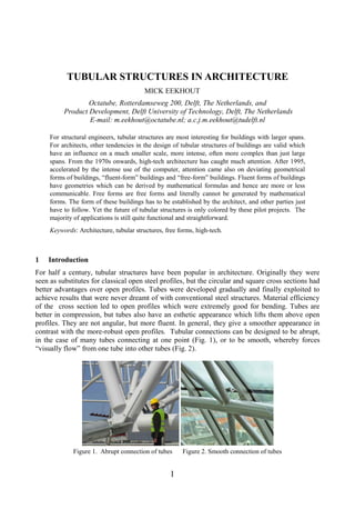
  • 1. 1 TUBULAR STRUCTURES IN ARCHITECTURE MICK EEKHOUT Octatube, Rotterdamseweg 200, Delft, The Netherlands, and Product Development, Delft University of Technology, Delft, The Netherlands E-mail: m.eekhout@octatube.nl; a.c.j.m.eekhout@tudelft.nl For structural engineers, tubular structures are most interesting for buildings with larger spans. For architects, other tendencies in the design of tubular structures of buildings are valid which have an influence on a much smaller scale, more intense, often more complex than just large spans. From the 1970s onwards, high-tech architecture has caught much attention. After 1995, accelerated by the intense use of the computer, attention came also on deviating geometrical forms of buildings, “fluent-form” buildings and “free-form” buildings. Fluent forms of buildings have geometries which can be derived by mathematical formulas and hence are more or less communicable. Free forms are free forms and literally cannot be generated by mathematical forms. The form of these buildings has to be established by the architect, and other parties just have to follow. Yet the future of tubular structures is only colored by these pilot projects. The majority of applications is still quite functional and straightforward. Keywords: Architecture, tubular structures, free forms, high-tech. 1 Introduction For half a century, tubular structures have been popular in architecture. Originally they were seen as substitutes for classical open steel profiles, but the circular and square cross sections had better advantages over open profiles. Tubes were developed gradually and finally exploited to achieve results that were never dreamt of with conventional steel structures. Material efficiency of the cross section led to open profiles which were extremely good for bending. Tubes are better in compression, but tubes also have an esthetic appearance which lifts them above open profiles. They are not angular, but more fluent. In general, they give a smoother appearance in contrast with the more-robust open profiles. Tubular connections can be designed to be abrupt, in the case of many tubes connecting at one point (Fig. 1), or to be smooth, whereby forces “visually flow” from one tube into other tubes (Fig. 2). Figure 1. Abrupt connection of tubes Figure 2. Smooth connection of tubes
  • 2. Eekhout, M. 2 The development of tubular structures, in particular for large spans, has been guided by structural engineers not only by their pure function as load-bearing structures, but has also been increasingly influenced by architectural engineers with more design considerations involved. 2 Product development of tubular structures The time of standard products seems to be over. In the trio of standard products, system products and special products in product development, system products like space frame structures are almost past. Architects want to design their own structures, with a remarkable project characteristic. From the experience with system products we know the base of system products are half-products like steel tubes and pipes, which get a free form production treatment, often maltreatment: cornering, bending and curving, all to transform simple straightforward steel tubes into ingenious tubular components, each with their own form and connections, but at a cost. We can apparently afford this as we are living in quite a luxurious world. Despite this reasoning in general, in the last decade regular geometric structures were the favourite and still make up the vast majority of buildings nowadays. It is the rational structural design towards minimal material use, combined with repetition in production and assembly, that makes economic structures. Frei Otto was the pioneer of minimal structures, leading to his membrane and cable net structures of the 60s and 70s (Fig. 3) with complete separation of tensile forces (in membranes and cables) and compression forces (in masts and foundations). Figure 3. Olympic Stadium Munich, Frei Otto, Günther Behnish Extreme separation of forces leads to heavy foundation anchorings, out of sight, which do not directly follow the laws of minimal material use because of larger bending moments than usual. In effect, the use of minimal material has been lost ever since the “Bird’s Nest” of Beijing, China (2008), Fig. 4, which consumed eight times the amount of steel compared to a regular stadium of the same size. Figure 4. National Stadium ‘Bird’s nest’ Beijing, Herzog & De Meuron
  • 3. 17th International Symposium on Tubular Structures (ISTS17) 3 However, economic structures do not make a winner at competitions when the jury knows that many more geometries are possible. Architects get bored by predictable regular geometries. They want to design and not just obey the laws of regularity in geometry. They want to win a design competition by astonishing the jury or the client. The omnipotent abilities of computer rendering, and later structural analysis by computer, make tubular structures very suitable for structural manipulations. Irregularity, because of architectonic reasons, became more experimental for architects in order to win design competitions with designs that amaze the jury, and later the world. Designs of new stadiums (e.g. Fig. 5) prove this. Figure 5. Design Competition for 2020 Olympics: National Stadium Tokyo, Zaha Hadid 3 High-tech structures In 1997 the CIDECT/TU Delft book “Tubular Structures in Architecture” was published in five languages and 25,000 copies were sold worldwide. In between the distinguished company of structural engineer and architect, the engineering architect or architectural engineer always has a different view. This resulted in the book “Tubular Structures in Architecture” which explained the possibilities, reasoning and realized examples of high-tech Architecture. Actually, high-tech architecture was introduced to the world with the Beaubourg Centre (Fig. 6) as an explosion “to change fashion in architecture” as the late Ted Happold, the collaborating engineer of Renzo Piano on the project, said at the LSA Conference in Sydney, in 1986. Figure 6. Centre Pompidou, Paris, Piano & Rogers
  • 4. Eekhout, M. 4 High-tech architecture became popular in the world after the Pompidou Centre in 1978. As it was, it turned the normal straightforward reasoning of structural engineers upside down. Why design an obvious and simple structure, when you can also design an astonishing, or even an exciting, structure? Nowadays, more than 20 years after the first issue of the book, a generation later, one could say that the book was written in the middle of the high-tech era. The structure of a building, as a load-bearing mechanism, had always been important in the design of buildings, but was never of much concern for architects. However, showing them the structural skeleton made structural design exciting for a whole generation of architects. Designing according to the bending moment distribution in a structure had its own appeal for architects. It made structures even more understandable and prominent for the observer, and for the user of buildings. In many structural high-tech designs the separation of tensile forces and compression forces plays a visual role, sometimes even exaggerated as a show-off. The book was written, however, on realised hand-designed structures, with hand-engineered details and shop drawings. Sometimes it was a wonder that, without exacting surveying apparatus, these prefabricated structures fitted in reality to the millimeter. The eleven roof segments of the 50 m space frame for the Aquadome in Bremen (Figure 7) were installed, but would the closing segment number 12 fit? It actually did, the open space for segment number 12 was 3 mm too wide, which was easy to be filled. It was exciting like a rocket launch! Figure 7. Aquadrome Bremen, Hamming High-tech structures often were products of a deliberate collaboration between the architect and the structural designers in one project, a collaboration more intense than before. Architects understood high-tech structures. Kanzai Airport (Fig. 8) designed by architect Renzo Piano and structural engineer Peter Rice marked a moment in time in a cross-over towards complex geometry design. The design followed a complicated geometrical form with a large radius for the roof form. Producers who had underestimated the complexity of these tubular design structures could easily suffer gigantic losses on these early free-form architectural projects. Figure 8. Kanzai Airport, Osaka, Renzo Piano
  • 5. 17th International Symposium on Tubular Structures (ISTS17) 5 4 Sculptural designs and free-form structures Only 15 years later, in 2011, the second and extended edition of “Tubular Structures in Architecture” was written and published. Drawing tables had already been removed from architects’ offices. The influence of the computer in architectural offices was amazing. The computer was seen initially as a substitute for boring or complicated hand-made designing and engineering. From the mid-1990s the use of computer programs in the architect’s office gave unexpected and exciting results. After confirmation of the flawless geometrical computation capacity of computer programs, more complicated designs enabled more complex geometries to be realised. The introduction of the computer evoked more complex designs (e.g. Fig. 9) in tubular structures than were ever-possible to be realised. Figure 9. A complex tubular structure; Guillemins, Luik, Santiago Calatrava 4.1 The Guggenheim museum in Bilbao was the start of free-form architecture The transition in architectural geometry was dramatically pointed in history by the Guggenheim Museum, designed by Frank Gehry, and realised in 1997 (Fig. 10). It was the flagship of free- form architecture. I remember the first time I saw it, when giving a lecture in Bilbao on the issue of “Tubular Structures in Architecture; I had to adapt my carousel slides. The museum had come like a satellite from outer space, landed in Bilbao and changed the outlook of the entire city. A building under construction for a shopping centre, a bit further down the river, all of a sudden looked helplessly old-fashioned, almost 1960s. So just one building changed the outlook and the future of an entire city. A former industrial harbor city all of a sudden became the world place to be for tourists. Bilbao is Guggenheim and Guggenheim is Bilbao. Figure 10. The new appearance of the Guggenheim Museum, Bilbao, Frank Gehry
  • 6. Eekhout, M. 6 But the technology employed for this building was outdated. Photographs of the construction work were hardly published. Open profiles had large connection plates and all members were welded on the site, so that they would fit (Fig. 11). It was building a new design with old- fashioned ingredients. Maybe Gehry had been shocked by the performance on site, because in his next project he became more fierce with his explicit design engineering. Figure 11. Load-bearing structure of Guggenheim Bilbao during construction phase 4.2 Risky design developments as moonshots Bold architects even went so far as to even design free-form structures that were impossible to be built, before computerisation of the architectural designs (Fig. 12). Free-form structures cannot be generated by mathematical formulas. But too-early adopting and too-eager architects saw mishappenings. Designs by architects without knowledge of adapted execution in production and on site either caused projects to be cancelled, architects put on the blacklist of clients, unfortunate production parties to go bankrupt, and the near-bankruptcy of Europe’s most famous curtain wall company, Gartner (taken over by Permasteelisa). Figure 12. Structural proposal for Wilhelmina Pier, Zwarts & Jansma We say now: these architects were light years ahead of their time. Sometimes they were much too early and under-estimated the capacities of the production industry to execute their designs, without any prior knowledge gained from previous projects, as there were no prior projects.
  • 7. 17th International Symposium on Tubular Structures (ISTS17) 7 Figure 13. Deutsche Genossenschaft Bank Berlin, Frank Gehry For production companies these “moonshots” (e.g. Fig. 14), which are very complicated projects with an aim, but without appropriate knowledge and no prior experience, can be fatal and can lead to bankruptcy. Usually producers say: the architect is praised and the churchyard is full of “naïve losers” and other disillusioned contractors. So, free-form architecture and the shortage of experience and proper production efficiencies also led to a number of economic failures. Figure 14. Rabin Center, Tel Aviv, a personal “moonshot” project, Moshe Safdie. Gradually, after a number of abortive projects, then a number of barely successful projects, and after publications on the required and more-or-less (economically) successful free-form technology, more projects were realised. As always, design-eager architects and wealthy clients were praised. It led to understanding and further development of the required free-form technology. The road to success is paved with many “moonshot” gravestones of producers. After many free-form structures, one could notice that the adage of light-weight structural design, as in the “minimal material” era of Frei Otto, was forgotten and was been exchanged by heavy and moment-resistant structures (see the form-driven of free-form designs of Frank Gehry, Fig. 15).
  • 8. Eekhout, M. 8 Figure 15. Louis Vuitton Museum Paris, Frank Gehry 4.3 Prototyping to get acquainted with new technologies An alternative for the initial absence of appropriate knowledge in this upcoming new field of expertise was to make use of material prototypes, to be built during the design process or engineering process. Prototypes (Figs. 16 and 17) designed and engineered by the architect and structural engineer would reveal to the offices many uncertainties and secrets that cannot be seen from computer models, not even the most advanced types. Small details are worthwhile being made in real materials, manipulated in the hands of the designers to get accustomed to the real material, real sizes and the weight of material details. There are always material flaws. Large- scale prototypes cost extra money, of course. Dutch clients do not want at all to invest in such prototypes, as they see it as superfluous energy and investment. In America and in Asia, however, we have experienced that making prototypes is often a more-common practice.
  • 9. 17th International Symposium on Tubular Structures (ISTS17) 9 Figure 16. Prototype of AFAS Dome at Octatube Figure 17. Testing of mock-up in Tokyo From prototypes, not only can one party learn but all involved as partners in a design team can gain. Also, if performed before a tender is issued, all tendering parties could draw upon their lesson which prevents “wild-west tendering”. In many projects the client can prevent losing much money, as such prototyping is seen as enabling efficiencies for the entire process. Figure 18. Tubular space frame in the roof of Raffles City, Singapore In other cases, internal rivalries within a building design development and engineering team could be settled more easily when everyone’s mutual experience was visual. Also, prototypes could help to prevent a loss of time. Buildings with complex geometries benefit from prototyping, as “nothing is normal”.
  • 10. Eekhout, M. 10 Figure 19. Octatube’s alternative design of the Deutsche Genossenschaft Bank Berlin, Frank Gehry 4.3 Frontrunners Architects who were working enthusiastically at the forefront of new development of free-form design were only retarded by the production and construction industry, who had no idea how to make free-form constructions with elements and components that deviated from simple tubes and nodes. Architects and engineers did not collaborate with producers to develop free-form production technology. They expected that throwing an invitation for tender “over the wall” would automatically generate success. Well, at first it harvested impossible prices and generated much misunderstanding. Figure 20. Elevation of the 45 x 75 m-large Mediatheque’s roof structure by Octatube, Zaha Hadid They said: “The industry could not cope”, et cetera. Dreaming on computer-aided manipulative geometries went far beyond the imagination and the usual, experienced capacity of the producing parties. They could not diminish the many risks involved. 4.3 Self-overestimation or “moonshot” thinking? In 1962, President John F. Kennedy gave a speech: “We choose to go to the moon in this decade”, and that was the beginning of the ambition of an entire nation to reach the moon. We could say that JFK did not set that goal by knowing how we could achieve it, or by promising that it would be easy; he simply said that we were going to accomplish something incredible, setting the timeframe and inspiration towards action. The money would come later. In the case of the Rabin project (Fig. 14) my company Octatube and I had to overcome a “moonshot” with as much as eight innovations packed into one project (Fig. 21):
  • 11. 17th International Symposium on Tubular Structures (ISTS17) 11  Glass-fibre-reinforced polyester;  Free-form architecture;  New computer programing;  All elements and components integrated into a big BIM model;  Large smooth surfaces required;  Innovative production out of our sight, in a specialist factory;  Hostile attitude from the Israeli approving officials;  Assembly out of sight, 5000 km from the office. Figure 21. “Moonshot”-project Rabin Centre; eight innovations in one project This obviously led to an almost-unmanageable, technically innovative project. “Moonshot thinking” is derived from NASA working with limitless governmental budgets, unlike the discrete budgets in projects or companies which are restricted, as are a company’s limits. With only a few projects per year in any country, the eagerness amongst producers to adapt their production capacities in their own companies was not overwhelming. However, for large pilot projects, and especially prominent projects, money was available to adapt production technology by introducing computer-aided manufacturing, by introducing associated assembly methods with a main focus on geometric surveying. Architects like Frank Gehry had obviously learned from the Guggenheim and dictated, in this millennium, their own specifications for the design of free-form components. Gehry specifically requests his buildings to be built as he has designed and engineered, with no alternatives possible (Fig. 15). 4.4 Producers or specialist contractors? Some manufacturers developed their own “vocabulary” in order to have a technical answer to free-form architectural designs. Usually these designs are quite large and, within the development of a project, there is space and money available to develop new production vocabulary for each new free-form project. With many experiences in the Octatube office, as illustrated in this publication, the technical engineering of a free-form architectural design often follows a particular project characteristic.
  • 12. Eekhout, M. 12 Figure 22. Design Proposal for Capital C, Diamond Beurs Amsterdam Figure 23. Construction photograph of Rokin cylindrical roof, Amsterdam, Rijnboutt All architectural designs are different. The architect wants to achieve the “first-on-the-block effect”: a first-car lover wants a pink Cadillac. The second buyer will never want a pink Cadillac as he does not want to copy the forerunner. An architect never wants to be seen as an imitator or an adaptor of another architect from a previous project, but always strives to be purely original. This does not lead to systems engineering and production; it leads to “Industrialisation in units of one”. Most of the experience from earlier designs cannot be directly or literally used in a next project. What remains are the willingness to perform free-form technology, to exploit the process experiences from earlier projects, and the free-form engineering attitude. The goal is to have computer programs inter-relating between architectural design, component engineering, production machining, and geometric surveying of components in their expected positions on site; but attitude and experience come first. My own professional part, as an architect in the world of structural designers and structural engineers, led me to develop a new “vocabulary” for space frame structures with tubular components, and later for glass structures, by undertaking many successive “design & build” projects. Rather small projects were attempted at first, with clear or restricted risks, using an incremental approach. “Step by step”, as Piano once wrote. As a design engineer, never throw an impossible design over the fence and expect that it will work. Misinformation from the
  • 13. 17th International Symposium on Tubular Structures (ISTS17) 13 designing parties, misunderstanding, misinterpretation and lack of motivation from the side of producers, do not lead to successful answers by producers in the tender processes. When you, as a design engineer, do not know how your design has to be made, don’t expect others to take up that risk either. 5 Complex Tech-Architecture  Tubular designs are visual designs that are pleasing to the eye;  Tubular structures are easy to be manipulated in the design phase: bent or curved;  The geometry of tubular steel structures is increasing in complexity due to design manipulations with the aid of computer programs;  Tubular structures become an integrated part of the building envelope;  Complex detailing beyond the structural function is required around tubular structures. Architects have a tendency to make “basic” tubular structures more complex by using exterior and interior cladding and glazing, by mixing tubular steel structures with other structural materials like glass, by adding more functions like sound absorption, and by designing project- typical structures. Perhaps the best drive in the continuous quest for disruptive innovations in tubular structures results from curiosity, creativity, persistence, a bit of naivety, a positive spirit and belief in ambitions, and, of course, the joy in making new things that last. 6 Examples of projects from regular to irregular geometry 6.1 Air Traffic Control Leader bridge, Schiphol Airport, NL
  • 14. Eekhout, M. 14 Figure 24. Air Traffic Control Leader bridge, Ector Hoogstad Air Traffic Control Leader bridge at Schiphol Airport, a pedestrian bridge of 50 m span between two buildings at Schiphol Airport, Amsterdam, is made of square or circular hollow sections (CHS) in a regular structural system. The original design showed a cigar-shaped form with a wider cross section in the middle of the span and a smaller cross section at both connecting ends. However, this cigar-form was substituted by a straight elliptical form for cost reasons. It saved approximately 30% on the total budget of the tubular structure, sandwich claddings and glazing panels together. Architect: Ector Hoogstad Architecten 6.2. AFAS Dome, Leusden, NL Figure 25. AFAS Dome, Leusden, NL, Van der Velt & Just Architects AFAS Dome, Leusden, NL, is a regular network dome made in CHS with welded connections, highly sophisticated glass cladding, and internal cabling for lighting, computing and fixtures. The dome is under construction at the time of writing. The model (fig. 16) shows that the connections are made as rigid, bolted connections with four internal bolts. In the centre of the CHS tubes there is enough space for electrical cables. Architect: Van der Velt / Just Architects. 6.3. Friesland Bank Dome, Leeuwarden, NL Friesland Bank Dome, Leeuwarden, the Netherlands. A dome structure in a regular geometry, but suspended from three arches, as the foundation only allows three foundation anchorage points between existing buildings. The dome structure is also loaded by a large flat roof on one side, at the side of the open atrium. Which makes it a heavily loaded, suspended dome. Architect Aat van Tilburg, Rotterdam / Harmen Grunstra, Bolsward.
  • 15. 17th International Symposium on Tubular Structures (ISTS17) 15 Figure 26. Friesland Bank Dome, Aat van Tilburg 6.4 Hudson Bay, Amsterdam, NL Figure 27. Hudson Bay, Rijnboutt Hudson Bay, Amsterdam, has a top floor restaurant, with a beautiful sight overlooking the centre of Amsterdam. The form of the tubular structure takes a regular cylindrical shape made of rectangular hollow sections (RHS) which have a slight twist incorporated in the connections to amaze the world with a diagonal geometry instead of the usual orthogonal geometry. It gives the indoor space a “swing”. Architect: Rijnboutt.
  • 16. Eekhout, M. 16 6.5. The Southgate Canopy, Delft, NL Figure 28. Southgate Canopy, Mick Eekhout The Southgate canopy in Delft has been made in a waving system of CHS, specifically to show the possibilities of cold-warping of laminated glass made with flat and orthogonal glass panels. Architect: Mick Eekhout 6.6. London Business School, London, UK Figure 29. London Business School, Sheppard Robson London Business School, London, has two intermediate glazed spaces with specially made triangular hollow sections in an irregular composition. The triangular hollow sections leave no shadow at their lower side. They leave attention for the three existing Victorian buildings which they connect. Architect: Sheppard Robson. 6.7. Glass House, Malmö, Sweden The Glass House of Malmö has a smooth form made entirely of flat glass panels, supported by a waving structure of CHS tubes in an elliptical form with a connecting rib at the top. Design: Monica Gora and Ian Liddell / Happold, Engineering by Octatube.
  • 17. 17th International Symposium on Tubular Structures (ISTS17) 17 Figure 30. Glass House, Malmö, Monica Gora The design challenge was to engineer this principally fluid form, as in the plexiglass model, to become a structure with preferably flat glass panels, not with hot-bent or cold-bent glass. The solution was to make a series of arches almost perpendicular to the surface of the glass skin. This skin became a polygonal surface, made of flat-glass panels. All corners are different, so the “Quattro” nodes connecting the tubular structure with the glass panels were all individually made in a different form. From the choice of single laminated glass or insulated glass panels, both laminated, the client made her choice for single glass for maximum transparency. Design: Monica Gora and Ian Liddell / Happold. 6.8. Van Gogh Museum Entrance Hall, Amsterdam, NL Figure 31. Van Gogh Museum, Amsterdam, Hans van Heeswijk
  • 18. Eekhout, M. 18 The Van Gogh Museum Entrance Hall in Amsterdam has only a basic structure consisting of two free-formed CHS on seven CHS columns, with steel shoes to fit in the laminated glass fins which were produced in China. The shoes thus had to be provided to a very high accuracy, of only a few millimeters, which is seldom in free-form. The two tubes are 3D bent. Architect: Hans van Heeswijk. 6.9. Diamond Exchange Building, Amsterdam, NL Figure 32. Diamond Exchange Building, Amsterdam, Zwarts & Jansma The Diamond Exchange Building in Amsterdam has been provided with a free-formed grid as a topping-up shell roof made of RHS. The system was made in the form of a square single-layered grid of which each member and each node was different because of the free-form geometry. The shell has been made in the form of separate ladders, welded on an accurate mold, with singular members in-between, bolted on site. Architect: Zwarts & Jansma. 6.10 Notre Dame, Paris, France On April 15, 2019, the roof of the Notre Dame cathedral in Paris burned off completely, including the central roof tower. The roof construction was entirely built of oak wood, more than eight centuries old. All over Europe medieval churches have timber roof structures that occasionally ignite after maintenance activities. Insufficient fire prevention measures can be quite expensive in the long run. France will organize an international architectural competition, in which the obvious discussion between tradition and amazing innovations will no doubt be celebrated. The technical solution, however, is simple. The plan of the cathedral is made of modules 7.5 x 15 m, with the central module in the crossing being 15 x 15 m. This makes it ideal for an old- fashioned tubular space frame. The roof angle of 55º leads to a very regular space frame in a cross form with 15 m-long tubular elements, which can be refined up to a module size of 7.5 x 7.5 m². The advantage is that a three-dimensional space fame has a large rigidity in both directions of the plan and on all of its support points. Many of these support points, also being the tops of the flying buttresses, have had a high thermal attack during the roof fire and can be supposed to have been bent outwards. The nodal points of this space frame can bring the entity of the tops of the load-bearing masonry construction to rest, either by fixing, or even by post- bending backwards to relieve the extra compressions caused by the fire.
  • 19. 17th International Symposium on Tubular Structures (ISTS17) 19 Figure 33. Possible roof structure with a standard space frame as an exactly fitting tubular roof structure The tower or “Fleche” from the time of Viollet le Duc around 1850 had a timber load-bearing structure. It collapsed during the fire and punched through the cross vault, which is now open. The other masonry vaults are still more-or-less in order. A new tower of a vertical design can be imagined rising from the four diagonal-angle rafters, having fixed connections on the bottom level and on the ridge of the space frame at its crossing. Many tower designs are possible, straight upward or twisted. The space frame with member lengths of 15 m can also be subdivided into lengths of 7.5 m, which will make the individual tubular members lighter. At the vertical center of the space frame, on the horizontal cross members of the space frame, a walkway can be realised at half-height of the roof volume. On the outside of the space frame metal purlins will be connected with an interspace convenient for the cladding to be chosen. The cladding can be made, as it has been for centuries, by lead panels on purlins, but this time not with timber but steel purlins. Alternatively a roof cladding material like glass could be chosen. However, in relation to the century-old lead material, glass materials age quicker. In comparison with long-lasting lead panels, double-glass panels with a factory guarantee of only 10 or 20 years do not seem appropriate for a building that has to survive again the coming centuries. It would, though, allow the possibility to have daylight enter into the central vault, even if only small cladding surfaces were made of glass. The central cross vault has been punched through by the collapsing central spire. This central vault could be reconstructed by solid glass blocks, functioning as a brick vault, but now allowing daylight to enter into the cathedral. The cathedral could get another daylight focus in the center of the cross-formed plan, a completely new concept for a gothic cathedral. So tubular structures can contribute in a modest way to the restoration of a famous cultural building.
  • 20. Eekhout, M. 20 7. Conclusions for the Architectural Future of Tubular Structures The architectural future of tubular structures is different from its structural and industrial use. In the domain of structural engineers and tube producers, the vision of architects and designers, illustrated by their proposals and realized projects, illustrates the state of the art of the architecture of tubular structures. The multitude of tubular applications is quite straightforward. However, architectural innovative design thinking leads the way forward qualitatively. The era of high-tech structures, with their rather mechanically steered geometry, is apparently over. The era of free-form structures has introduced complexity and complication in geometry. After two decades of trial and error it has been split into fluent-form and free-form structures. Fluent form has a communicable geometry because of the mathematics behind it, however complex that may be. Free-form structures are really sculptural structures which are conceived by the designer as a sculptor, without any mathematics behind them. Many of the complicated structures of Frank Gehry are free-formed from random folded paper props, that are “frozen” from the moment they leave the table of the handicraft master. They are measured and then put into a strictly obeying geometry. It is no wonder that engineering, producing and realizing parties have to purchase the same computer programs (i.e. Catia) that Gehry Associates use in their design, to assure that the engineered geometry is exactly the designed one, which they can supervise. In following this approach Gehry remains master of the game, all the way through to the opening of the building. However, it is a demanding approach for the executing parties. Free-form geometries are expensive to realize. In the case of the Rabin Center in Tel Aviv, architect Moshe Safdi gave a “free-form” model, which had to be adjusted and refined. It was drawn in a 3D model which could only be handled by one particular engineer. This project followed a similar route of development as Gehry’s design and engineering development. Fluent-form designs (composed from complex mathematical models), have less problems with communication. These forms can be mathematically generated by different parties involved in the building team of a project. A wise architect sells a competition-winning design as a free form design but generates it towards realization as a fluent design. The more repetition, the more economic the structure will be. Buildings with “industrialization in lots of one”, can be made, but at a cost. In all, architects are very interested in the more sculptural architectural designs than just straight-forward designs. Tubular structures have excellent characteristics to be handled as sculptural structures, and to be pleasing to the eye. Acknowledgments It is a great honor to have been asked by Sub-commission XV-E of the International Institute of Welding to present this “Kurobane Lecture” at the 17th International Symposium on Tubular Structures, here in Singapore. Also, I would like to express my sincere thanks to Professor Jaap Wardenier for being a very understanding structural engineering colleague and good friend. References Eekhout, M., Tubular Structures in Architecture, 2nd Ed., ISBN 978-944-90675-01-1, CIDECT, Geneva, 2011.