Energy Calculator for Usage Monitoring
•
1 like•418 views

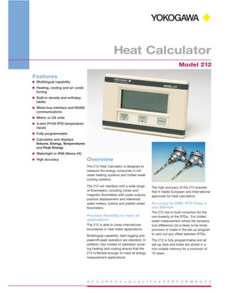
The Model 212 Heat Calculator is designed to measure the energy consumed in both heating and cooling (air conditioning) systems. The instrument is normally supplied complete with temperature probes and power supply, and will interface to a wide variety of flowmeters, including positive displacement and inferential water meters, magnetic flowmeters with pulse outputs, turbine flowmeters & paddlewheel flowmeters. The Model 212 measures the temperature in the feed and return flow lines and uses this information to calculate the density and enthalpy of water. By also measuring the volume of water flowing in the system, the Model 212 will then determine the energy used.

Recommended
More Related Content
What's hot
What's hot (20)
Viewers also liked
Viewers also liked (19)
Similar to Energy Calculator for Usage Monitoring
Similar to Energy Calculator for Usage Monitoring (20)
More from Classic Controls, Inc.
More from Classic Controls, Inc. (20)
Recently uploaded
Recently uploaded (20)
Energy Calculator for Usage Monitoring
- 1. A C C U R A C Y • Q U A L I T Y • P E R F O R M A N C E Heat Calculator Model 212 Features I Multilingual capability I Heating, cooling and air condi- tioning I Built-in density and enthalpy tables I Meter-bus interface and RS485 communications I Metric or US units I 4-wire Pt100 RTD temperature inputs I Fully programmable I Calculates and displays Volume, Energy, Temperatures and Peak Energy I Watertight to IP66 (Nema 4X) I High accuracy Overview The 212 Heat Calculator is designed to measure the energy consumed in hot water heating systems and chilled water cooling systems. The 212 will interface with a wide range of flowmeters, including vortex and magnetic flowmeters with pulse outputs, positive displacement and inferential water meters, turbine and paddle wheel flowmeters. Provides flexibility to meet all applications The 212 is able to cross international boundaries in heat meter applications. Multilingual capability, data logging and peak/off-peak operation are standard. In addition, four modes of operation cover- ing heating and cooling ensure that the 212 is flexible enough to meet all energy measurement applications. The high accuracy of the 212 ensures that it meets European and International approvals for heat calculators. Accuracy to OIML R75 Class 4 and EN1434 The 212 has in-built correction for the non-linearity of the RTDs. For chilled water measurement where the tempera- ture difference (∆t) is likely to be small, provision is made in the set-up program to zero out any offset between RTDs. The 212 is fully programmable and all set-up data and totals are stored in a non-volatile memory for a minimum of 10 years.
- 2. Watertight wall or panel mount enclosure The 212 Heat Calculator is housed in a rugged yet attractive IP66 (Nema 4X) rated polycarbonate enclosure which is completely watertight. Mounting is either by a wall bracket or by panel mount. Integration with energy manage- ment systems A Meter-bus interface enables the 212 Heat Calculator to be incorporated into energy management systems complying with European IEC 870-5 protocol stan- dards. The 212 is also supplied with an RS485 bus, which uses industry standard Modbus RTU protocol, for interfacing to computers and DCS systems. Datalogging flexibility The 212 Heat Calculator will store ener- gy totals by hour, day, week or month for up to 31 periods. The totals are stored for each period and can be downloaded to a computer via the Meter-bus or RS485 communications ports. Peak and off-peak registers If selected, the peak/off-peak feature will assign two separate registers which will totalize peak energy and off-peak energy. The changeover times between peak and off-peak are fully programmable. Modes of Operation The 212 Heat Calculator is flexible enough to handle a wide range of appli- cations. Four operating modes are avail- able. I Heating Mode where positive ∆t's only are totalized. I Cooling Mode where negative ∆t's only are totalized. I Heating/Cooling Mode where the flow of energy may be for heating or cooling. In this mode the energy total is increased regardless of whether ∆t is positive or negative. I Charge/Discharge Mode where two separate registers totalize positive and negative totals. Calculates the density and enthalpy of water The 212 Heat Meter measures the tem- perature in the feed and return lines and, from this, calculates the density and enthalpy of the water. By also measuring the volume of water flowing in the system, the 212 will then compute the energy consumed. Power is calculated as: P = V x pp x (hTV - hTR) where P = Power (W) V = Volumetric flow rate (m3 /s) pp = Density (kg/m3 ) hTV = Specific enthalpy (J/kg) at Feed temperature hTR = Specific enthalpy(J/kg) at Return temperature The volume, energy, temperatures and peak energy are all calculated and can be displayed on the large LCD. Heat Calculator Model 212 A C C U R A C Y • Q U A L I T Y • P E R F O R M A N C E
- 3. General Display Type: 7 digit LCD - 7 numeric digits and 11 alpha characters. Digits: 15.5mm (0.6”) high. Characters: 6mm (0.24”) high. Display Units: kWh, MWh, MJ, GJ, therm, BTU x 1000, tons x hours (refrigeration). Maximum Thermal Power 3000MW Measurement Time 0.3s. Accuracy OIML R75 Class 4 and EN 1434. Power Requirements DC Power: 12 to 24V DC @ 100mA maximum. Physical Temperature Operating: 5 to 55°C. Storage: -20 to 70ºC. Environmental Class EN1434 Classes A & C. Enclosure Protection: IP66 (Nema 4X) watertight. Materials: Polycarbonate and ABS. Mounting Options Wall: Wall mount bracket. Panel: Mounting clips. Inputs Flowmeter Type: Frequency or pulse between 0.01Hz to 20KHz. Default low frequency cutoff is 0.25Hz. K-factor Range: Programmable in the range 0.001 to 999,999.9 pulses per litre, m 3 , US gallon or ft3 . Signal Type: Pulse, open collector, reed switch, proximi- ty switch or coil. Location: In either the return or feed lines. Temperature Type: 4-wire Pt100 RTDs to IEC 751. 1 /10 DIN. Location: 1 x Feed Line and 1 x Return Line. Linearisation: Built-in RTD linearisation. Temp. Range: -10 to 220°C (1 to 200°C approved). Temp. Difference: 1 to 200K (2 to 199K approved). Measurement Time: 15s Cable Length: <50m. Connection: G1/2B. Outputs Pulse Type: Open collector will sink up to 100mA, 30V DC maximum. Width: 10ms. Function: Volume or Energy (scaled). Frequency: 1 pulse every preset number of units of energy or volume total. Alarm Type: Two solid state opto-isolated relays which will sink up to 100mA, 30V DC maximum. Function: High and low alarms individually programmable as unsigned values for flow rate, energy flow rate, feed temperature, return temperature or temperature difference. Meter-Bus Type: Conforms to CEN/TC176 Meter-bus standard. Protocol: IEC 870-5. RS485 Data Transmitted: All data calculated can be transmitted. Baud Rate: 300 to 9600 baud. Parity: Odd, even or none. Stop Bits: One or two. Bus Address: Programmable for multiple instruments on the same bus. Protocol: Modbus RTU. Important: Specifications are subject to change without notice. Specifications 152mm (6.0") 96mm (3.9") 141mm (5.6") REAR VIEW SIDE VIEW 87mm (3.5") 16mm (0.6") 96mm (3.9") Dimension Drawings c
- 4. Distributed by: Terminal Descriptions D Ordering Information When specifying please indicate model(s) required using the following method. 4 Dart Road Newnan, Georgia Tel: 1-770-254-0400 Fax: 1-770-251-6427 www.yokogawa-ia.com BU 1P11A2-E-U REV 1, JULY 1998