SlideShare a Scribd company logo
1 of 50
Coordinate Measuring
Machine (CMM)
S.DHARANI KUMAR
Asst.professor
Department of Mechanical Engineering
SRI ESHWAR COLLEGE OF ENGINEERING
,COIMBATORE ,INDIA
TYPES OF MEASURING MACHINES
1. Length bar measuring machine.
2. Newall measuring machine.
3. Universal measuring machine.
4. Co-ordinate measuring machine.
5. Computer controlled co-ordinate measuring machine.
Coordinate Measuring Machines
• Coordinate metrology is concerned with the measurement
of the actual shape and dimensions of an object and
comparing these with the desired shape and dimensions.
• In this connection, coordinate metrology consists of the
evaluation of the location, orientation, dimensions, and
geometry of the part or object.
• A Coordinate Measuring Machine (CMM) is an
electromechanical system designed to perform coordinate
metrology.
Coordinate Measuring Machine (CMM)
Measuring machine consisting of a contact probe and a mechanism to position
the probe in three-dimensions relative to surfaces and features of a work part
The probe is fastened to a structure that allows movement relative to the part
Part is fixture on worktable connected to structure
The location coordinates of the probe can be accurately recorded as it contacts
the part surface to obtain part geometry data
Coordinate Measuring Machines
• A CMM consists of a constant probe that can be positioned in 3D space
relative to the surface of a work part, and the x, y, and z coordinates of the
probe can be accurately and precisely recorded to obtain dimensional data
concerning the part geometry
accomplish measurements in 3D, a basic CMM is composed of the following
components:
 Probe head and probe to contact the work part surface.
 Mechanical structure that provides motion of the probe in three Cartesian axes
and displacement transducers to measure the coordinate values of each axis.
• In addition, many CMM have the following components:
 Drive system and control unit to move each of the three axes
 Digital computer system with application software.
Coordinate Measuring Machines
CMM
CMM – Coordinate Measuring Machine
Flatness
Roundness
Cylindricity
CMM Mechanical Structure
(a) Cantilever (b) Moving bridge (c) Fixed bridge
CMM Mechanical Structure
(d) Horizontal Arm (e) Gantry (f) Column
Cantilever type
• A vertical probe moves in the z-axis
• Carried by a cantilevered arm that moves in the y-axis
• This arm also moves laterally through the x-axis
• Advantage- a fixed table allows good accessibility to the
work piece
• Disadvantage- the bending caused by the cantilever design
• The cantilever design offers a long table with relatively
small measuring ranges in the other two axis.
• Suitable for measuring long, thin part
Moving bridge type
• Most widely used
• Has stationary table to support work piece to be
measured and a moving bridge
• Disadvantage- with this design, the phenomenon of
yawing (sometimes called walking) can occur- affect
the accuracy
• Advantage- reduce bending effect
Fixed bridge type
• In the fixed bridge configuration, the bridge is
rigidly attached to the machine bed
• This design eliminates the phenomenon of
walking and provides high rigidity
Column type
• Often referred to as universal measuring
machine instead of CMM
• The column type CMM construction provides
exceptional rigidity and accuracy
• These machines are usually reserved for gauge
rooms rather than inspection
Horizontal arm type
• Unlike the previous machines, the basic horizontal
arm-type CMM
• Also referred to as layout machine
• Has a moving arm, and the probe is carried along the
y-axis
• Advantage- provides a large area, unobstructed work
area
• Ideal configuration for measurement of automobile
parts
Gantry type
• The support of work piece is independent of the x and y axes,
both are overhead, supported by four vertical columns rising
from the floor
• This setup allows you to walk along the work piece with the
probe, which is helpful for extremely large pieces
CMM Operation and Programming
• Positioning the probe relative to the part can be accomplished in several ways, ranging from
manual operation to direct computer control.
• Computer-controlled CMMs operate much like CNC machine tools, and these machines must
be programmed.
CMM Controls
• The methods of operating and controlling a CMM can be classified into four main
categories:
1. Manual drive,
2. Manual drive with computer-assisted data processing,
3. Motor drive with computer-assisted data processing, and
4. Direct Computer Control with computer-assisted data processing.
CMM Controls
• In manual drive CMM, the human operator physically move the probe along the
machine’s axes to make contact with the part and record the measurements.
• The measurements are provided by a digital readout, which the operator can
record either manually or with paper print out.
• Any calculations on the data must be made by the operator.
• A CMM with manual drive and computer-assisted data processing provides some data
processing and computational capability for performing the calculations required to
evaluate a give part feature.
• The types of data processing and computations range from simple conversioons between
units to more complicated geometry calculations, such as determining the angle between
two planes.
CMM Controls
• A motor-driven CMM with computer-assisted data processing uses electric motors
to drive the probe along the machine axes under operator control.
• A joystick or similar device is used as the means of controlling the motion.
• Motor-driven CMMs are generally equipped with data processing to accomplish
the geometric computations required in feature assessment.
• A CMM with direct computer control (DCC) operates like a CNC machine tool. It
is motorized and the movements of the coordinate axes are controlled by a
dedicated computer under program control.
• The computer also performs the various data processing and calculation functions.
• As with a CNC machine tool, the DCC CMM requires part programming.
DCC CMM Programming
• There are twp principle methods of programming a DCC measuring machine:
1. Manual leadthrough method.
2. Off-line programming.
• In the Manual Lead through method, the operator leads the CMM probe through the various
motions required in the inspection sequence, indicating the points and surfaces that are to be
measured and recording these into the control memory.
• During regular operation, the CMM controller plays back the program to execute the inspection
procedure.
• Off-line Programming is accomplished in the manner of computer-assisted NC part
programming, The program is prepared off-line based on the part drawing and then
downloaded to the CMM controller for execution.
TYPES OF PROBES
• Two general categories
1. Contact (see figure)
• Touch-trigger probe
• Analog scanning probe
2. Noncontact
For inspection of printed circuit board, measuring a clay
of wax model, when the object being measured would
be deformed by the for of stylus
• laser probes
• video probes
Contact probes
1. Touch trigger probe
• As the sensor makes contact with the part, the difference in contact resistance indicates that
the probe has been deflected
• The computer records this contact point coordinate space
• An LED light and an audible signal usually indicate contact
• Touch probe assemblies consist of three components; probe head, probe and stylus
2. Analog scanning probe
• Use to measure contour surfaces, complex, irregular
• Remains in contact with the surface of the part as it moves
• Improve the speed and accuracy
Non-contact probe
1. Laser scanning probe
• Laser probes project a light beam onto the surface of a part
• When the light beam is triggered, the position of beam is read by triangulation through
a lens in the probe receptor
• Laser tool have a high degree of speed and accuracy
2. Video probe
• The feature are measured by computer ‘count’ of the pixels of the electronic image
• The camera is capable of generating multitude of measurements points within a single
video frame
Trigger type probe system
Measuring type probe system
Probe head, probes and stylus
Multiple shapes of sylus
CALIBRATION OF THREE CO-ORDINATE MEASURING MACHINE
APPLICATIONS
1) Co-ordinate measuring machines find applications in automobile, machine tool,
electronics, space and many other large companies.
2) These machines are best suited for the test and inspection of test equipment, gauges
and tools.
3) For aircraft and space vehicles, hundred percent inspections is carried out by using
CMM.
4) CMM can be used for determining dimensional accuracy of the components.
5) These are ideal for determination of shape and position, maximum metal condition,
linkage of results etc. which cannot do in conventional machines.
6) CMM can also be used for sorting tasks to achieve optimum pairing of components
within tolerance limits.
7) CMMs are also best for ensuring economic viability of NC machines by reducing
their
downtime for inspection results. They also help in reducing cost, rework cost at the
appropriate time with a suitable CMM.
ADVANTAGES
• The inspection rate is increased.
• Accuracy is more.
• Operators error can be minimized.
• Skill requirements of the operator is reduced.
• Reduced inspection fix Turing and maintenance cost.
• Reduction in calculating and recording time.
• Reduction in set up time.
• No need of separate go / no go gauges for each feature.
• Reduction of scrap and good part rejection.
• Reduction in off line analysis time.
DISADVANTAGES
• The table and probe may not be in perfect alignment.
• The probe may have run out.
• The probe moving in Z-axis may have some perpendicular errors.
• Probe while moving in X and Y direction may not be square to each
other.
• There may be errors in digital system.
CAUSES OF ERRORS IN CMM
• The table and probes are in imperfect alignment. The probes may have a degree of
run out and move up and down in the Z-axis may occur perpendicularity errors. So
CMM should be calibrated with master plates before using the machine.
• Dimensional errors of a CMM is influenced by
Straightness and perpendicularity of the guide ways.
Scale division and adjustment.
Probe length.
Probe system calibration, repeatability, zero point setting and reversal error.
Error due to digitization.
Environment
• Other errors can be controlled by the manufacture and minimized by the
measuring software. The length of the probe should be minimum to reduce
deflection.
• The weight of the work piece may change the geometry of the guide ways and
therefore, the work piece must not exceed maximum weight.
• Variation in temperature of CMM, specimen and measuring lab influence the
uncertainly of measurements.
• Translation errors occur from error in the scale division and error in straightness
perpendicular to the corresponding axis direction.
• Perpendicularity error occurs if three axes are not orthogonal.
Comparison between conventional and coordinate measuring
technology
CONVENTIONAL METROLOGY COORDINATE METROLOGY
Manual, time consuming alignment of the test piece Alignment of the test piece not necessary
Single purpose and multi-point measuring instruments
making it hard to adapt to changing measuring task
Simple adaptation to the measuring test by software
Comparison of measurement with material measures,
i.e., gauge block
Comparison of measurement with mathematical or
numerical value
Separate determination of size, form, location and
orientation with different machines
Determination of size, form, location and orientation in
one setup using one reference system
Features of CMM Software
• Measurement of diameter, center distance, length.
• Measurement of plane and spatial carvers.
• Minimum CNC programmed.
• Data communications.
• Digital input and output command.
• Program me for the measurement of spur, helical, bevel’ and hypoid
gears.
• Interface to CAD software
• Generally software packages contains some or all of the following capabilities:
1. Resolution selection
2. Conversion between SI and English (mm and inch)
3. Conversion of rectangular coordinates to polar coordinates
4. Axis scaling
5. Datum selection and reset
6. Circle center and diameter solution
7. Bolt-circle center and diameter
8. Save and recall previous datum
9. Nominal and tolerance entry
10. Out-of tolerance computation
CMM
CMM – Coordinate Measuring Machine
CMM
CMM – Coordinate Measuring Machine
$$* IIT Delhi- DMIS File For Verifying Cylindricity:
Generated by Bhaskar
$$-> DMIS File Number - 1
$$-> Manifold Part / MFG001
DMISMN / DMIS Program
UNITS / MM, ANGDEC
$$-> FEATNO / 128
$$ Verify Gtol g01
T(CYLINDRICITY)= TOL / CYLCTY, 0.005000
OUTPUT / FA(M_CY1), TA(CYLINDRICITY)
$$-> END /
ENDFIL
$$* IIT Delhi- DMIS File For Verifying Conicity:
Generated by Bhaskar
$$-> DMIS File Number - 2
$$-> Manifold Part / MFG002
DMISMN / DMIS Program
UNITS / MM, ANGDEC
$$-> FEATNO / 88
$$ Verify Gtol g02
T(CONICITY)= TOL / CNCTY, 0.005000
OUTPUT / FA(M_CN02), TA(CONICITY)
$$-> END /
ENDFIL
DMIS
$$* IIT Delhi- DMIS File For Measuring A Cylinder: Generated by Bhaskar
$$-> DMIS File Number - 1
$$-> Manifold Part / MFG001
DMISMN / DMIS Program
UNITS / MM, ANGDEC
S(1)= SNSDEF / PROBE, INDEX, POL, 0.000000, 0.000000, $
0.000000, 0.000000, 1.000000, 100.000000, 4.000000
$$-> FEATNO / 128
MODE / PROG, AUTO
SNSLCT / S(1)
FEDRAT / MESVEL, MPM, 15.000000
FEDRAT / POSVEL, MPM, 20.000000
ACLRAT / MESACL, MPMM, 5.000000
ACLRAT / POSACL, MPMM, 10.000000
PRCOMP / OFF
SNSET / APPRCH, 5.500000
SNSET / RETRCT, 5.500000
SNSET / CLRSRF, 0.000000
F(M_CY01)= FEAT / CYLNDR, INNER, CART, $
0.000000, 0.000000, 0.000000, $
0.000000, 0.000000, -1.000000, 30.000000
F(BND_20)= FEAT / PLANE, CART, $
0.000000, 0.000000, 0.000000, $
0.000000, 0.000000, 1.000000,
F(BND_21)= FEAT / PLANE, CART, $
0.000000, 0.000000, -10.000000, $
0.000000, 0.000000, -1.000000,
BOUND / F(M_CY1), F(BND_20), F(BND_21)
MEAS / CYLNDR, F(M_CY1), 32
..........................
GOTO / 0.000000, 0.000000, -2.000000
PTMEAS / CART, 13.000000, 0.000000, -2.000000, $
1.000000, 0.000000, 0.000000
PTMEAS / CART, 9.192388, 9.192388, -2.000000, $
0.707107, 0.707107, 0.000000
$$* IIT Delhi- DMIS File For Measuring A Cone: Generated by Bhaskar
$$-> DMIS File Number - 2
$$-> Manifold Part / MFG002
DMISMN / DMIS Program
UNITS / MM, ANGDEC
0.000000, 0.000000, 1.000000, 100.000000, 2.000000
$$-> FEATNO / 88
MODE / PROG, AUTO
SNSLCT / S(2)
FEDRAT / MESVEL, MPM, 15.000000
FEDRAT / POSVEL, MPM, 20.000000
ACLRAT / MESACL, MPMM, 5.000000
ACLRAT / POSACL, MPMM, 10.000000
PRCOMP / OFF
SNSET / APPRCH, 0.249996
SNSET / RETRCT, 0.249996
SNSET / CLRSRF, 0.000000
F(M_CN02)= FEAT / CONE, INNER, CART, $
0.000000, 0.000000, -44.999981, $
0.000000, 0.000000, 1.000000, 36.870000
MEAS / CONE, F(M_CN02), 6.000000
RAPID / 1.000000
GOTO / 0.0000000000, 0.0000000000, 2.000000
RAPID / 1.000000
GOTO / 0.000000, 0.000000, 2.000000
RAPID / 1.000000
GOTO / 0.000000, 0.000000, -37.000000
PTMEAS / CART, 6.000008, 0.000000, -37.000000, $
-0.799999, 0.000000, 0.600001
PTMEAS / CART, 0.000000, 6.000008, -37.000000, $
0.000000, -0.799999, 0.600001
PTMEAS / CART, -0.000000, -6.000008, -37.000000, $
0.000000, 0.799999, 0.600001
DMIS
MACHINE VISION
VISION SYSTEM
VISION SYSTEM
Principle:
FUNCTION OF MACHINE VISION
INTEGRATION OF CAD/CAM WITH INSPECTION SYSTEM
FLEXIBLE INSPECTION SYSTEM

More Related Content

What's hot

Numerical control machines tool
Numerical control machines toolNumerical control machines tool
Numerical control machines tooljntuhcej
 
Tool changing mechanism in cnc machine
Tool changing mechanism in cnc machineTool changing mechanism in cnc machine
Tool changing mechanism in cnc machineBhaveshChaudhari21
 
Surface finishing measurement tools - Tomlinson Surface meter and Taylor-Hobs...
Surface finishing measurement tools - Tomlinson Surface meter and Taylor-Hobs...Surface finishing measurement tools - Tomlinson Surface meter and Taylor-Hobs...
Surface finishing measurement tools - Tomlinson Surface meter and Taylor-Hobs...Pankajxkr
 
Profile projector
Profile projectorProfile projector
Profile projectorsahbg
 
Coordinate Measuring Machine (CMM)
Coordinate Measuring  Machine (CMM)Coordinate Measuring  Machine (CMM)
Coordinate Measuring Machine (CMM)RajabhauMatePatil1
 
Computer aided quality control
Computer aided quality controlComputer aided quality control
Computer aided quality controlAhmad Bajwa
 
UNIVERSAL MEASURING MACHINE-PPT
UNIVERSAL MEASURING MACHINE-PPTUNIVERSAL MEASURING MACHINE-PPT
UNIVERSAL MEASURING MACHINE-PPTDharmas India
 
FUNDAMENTALS OF CNC & PART PROGRAMMING - UNIT - 4 CAD&M
FUNDAMENTALS OF CNC & PART PROGRAMMING - UNIT - 4 CAD&MFUNDAMENTALS OF CNC & PART PROGRAMMING - UNIT - 4 CAD&M
FUNDAMENTALS OF CNC & PART PROGRAMMING - UNIT - 4 CAD&MBalamurugan Subburaj
 
Manual part programming
Manual part programmingManual part programming
Manual part programmingjntuhcej
 
DNC machines tools
DNC machines toolsDNC machines tools
DNC machines toolsjntuhcej
 
CNC machining
CNC machiningCNC machining
CNC machiningnitigga92
 
Parkinson’s gear tester
Parkinson’s gear testerParkinson’s gear tester
Parkinson’s gear testerNirav Golani
 
Cnc machine tools
Cnc machine toolsCnc machine tools
Cnc machine toolsftesv
 
Interchangeability & selective assembly
Interchangeability & selective assemblyInterchangeability & selective assembly
Interchangeability & selective assemblyKumar Chirra
 
UNCONVENTIONAL MACHINING PROCESS
UNCONVENTIONAL MACHINING PROCESSUNCONVENTIONAL MACHINING PROCESS
UNCONVENTIONAL MACHINING PROCESSloganathan99
 

What's hot (20)

Cnc machine centre
Cnc machine centreCnc machine centre
Cnc machine centre
 
Numerical control machines tool
Numerical control machines toolNumerical control machines tool
Numerical control machines tool
 
part programming (cnc)
part programming (cnc)part programming (cnc)
part programming (cnc)
 
Tool changing mechanism in cnc machine
Tool changing mechanism in cnc machineTool changing mechanism in cnc machine
Tool changing mechanism in cnc machine
 
Surface finishing measurement tools - Tomlinson Surface meter and Taylor-Hobs...
Surface finishing measurement tools - Tomlinson Surface meter and Taylor-Hobs...Surface finishing measurement tools - Tomlinson Surface meter and Taylor-Hobs...
Surface finishing measurement tools - Tomlinson Surface meter and Taylor-Hobs...
 
Profile projector
Profile projectorProfile projector
Profile projector
 
Coordinate Measuring Machine (CMM)
Coordinate Measuring  Machine (CMM)Coordinate Measuring  Machine (CMM)
Coordinate Measuring Machine (CMM)
 
NC, CNC & DNC Machine
NC, CNC & DNC Machine NC, CNC & DNC Machine
NC, CNC & DNC Machine
 
Computer aided quality control
Computer aided quality controlComputer aided quality control
Computer aided quality control
 
UNIVERSAL MEASURING MACHINE-PPT
UNIVERSAL MEASURING MACHINE-PPTUNIVERSAL MEASURING MACHINE-PPT
UNIVERSAL MEASURING MACHINE-PPT
 
FUNDAMENTALS OF CNC & PART PROGRAMMING - UNIT - 4 CAD&M
FUNDAMENTALS OF CNC & PART PROGRAMMING - UNIT - 4 CAD&MFUNDAMENTALS OF CNC & PART PROGRAMMING - UNIT - 4 CAD&M
FUNDAMENTALS OF CNC & PART PROGRAMMING - UNIT - 4 CAD&M
 
Manual part programming
Manual part programmingManual part programming
Manual part programming
 
DNC machines tools
DNC machines toolsDNC machines tools
DNC machines tools
 
CMM Probe
CMM ProbeCMM Probe
CMM Probe
 
CNC machining
CNC machiningCNC machining
CNC machining
 
Inspection metrology
Inspection metrologyInspection metrology
Inspection metrology
 
Parkinson’s gear tester
Parkinson’s gear testerParkinson’s gear tester
Parkinson’s gear tester
 
Cnc machine tools
Cnc machine toolsCnc machine tools
Cnc machine tools
 
Interchangeability & selective assembly
Interchangeability & selective assemblyInterchangeability & selective assembly
Interchangeability & selective assembly
 
UNCONVENTIONAL MACHINING PROCESS
UNCONVENTIONAL MACHINING PROCESSUNCONVENTIONAL MACHINING PROCESS
UNCONVENTIONAL MACHINING PROCESS
 

Similar to Cmm 3

Advances in metrology i
Advances in metrology  iAdvances in metrology  i
Advances in metrology iravi8929
 
APPLICATION OF MECHATRONICS IN CMM
APPLICATION OF MECHATRONICS IN CMMAPPLICATION OF MECHATRONICS IN CMM
APPLICATION OF MECHATRONICS IN CMMSajid Sheikh
 
Lecture # 09 Coordinate Measuring Machine (CMM)
Lecture # 09 Coordinate Measuring  Machine (CMM)Lecture # 09 Coordinate Measuring  Machine (CMM)
Lecture # 09 Coordinate Measuring Machine (CMM)Solomon Tekeste
 
Metrology and measurements(Coordinate Measuring Machine)
Metrology and measurements(Coordinate Measuring Machine)Metrology and measurements(Coordinate Measuring Machine)
Metrology and measurements(Coordinate Measuring Machine)Vignesh Ramanathan
 
inspection section.ppt
inspection section.pptinspection section.ppt
inspection section.pptluckyvishnu1
 
co_ordinate_measuring_machine.pdf
co_ordinate_measuring_machine.pdfco_ordinate_measuring_machine.pdf
co_ordinate_measuring_machine.pdfPradeepKumarb24
 
Applications Use of Coordinate Measuring Machine (CMM) for Measurement Produc...
Applications Use of Coordinate Measuring Machine (CMM) for Measurement Produc...Applications Use of Coordinate Measuring Machine (CMM) for Measurement Produc...
Applications Use of Coordinate Measuring Machine (CMM) for Measurement Produc...QUESTJOURNAL
 
COMPUTER AIDED QUALITY CONTROL AND HANDLING SYSTEMS.pptx
COMPUTER AIDED QUALITY CONTROL AND HANDLING SYSTEMS.pptxCOMPUTER AIDED QUALITY CONTROL AND HANDLING SYSTEMS.pptx
COMPUTER AIDED QUALITY CONTROL AND HANDLING SYSTEMS.pptxDr.M BALA THEJA
 
Presentation Study on CMM And Application
Presentation Study on CMM And ApplicationPresentation Study on CMM And Application
Presentation Study on CMM And Applicationsandeepbags2004
 
Probing Systems seminar
Probing Systems seminarProbing Systems seminar
Probing Systems seminarAUSTIN MOSES
 
Inspection Principles and practices, Inspection technologies.pptx
Inspection Principles and practices, Inspection technologies.pptxInspection Principles and practices, Inspection technologies.pptx
Inspection Principles and practices, Inspection technologies.pptxSonuSteephen
 
CNC PROGRAMMING FOR BEGAINER Part 1
CNC PROGRAMMING FOR BEGAINER Part 1CNC PROGRAMMING FOR BEGAINER Part 1
CNC PROGRAMMING FOR BEGAINER Part 1Parveen Kumar
 
Calibration of Coordinate Measuring Machines (CMM)
Calibration of Coordinate Measuring Machines (CMM)Calibration of Coordinate Measuring Machines (CMM)
Calibration of Coordinate Measuring Machines (CMM)Hassan Habib
 
nikhil bhagat cmm presentation
nikhil bhagat   cmm presentationnikhil bhagat   cmm presentation
nikhil bhagat cmm presentationAkash Maurya
 
1. introduction to cam cim
1. introduction to cam cim1. introduction to cam cim
1. introduction to cam cimGezae Mebrahtu
 

Similar to Cmm 3 (20)

Advances in metrology i
Advances in metrology  iAdvances in metrology  i
Advances in metrology i
 
APPLICATION OF MECHATRONICS IN CMM
APPLICATION OF MECHATRONICS IN CMMAPPLICATION OF MECHATRONICS IN CMM
APPLICATION OF MECHATRONICS IN CMM
 
Cmm
CmmCmm
Cmm
 
Cmm
CmmCmm
Cmm
 
Lecture # 09 Coordinate Measuring Machine (CMM)
Lecture # 09 Coordinate Measuring  Machine (CMM)Lecture # 09 Coordinate Measuring  Machine (CMM)
Lecture # 09 Coordinate Measuring Machine (CMM)
 
Metrology and measurements(Coordinate Measuring Machine)
Metrology and measurements(Coordinate Measuring Machine)Metrology and measurements(Coordinate Measuring Machine)
Metrology and measurements(Coordinate Measuring Machine)
 
inspection section.ppt
inspection section.pptinspection section.ppt
inspection section.ppt
 
co_ordinate_measuring_machine.pdf
co_ordinate_measuring_machine.pdfco_ordinate_measuring_machine.pdf
co_ordinate_measuring_machine.pdf
 
Coordinate measuring machine
Coordinate measuring machineCoordinate measuring machine
Coordinate measuring machine
 
Applications Use of Coordinate Measuring Machine (CMM) for Measurement Produc...
Applications Use of Coordinate Measuring Machine (CMM) for Measurement Produc...Applications Use of Coordinate Measuring Machine (CMM) for Measurement Produc...
Applications Use of Coordinate Measuring Machine (CMM) for Measurement Produc...
 
COMPUTER AIDED QUALITY CONTROL AND HANDLING SYSTEMS.pptx
COMPUTER AIDED QUALITY CONTROL AND HANDLING SYSTEMS.pptxCOMPUTER AIDED QUALITY CONTROL AND HANDLING SYSTEMS.pptx
COMPUTER AIDED QUALITY CONTROL AND HANDLING SYSTEMS.pptx
 
Presentation Study on CMM And Application
Presentation Study on CMM And ApplicationPresentation Study on CMM And Application
Presentation Study on CMM And Application
 
Probing Systems seminar
Probing Systems seminarProbing Systems seminar
Probing Systems seminar
 
MM-UNIT-V.pptx
MM-UNIT-V.pptxMM-UNIT-V.pptx
MM-UNIT-V.pptx
 
Inspection Principles and practices, Inspection technologies.pptx
Inspection Principles and practices, Inspection technologies.pptxInspection Principles and practices, Inspection technologies.pptx
Inspection Principles and practices, Inspection technologies.pptx
 
CNC PROGRAMMING FOR BEGAINER Part 1
CNC PROGRAMMING FOR BEGAINER Part 1CNC PROGRAMMING FOR BEGAINER Part 1
CNC PROGRAMMING FOR BEGAINER Part 1
 
UNIT-V.pptx
UNIT-V.pptxUNIT-V.pptx
UNIT-V.pptx
 
Calibration of Coordinate Measuring Machines (CMM)
Calibration of Coordinate Measuring Machines (CMM)Calibration of Coordinate Measuring Machines (CMM)
Calibration of Coordinate Measuring Machines (CMM)
 
nikhil bhagat cmm presentation
nikhil bhagat   cmm presentationnikhil bhagat   cmm presentation
nikhil bhagat cmm presentation
 
1. introduction to cam cim
1. introduction to cam cim1. introduction to cam cim
1. introduction to cam cim
 

More from S.DHARANI KUMAR

Flipped class design for cad rca2 s.dharani kumar
Flipped class design for cad  rca2  s.dharani kumarFlipped class design for cad  rca2  s.dharani kumar
Flipped class design for cad rca2 s.dharani kumarS.DHARANI KUMAR
 
Unit 2 curves & surfaces
Unit 2  curves & surfacesUnit 2  curves & surfaces
Unit 2 curves & surfacesS.DHARANI KUMAR
 
Uint 3 advance laser meterology
Uint 3  advance laser meterologyUint 3  advance laser meterology
Uint 3 advance laser meterologyS.DHARANI KUMAR
 
Uint 2 jigs and fixtures
Uint 2 jigs and fixturesUint 2 jigs and fixtures
Uint 2 jigs and fixturesS.DHARANI KUMAR
 
Uint 1 locating and clamping devices
Uint 1 locating and clamping devicesUint 1 locating and clamping devices
Uint 1 locating and clamping devicesS.DHARANI KUMAR
 
Simulation and analysis lab theory
Simulation and analysis  lab theory Simulation and analysis  lab theory
Simulation and analysis lab theory S.DHARANI KUMAR
 
Unit i classification of steel and cast iron microstructure
Unit i  classification of steel and cast iron microstructureUnit i  classification of steel and cast iron microstructure
Unit i classification of steel and cast iron microstructureS.DHARANI KUMAR
 
Finite Element analysis -Plate ,shell skew plate
Finite Element analysis -Plate ,shell skew plate Finite Element analysis -Plate ,shell skew plate
Finite Element analysis -Plate ,shell skew plate S.DHARANI KUMAR
 
Unit i classification of steel and cast iron microstructure
Unit i  classification of steel and cast iron microstructureUnit i  classification of steel and cast iron microstructure
Unit i classification of steel and cast iron microstructureS.DHARANI KUMAR
 

More from S.DHARANI KUMAR (10)

Flipped class design for cad rca2 s.dharani kumar
Flipped class design for cad  rca2  s.dharani kumarFlipped class design for cad  rca2  s.dharani kumar
Flipped class design for cad rca2 s.dharani kumar
 
Unit 2 curves & surfaces
Unit 2  curves & surfacesUnit 2  curves & surfaces
Unit 2 curves & surfaces
 
Uint 3 advance laser meterology
Uint 3  advance laser meterologyUint 3  advance laser meterology
Uint 3 advance laser meterology
 
Uint 2 linear only
Uint 2   linear onlyUint 2   linear only
Uint 2 linear only
 
Uint 2 jigs and fixtures
Uint 2 jigs and fixturesUint 2 jigs and fixtures
Uint 2 jigs and fixtures
 
Uint 1 locating and clamping devices
Uint 1 locating and clamping devicesUint 1 locating and clamping devices
Uint 1 locating and clamping devices
 
Simulation and analysis lab theory
Simulation and analysis  lab theory Simulation and analysis  lab theory
Simulation and analysis lab theory
 
Unit i classification of steel and cast iron microstructure
Unit i  classification of steel and cast iron microstructureUnit i  classification of steel and cast iron microstructure
Unit i classification of steel and cast iron microstructure
 
Finite Element analysis -Plate ,shell skew plate
Finite Element analysis -Plate ,shell skew plate Finite Element analysis -Plate ,shell skew plate
Finite Element analysis -Plate ,shell skew plate
 
Unit i classification of steel and cast iron microstructure
Unit i  classification of steel and cast iron microstructureUnit i  classification of steel and cast iron microstructure
Unit i classification of steel and cast iron microstructure
 

Recently uploaded

Decoding Kotlin - Your guide to solving the mysterious in Kotlin.pptx
Decoding Kotlin - Your guide to solving the mysterious in Kotlin.pptxDecoding Kotlin - Your guide to solving the mysterious in Kotlin.pptx
Decoding Kotlin - Your guide to solving the mysterious in Kotlin.pptxJoão Esperancinha
 
Risk Assessment For Installation of Drainage Pipes.pdf
Risk Assessment For Installation of Drainage Pipes.pdfRisk Assessment For Installation of Drainage Pipes.pdf
Risk Assessment For Installation of Drainage Pipes.pdfROCENODodongVILLACER
 
Work Experience-Dalton Park.pptxfvvvvvvv
Work Experience-Dalton Park.pptxfvvvvvvvWork Experience-Dalton Park.pptxfvvvvvvv
Work Experience-Dalton Park.pptxfvvvvvvvLewisJB
 
Artificial-Intelligence-in-Electronics (K).pptx
Artificial-Intelligence-in-Electronics (K).pptxArtificial-Intelligence-in-Electronics (K).pptx
Artificial-Intelligence-in-Electronics (K).pptxbritheesh05
 
Instrumentation, measurement and control of bio process parameters ( Temperat...
Instrumentation, measurement and control of bio process parameters ( Temperat...Instrumentation, measurement and control of bio process parameters ( Temperat...
Instrumentation, measurement and control of bio process parameters ( Temperat...121011101441
 
CCS355 Neural Network & Deep Learning UNIT III notes and Question bank .pdf
CCS355 Neural Network & Deep Learning UNIT III notes and Question bank .pdfCCS355 Neural Network & Deep Learning UNIT III notes and Question bank .pdf
CCS355 Neural Network & Deep Learning UNIT III notes and Question bank .pdfAsst.prof M.Gokilavani
 
Software and Systems Engineering Standards: Verification and Validation of Sy...
Software and Systems Engineering Standards: Verification and Validation of Sy...Software and Systems Engineering Standards: Verification and Validation of Sy...
Software and Systems Engineering Standards: Verification and Validation of Sy...VICTOR MAESTRE RAMIREZ
 
Heart Disease Prediction using machine learning.pptx
Heart Disease Prediction using machine learning.pptxHeart Disease Prediction using machine learning.pptx
Heart Disease Prediction using machine learning.pptxPoojaBan
 
main PPT.pptx of girls hostel security using rfid
main PPT.pptx of girls hostel security using rfidmain PPT.pptx of girls hostel security using rfid
main PPT.pptx of girls hostel security using rfidNikhilNagaraju
 
Why does (not) Kafka need fsync: Eliminating tail latency spikes caused by fsync
Why does (not) Kafka need fsync: Eliminating tail latency spikes caused by fsyncWhy does (not) Kafka need fsync: Eliminating tail latency spikes caused by fsync
Why does (not) Kafka need fsync: Eliminating tail latency spikes caused by fsyncssuser2ae721
 
IVE Industry Focused Event - Defence Sector 2024
IVE Industry Focused Event - Defence Sector 2024IVE Industry Focused Event - Defence Sector 2024
IVE Industry Focused Event - Defence Sector 2024Mark Billinghurst
 
Oxy acetylene welding presentation note.
Oxy acetylene welding presentation note.Oxy acetylene welding presentation note.
Oxy acetylene welding presentation note.eptoze12
 
INFLUENCE OF NANOSILICA ON THE PROPERTIES OF CONCRETE
INFLUENCE OF NANOSILICA ON THE PROPERTIES OF CONCRETEINFLUENCE OF NANOSILICA ON THE PROPERTIES OF CONCRETE
INFLUENCE OF NANOSILICA ON THE PROPERTIES OF CONCRETEroselinkalist12
 
What are the advantages and disadvantages of membrane structures.pptx
What are the advantages and disadvantages of membrane structures.pptxWhat are the advantages and disadvantages of membrane structures.pptx
What are the advantages and disadvantages of membrane structures.pptxwendy cai
 
computer application and construction management
computer application and construction managementcomputer application and construction management
computer application and construction managementMariconPadriquez1
 
Architect Hassan Khalil Portfolio for 2024
Architect Hassan Khalil Portfolio for 2024Architect Hassan Khalil Portfolio for 2024
Architect Hassan Khalil Portfolio for 2024hassan khalil
 

Recently uploaded (20)

young call girls in Green Park🔝 9953056974 🔝 escort Service
young call girls in Green Park🔝 9953056974 🔝 escort Serviceyoung call girls in Green Park🔝 9953056974 🔝 escort Service
young call girls in Green Park🔝 9953056974 🔝 escort Service
 
Decoding Kotlin - Your guide to solving the mysterious in Kotlin.pptx
Decoding Kotlin - Your guide to solving the mysterious in Kotlin.pptxDecoding Kotlin - Your guide to solving the mysterious in Kotlin.pptx
Decoding Kotlin - Your guide to solving the mysterious in Kotlin.pptx
 
Risk Assessment For Installation of Drainage Pipes.pdf
Risk Assessment For Installation of Drainage Pipes.pdfRisk Assessment For Installation of Drainage Pipes.pdf
Risk Assessment For Installation of Drainage Pipes.pdf
 
Design and analysis of solar grass cutter.pdf
Design and analysis of solar grass cutter.pdfDesign and analysis of solar grass cutter.pdf
Design and analysis of solar grass cutter.pdf
 
POWER SYSTEMS-1 Complete notes examples
POWER SYSTEMS-1 Complete notes  examplesPOWER SYSTEMS-1 Complete notes  examples
POWER SYSTEMS-1 Complete notes examples
 
Work Experience-Dalton Park.pptxfvvvvvvv
Work Experience-Dalton Park.pptxfvvvvvvvWork Experience-Dalton Park.pptxfvvvvvvv
Work Experience-Dalton Park.pptxfvvvvvvv
 
Artificial-Intelligence-in-Electronics (K).pptx
Artificial-Intelligence-in-Electronics (K).pptxArtificial-Intelligence-in-Electronics (K).pptx
Artificial-Intelligence-in-Electronics (K).pptx
 
Instrumentation, measurement and control of bio process parameters ( Temperat...
Instrumentation, measurement and control of bio process parameters ( Temperat...Instrumentation, measurement and control of bio process parameters ( Temperat...
Instrumentation, measurement and control of bio process parameters ( Temperat...
 
CCS355 Neural Network & Deep Learning UNIT III notes and Question bank .pdf
CCS355 Neural Network & Deep Learning UNIT III notes and Question bank .pdfCCS355 Neural Network & Deep Learning UNIT III notes and Question bank .pdf
CCS355 Neural Network & Deep Learning UNIT III notes and Question bank .pdf
 
Software and Systems Engineering Standards: Verification and Validation of Sy...
Software and Systems Engineering Standards: Verification and Validation of Sy...Software and Systems Engineering Standards: Verification and Validation of Sy...
Software and Systems Engineering Standards: Verification and Validation of Sy...
 
9953056974 Call Girls In South Ex, Escorts (Delhi) NCR.pdf
9953056974 Call Girls In South Ex, Escorts (Delhi) NCR.pdf9953056974 Call Girls In South Ex, Escorts (Delhi) NCR.pdf
9953056974 Call Girls In South Ex, Escorts (Delhi) NCR.pdf
 
Heart Disease Prediction using machine learning.pptx
Heart Disease Prediction using machine learning.pptxHeart Disease Prediction using machine learning.pptx
Heart Disease Prediction using machine learning.pptx
 
main PPT.pptx of girls hostel security using rfid
main PPT.pptx of girls hostel security using rfidmain PPT.pptx of girls hostel security using rfid
main PPT.pptx of girls hostel security using rfid
 
Why does (not) Kafka need fsync: Eliminating tail latency spikes caused by fsync
Why does (not) Kafka need fsync: Eliminating tail latency spikes caused by fsyncWhy does (not) Kafka need fsync: Eliminating tail latency spikes caused by fsync
Why does (not) Kafka need fsync: Eliminating tail latency spikes caused by fsync
 
IVE Industry Focused Event - Defence Sector 2024
IVE Industry Focused Event - Defence Sector 2024IVE Industry Focused Event - Defence Sector 2024
IVE Industry Focused Event - Defence Sector 2024
 
Oxy acetylene welding presentation note.
Oxy acetylene welding presentation note.Oxy acetylene welding presentation note.
Oxy acetylene welding presentation note.
 
INFLUENCE OF NANOSILICA ON THE PROPERTIES OF CONCRETE
INFLUENCE OF NANOSILICA ON THE PROPERTIES OF CONCRETEINFLUENCE OF NANOSILICA ON THE PROPERTIES OF CONCRETE
INFLUENCE OF NANOSILICA ON THE PROPERTIES OF CONCRETE
 
What are the advantages and disadvantages of membrane structures.pptx
What are the advantages and disadvantages of membrane structures.pptxWhat are the advantages and disadvantages of membrane structures.pptx
What are the advantages and disadvantages of membrane structures.pptx
 
computer application and construction management
computer application and construction managementcomputer application and construction management
computer application and construction management
 
Architect Hassan Khalil Portfolio for 2024
Architect Hassan Khalil Portfolio for 2024Architect Hassan Khalil Portfolio for 2024
Architect Hassan Khalil Portfolio for 2024
 

Cmm 3

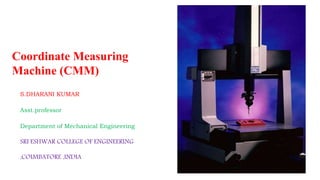
  • 1. Coordinate Measuring Machine (CMM) S.DHARANI KUMAR Asst.professor Department of Mechanical Engineering SRI ESHWAR COLLEGE OF ENGINEERING ,COIMBATORE ,INDIA
  • 2. TYPES OF MEASURING MACHINES 1. Length bar measuring machine. 2. Newall measuring machine. 3. Universal measuring machine. 4. Co-ordinate measuring machine. 5. Computer controlled co-ordinate measuring machine.
  • 3. Coordinate Measuring Machines • Coordinate metrology is concerned with the measurement of the actual shape and dimensions of an object and comparing these with the desired shape and dimensions. • In this connection, coordinate metrology consists of the evaluation of the location, orientation, dimensions, and geometry of the part or object. • A Coordinate Measuring Machine (CMM) is an electromechanical system designed to perform coordinate metrology.
  • 4. Coordinate Measuring Machine (CMM) Measuring machine consisting of a contact probe and a mechanism to position the probe in three-dimensions relative to surfaces and features of a work part The probe is fastened to a structure that allows movement relative to the part Part is fixture on worktable connected to structure The location coordinates of the probe can be accurately recorded as it contacts the part surface to obtain part geometry data
  • 5. Coordinate Measuring Machines • A CMM consists of a constant probe that can be positioned in 3D space relative to the surface of a work part, and the x, y, and z coordinates of the probe can be accurately and precisely recorded to obtain dimensional data concerning the part geometry
  • 6.
  • 7. accomplish measurements in 3D, a basic CMM is composed of the following components:  Probe head and probe to contact the work part surface.  Mechanical structure that provides motion of the probe in three Cartesian axes and displacement transducers to measure the coordinate values of each axis. • In addition, many CMM have the following components:  Drive system and control unit to move each of the three axes  Digital computer system with application software. Coordinate Measuring Machines
  • 8.
  • 9. CMM CMM – Coordinate Measuring Machine Flatness Roundness Cylindricity
  • 10. CMM Mechanical Structure (a) Cantilever (b) Moving bridge (c) Fixed bridge
  • 11. CMM Mechanical Structure (d) Horizontal Arm (e) Gantry (f) Column
  • 12. Cantilever type • A vertical probe moves in the z-axis • Carried by a cantilevered arm that moves in the y-axis • This arm also moves laterally through the x-axis • Advantage- a fixed table allows good accessibility to the work piece • Disadvantage- the bending caused by the cantilever design • The cantilever design offers a long table with relatively small measuring ranges in the other two axis. • Suitable for measuring long, thin part
  • 13. Moving bridge type • Most widely used • Has stationary table to support work piece to be measured and a moving bridge • Disadvantage- with this design, the phenomenon of yawing (sometimes called walking) can occur- affect the accuracy • Advantage- reduce bending effect
  • 14. Fixed bridge type • In the fixed bridge configuration, the bridge is rigidly attached to the machine bed • This design eliminates the phenomenon of walking and provides high rigidity
  • 15. Column type • Often referred to as universal measuring machine instead of CMM • The column type CMM construction provides exceptional rigidity and accuracy • These machines are usually reserved for gauge rooms rather than inspection
  • 16. Horizontal arm type • Unlike the previous machines, the basic horizontal arm-type CMM • Also referred to as layout machine • Has a moving arm, and the probe is carried along the y-axis • Advantage- provides a large area, unobstructed work area • Ideal configuration for measurement of automobile parts
  • 17. Gantry type • The support of work piece is independent of the x and y axes, both are overhead, supported by four vertical columns rising from the floor • This setup allows you to walk along the work piece with the probe, which is helpful for extremely large pieces
  • 18. CMM Operation and Programming • Positioning the probe relative to the part can be accomplished in several ways, ranging from manual operation to direct computer control. • Computer-controlled CMMs operate much like CNC machine tools, and these machines must be programmed. CMM Controls • The methods of operating and controlling a CMM can be classified into four main categories: 1. Manual drive, 2. Manual drive with computer-assisted data processing, 3. Motor drive with computer-assisted data processing, and 4. Direct Computer Control with computer-assisted data processing.
  • 19. CMM Controls • In manual drive CMM, the human operator physically move the probe along the machine’s axes to make contact with the part and record the measurements. • The measurements are provided by a digital readout, which the operator can record either manually or with paper print out. • Any calculations on the data must be made by the operator. • A CMM with manual drive and computer-assisted data processing provides some data processing and computational capability for performing the calculations required to evaluate a give part feature. • The types of data processing and computations range from simple conversioons between units to more complicated geometry calculations, such as determining the angle between two planes.
  • 20. CMM Controls • A motor-driven CMM with computer-assisted data processing uses electric motors to drive the probe along the machine axes under operator control. • A joystick or similar device is used as the means of controlling the motion. • Motor-driven CMMs are generally equipped with data processing to accomplish the geometric computations required in feature assessment. • A CMM with direct computer control (DCC) operates like a CNC machine tool. It is motorized and the movements of the coordinate axes are controlled by a dedicated computer under program control. • The computer also performs the various data processing and calculation functions. • As with a CNC machine tool, the DCC CMM requires part programming.
  • 21. DCC CMM Programming • There are twp principle methods of programming a DCC measuring machine: 1. Manual leadthrough method. 2. Off-line programming. • In the Manual Lead through method, the operator leads the CMM probe through the various motions required in the inspection sequence, indicating the points and surfaces that are to be measured and recording these into the control memory. • During regular operation, the CMM controller plays back the program to execute the inspection procedure. • Off-line Programming is accomplished in the manner of computer-assisted NC part programming, The program is prepared off-line based on the part drawing and then downloaded to the CMM controller for execution.
  • 22. TYPES OF PROBES • Two general categories 1. Contact (see figure) • Touch-trigger probe • Analog scanning probe 2. Noncontact For inspection of printed circuit board, measuring a clay of wax model, when the object being measured would be deformed by the for of stylus • laser probes • video probes
  • 23. Contact probes 1. Touch trigger probe • As the sensor makes contact with the part, the difference in contact resistance indicates that the probe has been deflected • The computer records this contact point coordinate space • An LED light and an audible signal usually indicate contact • Touch probe assemblies consist of three components; probe head, probe and stylus 2. Analog scanning probe • Use to measure contour surfaces, complex, irregular • Remains in contact with the surface of the part as it moves • Improve the speed and accuracy
  • 24. Non-contact probe 1. Laser scanning probe • Laser probes project a light beam onto the surface of a part • When the light beam is triggered, the position of beam is read by triangulation through a lens in the probe receptor • Laser tool have a high degree of speed and accuracy 2. Video probe • The feature are measured by computer ‘count’ of the pixels of the electronic image • The camera is capable of generating multitude of measurements points within a single video frame
  • 27. Probe head, probes and stylus
  • 29. CALIBRATION OF THREE CO-ORDINATE MEASURING MACHINE
  • 30. APPLICATIONS 1) Co-ordinate measuring machines find applications in automobile, machine tool, electronics, space and many other large companies. 2) These machines are best suited for the test and inspection of test equipment, gauges and tools. 3) For aircraft and space vehicles, hundred percent inspections is carried out by using CMM. 4) CMM can be used for determining dimensional accuracy of the components. 5) These are ideal for determination of shape and position, maximum metal condition, linkage of results etc. which cannot do in conventional machines.
  • 31. 6) CMM can also be used for sorting tasks to achieve optimum pairing of components within tolerance limits. 7) CMMs are also best for ensuring economic viability of NC machines by reducing their downtime for inspection results. They also help in reducing cost, rework cost at the appropriate time with a suitable CMM.
  • 32. ADVANTAGES • The inspection rate is increased. • Accuracy is more. • Operators error can be minimized. • Skill requirements of the operator is reduced. • Reduced inspection fix Turing and maintenance cost. • Reduction in calculating and recording time. • Reduction in set up time. • No need of separate go / no go gauges for each feature. • Reduction of scrap and good part rejection. • Reduction in off line analysis time.
  • 33. DISADVANTAGES • The table and probe may not be in perfect alignment. • The probe may have run out. • The probe moving in Z-axis may have some perpendicular errors. • Probe while moving in X and Y direction may not be square to each other. • There may be errors in digital system.
  • 34. CAUSES OF ERRORS IN CMM • The table and probes are in imperfect alignment. The probes may have a degree of run out and move up and down in the Z-axis may occur perpendicularity errors. So CMM should be calibrated with master plates before using the machine. • Dimensional errors of a CMM is influenced by Straightness and perpendicularity of the guide ways. Scale division and adjustment. Probe length. Probe system calibration, repeatability, zero point setting and reversal error. Error due to digitization. Environment
  • 35. • Other errors can be controlled by the manufacture and minimized by the measuring software. The length of the probe should be minimum to reduce deflection. • The weight of the work piece may change the geometry of the guide ways and therefore, the work piece must not exceed maximum weight. • Variation in temperature of CMM, specimen and measuring lab influence the uncertainly of measurements. • Translation errors occur from error in the scale division and error in straightness perpendicular to the corresponding axis direction. • Perpendicularity error occurs if three axes are not orthogonal.
  • 36. Comparison between conventional and coordinate measuring technology CONVENTIONAL METROLOGY COORDINATE METROLOGY Manual, time consuming alignment of the test piece Alignment of the test piece not necessary Single purpose and multi-point measuring instruments making it hard to adapt to changing measuring task Simple adaptation to the measuring test by software Comparison of measurement with material measures, i.e., gauge block Comparison of measurement with mathematical or numerical value Separate determination of size, form, location and orientation with different machines Determination of size, form, location and orientation in one setup using one reference system
  • 37.
  • 38. Features of CMM Software • Measurement of diameter, center distance, length. • Measurement of plane and spatial carvers. • Minimum CNC programmed. • Data communications. • Digital input and output command. • Program me for the measurement of spur, helical, bevel’ and hypoid gears. • Interface to CAD software
  • 39. • Generally software packages contains some or all of the following capabilities: 1. Resolution selection 2. Conversion between SI and English (mm and inch) 3. Conversion of rectangular coordinates to polar coordinates 4. Axis scaling 5. Datum selection and reset 6. Circle center and diameter solution 7. Bolt-circle center and diameter 8. Save and recall previous datum 9. Nominal and tolerance entry 10. Out-of tolerance computation
  • 40. CMM CMM – Coordinate Measuring Machine
  • 41. CMM CMM – Coordinate Measuring Machine
  • 42. $$* IIT Delhi- DMIS File For Verifying Cylindricity: Generated by Bhaskar $$-> DMIS File Number - 1 $$-> Manifold Part / MFG001 DMISMN / DMIS Program UNITS / MM, ANGDEC $$-> FEATNO / 128 $$ Verify Gtol g01 T(CYLINDRICITY)= TOL / CYLCTY, 0.005000 OUTPUT / FA(M_CY1), TA(CYLINDRICITY) $$-> END / ENDFIL $$* IIT Delhi- DMIS File For Verifying Conicity: Generated by Bhaskar $$-> DMIS File Number - 2 $$-> Manifold Part / MFG002 DMISMN / DMIS Program UNITS / MM, ANGDEC $$-> FEATNO / 88 $$ Verify Gtol g02 T(CONICITY)= TOL / CNCTY, 0.005000 OUTPUT / FA(M_CN02), TA(CONICITY) $$-> END / ENDFIL DMIS
  • 43. $$* IIT Delhi- DMIS File For Measuring A Cylinder: Generated by Bhaskar $$-> DMIS File Number - 1 $$-> Manifold Part / MFG001 DMISMN / DMIS Program UNITS / MM, ANGDEC S(1)= SNSDEF / PROBE, INDEX, POL, 0.000000, 0.000000, $ 0.000000, 0.000000, 1.000000, 100.000000, 4.000000 $$-> FEATNO / 128 MODE / PROG, AUTO SNSLCT / S(1) FEDRAT / MESVEL, MPM, 15.000000 FEDRAT / POSVEL, MPM, 20.000000 ACLRAT / MESACL, MPMM, 5.000000 ACLRAT / POSACL, MPMM, 10.000000 PRCOMP / OFF SNSET / APPRCH, 5.500000 SNSET / RETRCT, 5.500000 SNSET / CLRSRF, 0.000000 F(M_CY01)= FEAT / CYLNDR, INNER, CART, $ 0.000000, 0.000000, 0.000000, $ 0.000000, 0.000000, -1.000000, 30.000000 F(BND_20)= FEAT / PLANE, CART, $ 0.000000, 0.000000, 0.000000, $ 0.000000, 0.000000, 1.000000, F(BND_21)= FEAT / PLANE, CART, $ 0.000000, 0.000000, -10.000000, $ 0.000000, 0.000000, -1.000000, BOUND / F(M_CY1), F(BND_20), F(BND_21) MEAS / CYLNDR, F(M_CY1), 32 .......................... GOTO / 0.000000, 0.000000, -2.000000 PTMEAS / CART, 13.000000, 0.000000, -2.000000, $ 1.000000, 0.000000, 0.000000 PTMEAS / CART, 9.192388, 9.192388, -2.000000, $ 0.707107, 0.707107, 0.000000 $$* IIT Delhi- DMIS File For Measuring A Cone: Generated by Bhaskar $$-> DMIS File Number - 2 $$-> Manifold Part / MFG002 DMISMN / DMIS Program UNITS / MM, ANGDEC 0.000000, 0.000000, 1.000000, 100.000000, 2.000000 $$-> FEATNO / 88 MODE / PROG, AUTO SNSLCT / S(2) FEDRAT / MESVEL, MPM, 15.000000 FEDRAT / POSVEL, MPM, 20.000000 ACLRAT / MESACL, MPMM, 5.000000 ACLRAT / POSACL, MPMM, 10.000000 PRCOMP / OFF SNSET / APPRCH, 0.249996 SNSET / RETRCT, 0.249996 SNSET / CLRSRF, 0.000000 F(M_CN02)= FEAT / CONE, INNER, CART, $ 0.000000, 0.000000, -44.999981, $ 0.000000, 0.000000, 1.000000, 36.870000 MEAS / CONE, F(M_CN02), 6.000000 RAPID / 1.000000 GOTO / 0.0000000000, 0.0000000000, 2.000000 RAPID / 1.000000 GOTO / 0.000000, 0.000000, 2.000000 RAPID / 1.000000 GOTO / 0.000000, 0.000000, -37.000000 PTMEAS / CART, 6.000008, 0.000000, -37.000000, $ -0.799999, 0.000000, 0.600001 PTMEAS / CART, 0.000000, 6.000008, -37.000000, $ 0.000000, -0.799999, 0.600001 PTMEAS / CART, -0.000000, -6.000008, -37.000000, $ 0.000000, 0.799999, 0.600001 DMIS
  • 47.
  • 49. INTEGRATION OF CAD/CAM WITH INSPECTION SYSTEM