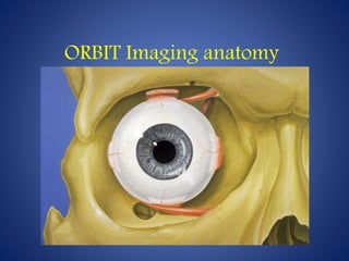
Orbit imaging anatomy guide
•Download as PPTX, PDF•
75 likes•29,405 views

radiology seminar

Recommended
Recommended
More Related Content
What's hot
What's hot (20)
Similar to Orbit imaging anatomy guide
Similar to Orbit imaging anatomy guide (20)
More from Anish Choudhary
More from Anish Choudhary (20)
Recently uploaded
Recently uploaded (20)
Orbit imaging anatomy guide
- 2. Imaging Recommendations Radiography Ultrasound • First line modality for intraocular lesions • Noninvasive, readily available CT & MR are complementary techniques; both are indicated for evaluation of complex lesions CT • Excellent evaluation of orbit aided by natural contrast. between fat, bone, air & soft tissues. • Easily detects calcifications.
- 3. MR • Optimal soft tissue contrast for globe, optic nerve, orbital structures, and intracranial findings. • Stronger gradients, faster sequences, surface coils, routine use of fat suppression ± gadolinium improve image quality
- 4. Radiography WATERS PROJECTION CM- canthomeatal line; CR- central ray. (a, frontal sinus; b, medial orbital wall; c, innominate line; d, inferior orbital rim; e, orbital floor; f, maxillary antrum; g, superior orbital fissure; h, zygomatic-frontal suture; i, zygomatic arch)
- 5. CALDWELL PROJECTION a, frontal sinus; b, innominate line; c, inferior orbital rim; d, posterior orbital floor; e, superior orbital fissure; f, greater wing of sphenoid; g, ethmoid sinus; h, medial orbital wall; i, petrous ridge; j, zygomatic-frontal suture
- 6. LATERAL PROJECTION a, orbital roof; b, frontal sinus; c, ethmoid sinus; d, anterior clinoid process; e, sella turcica; f, planum sphenoidale
- 7. BASAL PROJECTION (SUBMENTO-VERTEX) a, zygomatic arch; b, orbit; c, lateral orbital wall; d, posterior wall of maxillary sinus; e, pterygoid plate; f, sphenoid sinus
- 8. OPTIC FORAMEN (RHESE POSITION) a, right optic canal; b, optic strut; c, superior orbital fissure; d, ethmoid sinus; e, planum sphenoidale; f, greater wing of sphenoid
- 10. B-scan probe orientations 1. Axial scan is obtained by placing the probe face directly over the center of the cornea. The resulting B-scan image includes the lens and is bisected by the optic nerve.
- 14. B-scan probe orientations 2. Longitudinal B-scan require the probe to be placed on the conjunctiva overlying the sclera and directed through the vitreous bypassing the lens. It produce a cross-section of the eye along a specific clock hour, displaying the anterior portion of the eye at the top of the screen and the optic nerve at the bottom.
- 15. Imaging protocols CT • Axial + coronal planes; thin-sections (~ 2 mm),Multislice acquisition • Soft tissue algorithm • Contrast for masses or inflammatory disease • Noncontrast only when in conjunction with MR
- 16. Bones of the Orbit
- 17. Bones of the Orbit
- 18. AXIAL BONE CT
- 21. CORONAL BONE CT
- 24. MR • Axial: Above orbital roof to orbital floor • Coronal: Back of pons through globe • Thin-section (3-4 mm); small FOV (12-16 cm) • T1 pre-contrast (axial + coronal) • STIR or T2 FSE fat-saturation (axial + coronal) • T1C+ with fat-saturation (axial+coronal) • Sagittal oblique for optic nerves
- 28. CORONAL T1 MR
- 31. OBLIQUE SAGITTAL T1 MR
- 37. CORONAL &AXIAL STIR MR
- 39. GLOBE
- 41. THANK YOU
Editor's Notes
- Waters projection is created by placing the chin of the patient on the x-ray cassette with the cantho-meatal line (the line that connects the lateral canthus and the external auditory meatus) at 37 degrees to 45 degrees. This orientation is accomplished if the nose of the patient is approximately 0.5 to 1.5 cm above the x-ray plate
- The patient is positioned with both the nose and forehead against the x-ray cassette while the x-ray beam is directed downward 15 degrees to 23 degrees to the canthomeatal line. This orientation also projects the petrous bones inferior to the orbit, thus avoiding obscuration of the orbital structures. This view allows good visualization of the orbital rims, greater and lesser sphenoid wings, lacrimal gland fossa, medial orbital wall, and both the superior and inferior orbital fissures
- Lateral projection is taken by placing the patient's head against the x-ray cassette and centering the cassette on the lateral canthus. The x-ray beam is directed perpendicularly to the midpoint of the cassette. The orbital structure best evaluated is the orbital roof.
- This projection is obtained with the patient's neck extended either in the supine or upright position. The top of the head is placed so that the infraorbitomeatal line is parallel with the x-ray cassette. The x-ray beam is directed at right angles to the infraorbitomeatal line. This view shows the lateral walls of the orbit and maxillary sinuses well.
- It is taken for the evaluation of the ethmoid sinuses and the optic foramen. The patient is positioned with the orbit to be studied against the x-ray cassette. The zygoma, nose, and chin should touch the cassette. The x-ray beam is directed posterior-anteriorly at 40 degrees to the midsagittal plane.
- Radiologists use compact “hockey-stick” linear transducer with patient's eyelid closed. Small amount of gel is sufficient for eye anatomy.
- Axial scan obtained by directing the sound beam across the visual axis through the cornea and lens. L, lens; V, vitreous; R, retina; S, sclera; ON, optic nerve; O, orbital tissue.
- Axial sonograms show normal anterior chamber (A), lens (L), choroid (CH), ciliary body (CB), iris (I), and sclera (S)
- V = vitreous body (V) and optic nerve (ON)
- Axial color Doppler sonogram shows normal central retinal artery (CRA).
- Longitudinal scan- V, vitreous; R, retina; S, sclera; ON, optic nerve; O, orbital tissue.
- • Frontal bone- Forms superior rim and anterior portion of roof (orbital process); • Zygomatic bone- Forms inferolateral rim, anterior portion of lateral wall (orbital process), and anterior portion of lateral floor (maxillary process) • Maxillary bone- Forms inferomedial rim (frontal process) & anterior portion of inferomedial wall (orbital surface)
- Ethmoid bone- Forms mid portion of medial wall; Very thin bone (lamina papyracea) Lacrimal bone- Forms anterior portion of medial wall, just posterior to frontal process of maxillary bone; Forms fossa for lacrimal sac Sphenoid bone- Forms posterior portion of lateral wall (GWS) and posterior portion of medial roof (LWS) Palatine bone- Forms small portion of inferomedial wall posteriorly; Located between orbital portions of ethmoid & maxillary bones
- axial bone CT images presented from inferior to superior. The short, horizontally oriented foramen rotundum is seen at the posterior margin of the PPF with the IOF extending anterolaterally in roughly the same plane. Anteriorly, reiationships between the medial bony orbit and nasolacrimal structures are evident.
- Image at the level of the mid-orbit. The SOF is seen as a gap at the orbital apex. The thin ethmoid bone forms the bulk of the medial orbital wall
- The optic canals show characteristic angles as the nerves approach the chiasm, which is located above the sella.
- coronal bone CT images presented from posterior to anterior. The obliquely oriented optic canals show characteristic ovoid shape. Further inferolaterally is the foramen rotundum. The vidian canal is inferior and medial to rotundum.
- Image at the level of the mid-orbit. Contours of the bony orbit, including integrity of the thin lamina papyracea of the medial wall, are best seen in this plane.
- Image at the level of the anterior orbit. Contours of the bony orbital rim are best evaluated in the coronal plane. The nasolacrimal structures, as well as anterior sinonasal spaces, are well demonstrated.
- coronal Tl MR images presented from posterior to anterior at the level of the orbital apex shows close proximity of extraocular muscles, nerve-sheath complex and ophthalmic vessels
- Image in the mid-orbit shows the muscle cone formed by the EOMs, with the nerve-sheath complex centrally in the intraconal space. Complex and variable branches of the ophthalmic artery are seen as small flow voids within the intraconal and extraconal fat.
- Image at the level of the globe shows the flattened and thinned tendinous contours of the EOMs near their insertions. The inferior oblique muscle is evident at this level. The lacrimal gland is isointense and located in the anterior aspect of the superotemporal extraconal space.
- The intimate relationship between the superior oblique and levator palpebrae superioris muscles is evident in this plane. The distinct division of the Milller muscle and levator aponeurosis anteriorly is evident. Inferiorly, the inferior oblique muscle is seen in oblique cross-section, distinct from the inferior oblique muscle.
- Image at the lateral aspect of the orbital apex shows the ophthalmic artery as it exits the dural sheath laterally and courses over the nerve-sheath complex. The orbital septum is visible as a discrete low signal fibrous band that separates the preseptal periorbita from the remainder of the orbit. The SOY is visible in its expected location.
- Coronal Tl MR of the intraconal orbit. The optic nerve/sheath complex is seen. Perioptic fluid is contiguous with intracranial CSF, and is seen as hypointense signal between the nerve centrally and the dural sheath peripherally. Intraconal branches of the ophthalmic artery are in proximity with the nerve/sheath complex; considerable variation exists in the order and anastomotic connections of these branches.
- Axial high-resolution Tl MR of the mid-orbit. The optic nerve/sheath complex angles medially within the muscle cone as it courses toward the optic canal. The ophthalmic artery is visible near the apex as it exits laterally from within the dural sheath just beyond the optic canal.
- Coronal T2 STIR image of the orbits. STIR technique provides reliable and effective suppression of intraorbital fat, making the fluid signal of the perioptic cerebrospinal fluid appear conspicuous. Extraocular muscles appear relatively hypointense on STIR. The arachnoid space surrounding the optic nerve is contiguous with the suprasellar cistern. Its size will therefore vary with intracranial pressure.
- Axial T2 STIR image of the orbits.
- Sagittal graphic shows that the ant. & post. Chamber of the ant. Segment r contiguous through the pupil. The retina & sclera r contiguous with the optic nerve & sheath respectively, at the nerve head.
- Sagittal T1W MR shows that the aqueous filled ant. Chamber & vitreous filled posterior chamber exhibit pure fluid signal. The pigmented choroid may be seen as a thin hyperintense layer on high resolution T1WI.