
Recommended
More Related Content
What's hot
What's hot (20)
Viewers also liked
Similar to Building Technology 1 Construction Solutions Report
Similar to Building Technology 1 Construction Solutions Report (20)
More from douglasloon
More from douglasloon (20)
Recently uploaded
Recently uploaded (20)
Building Technology 1 Construction Solutions Report
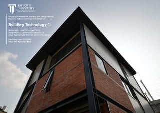
- 1. School of Architecture, Building and Design (SABD) Bachelor of Science (Hons) in Architecture Building Technology 1 (BLD614013 / ARC3514 / ARC3512) Assignment 2: Construction Solutions of Jalan Tuanku Abdul Rahman Community Library Lee Xiang Loon (0322090) Tutor: Mr. Mohamed Rizal
- 2. Table of Contents 1.0 Introduction 1.1 Jalan Tuanku Abdul Rahman 3 1.2 Community Library Floor Plans 4 2.0 Precedent Studies & Analysis 2.1 Structural Steel Frame – The Spring House 5 – 7 2.2 Composite Floor System – The Spring House 8 – 9 2.3 Roof System – Discovery Centre 10 – 13 2.4 Operable Blinds Facade System – Apartment Building CASP 74 14 – 16 2.5 Double Skin Facade System – Weill Cornell Medical College Belfer Research Building 17 – 20 3.0 Alternative Design Scheme 3.1 Operable Blinds Facade Scheme 21 – 22 3.2 Double Skin Facade Scheme 23 – 24 4.0 Sectional Perspectives 4.1 Ground Floor 25 4.2 3rd and 4th Floor 26 4.3 Detailing 27 2Building Technology 1: Construction Solutions | Table of Contents
- 3. Site Plan | Scale 1:500 1.0 Introduction | 1.1 Jalan Tuanku Abdul Rahman 3Building Technology 1: Construction Solutions | The community library sits on two existing shophouses of total lot area of 392.2m2 in Jalan Tuanku Abdul Rahman, Kuala Lumpur. The building is fronting to the east while the rear to the west, and sits within a row of traditional and modern shophouses. This community library designed within an urban infill site serves as a centre for the existing local community to share similar interests and exchange ideas, addressing the fading cultural heritage of the site.
- 4. Ground Floor Level Scale 1:200 1.0 Introduction | 1.2 Community Library Floor Plans 4Building Technology 1: Construction Solutions | Ground Mezzanine Level Scale 1:200 First Floor Level Scale 1:200 Second Floor Level Scale 1:200 Third Floor Level Scale 1:200
- 5. 2.0 Precedent Studies | 2.1 Structural Steel Frame 5 The Spring House | Wu & Liu Architects The Spring House is located in Guiren Tainan, Taiwan. The design combines the client’s unique personal living space and for her special friends. The building combines steel, bricks, concrete and metal plates to form the framework of traditional architecture and spatial order to reinterpret modern residential construction. This residential building uses both steel frame structures and composite metal decking for its floors. Building Technology 1: Construction Solutions |
- 6. 6 Advantages 1. Fast to build at site, as the majority of work can be pre-fabricated at the factory. 2. Steel structures are flexible and good at resisting wind and earthquake forces. 3. Strong and durable, and does not warp or expand unlike traditional wood framing. 4. A wide range of pre-made structural sections are available and they are suitable to clad with any material. 5. Able to span long distances. 6. Has a variety of joining methods including bolting, welding and riveting. Disadvantages 1. Lose strength at high temperatures and susceptible to fire so coatings are required. 2. Prone to corrosion in tropical and humid environments. Integration to Community Library Steel frame constructions allow a larger structural spans and efficient when laid out along a regular grid, especially when the site has a long distance from front to rear. The brick structure combined with the modern steel structure to produce a unique local architectural type. This brings a sense of locality with the neighbouring shoplots which are of solid masses as well. Masonry also possess good insulation properties for acoustics needed in the community library. Salvaged bricks from the existing building can be reused for the new library. Building Technology 1: Construction Solutions | 2.0 Precedent Studies | 2.1 Structural Steel Frame Steel Frame Structures Steel construction has an immense strength which is an advantage to buildings. It can bend with cracking and can flex when wind or earthquake forces acting on it. Various connection joints are concurrently used throughout the steel system to further strengthen the connections between structural members and the masonry walls.
- 7. 7 Construction Process 1. After the concrete foundation has set up, steel base plates are anchored and attached to the foundation with four anchoring bolts. The plates are levelled on a bed of non-shrinking grout. 2. The steel columns are lowered and welded to these base plates. The plates are used to transfer concentrated load from the columns to the ground. 3. Primary ground floor beams are connected to the columns via fin plates. The plates are welded with the column and bolted to the web of the beams. 4. Secondary floor beams are connected to the primary beams through a similar method. 5. The ground flooring is prepared through composite decking. The composite process is done by welding sheer studs through the steel decking to the supporting steel beam below. [See Composite Floor System] Infill brick walls are then placed. 6. For the upper floors, more columns are erected and connected through splices. The splices provide strength and stiffness to both the columns. The splices are bolted to both the columns. 7. The process is repeated for the flooring system. Building Technology 1: Construction Solutions | Brick wall Steel columns Composite steel flooring Steel beam Concrete foundation Reinforced concrete Master bedroom Entrance Sectional detail of The Spring House Steel column is welded to its steel base plate after the plate is levelled on a bed of non-shrinking grout. Steel beams are connected to columns via fin plates through welding and bolting. Composite flooring system by welding sheer stuffs to the supporting steel beam below. More columns are connected through splices by using bolts. 4321 2.0 Precedent Studies | 2.1 Structural Steel Frame
- 8. 8Building Technology 1: Construction Solutions | 2.0 Precedent Studies | 2.2 Composite Floor System Advantages 1. No evidence of nails and has a nice flat finish. 2. Steel and concrete may be arranged to produce ideal combination of strength, with concrete efficient in compression and steel in tension. 3. The construction time is reduced since casting of additional floors may proceed without having to wait for the previously cast floors to gain strength. 4. The construction of composite floor does not require highly skilled labour. The steel decking acts as a permanent form work. 5. Composite decking offers excellent resistance to corrosion, chemical attack and outdoor weathering. Disadvantages 1. Temperature sensitive and expands and contracts with temperature change. 2. If damaged or faded, the material must be replaced. 3. A soft material and wears easily. Integration to Community Library The lightweight properties of composite decking allows the sizes of other structural components to be greatly reduced, permitting smaller interiors and the possibility for open floor plans. Composite flooring has a much smaller depth compared to reinforced concrete floor slabs. This allows flexibility in design and at the same to withstand greater loads. Ceiling heights can be significantly increased. Composite Flooring Composite decking serves as a tensile reinforcement for the concrete slab to which it is bonded with embossed rib patterns.
- 9. 9 Construction Process 1. Trapezoidal steel decking is placed and spanned in a direction transverse to the secondary floor beams. 2. The decking is rigidly connected to the primary and secondary beams by shear studs, which are connected through deck-welding techniques. 3. Steel mesh reinforcement, i.e. rebars, is placed above the steel decking to provide bending resistance and reduce cracking at the supports. The mesh also aids the distribution of the effects of localised point and line loads. 4. The profiled steel decking acts as a formwork during construction and additional external reinforcement at the final stage of construction when reinforced concrete is cast on top of it. Building Technology 1: Construction Solutions | Trapezoidal steel deck profiles Reinforced concrete cast in-situ Mesh reinforcement Trapezoidal steel deck profile 19mm⌀ x 95mm shear stud Edge trim and restraint strap End cap Fixings to suit project specifications 50mm min. bearing 50mm min. bearing Downstand edge beam Composite floor components • 1-1/2” (38) spanning 4’ to 8’ (1220 to 2440) • 2” (51) spanning to 8’ to 12’ (2440 to 3660) • 3” (75) spanning 8’ to 15’ (2440 to 4570) Composite decking span 2.0 Precedent Studies | 2.2 Composite Floor System
- 10. 10Building Technology 1: Construction Solutions | 2.0 Precedent Studies | 2.3 Roof System Discovery Centre | Architecture Discipline This city town hall located in Karnataka, India serves as a office/sales office and the design brief demanded the exploration of sustainable design and development. The exposed roof structure utilizes longitudinal steel trusses for the long building span and topped with polycarbonate sheeting to allow diffused lighting into the interior.
- 11. 11 Advantages 1. The simple mechanism of longitudinal steel trusses of the roof allows simple and fast construction. 2. The lightweight of the roof truss members reduces the typical bulkiness of structural members. 3. Steel roof trusses allow larger spans, which contributes to the need of lesser columns. An open floor plan can be achieved and it is economical. 4. Lightweight polycarbonate sheet is lightweight and reduces the sizes of columns supporting the roof. 5. Using a truss system aids in keeping the roof light, brings light inside and enables controlled surrounding views of the site. 6. The fabric louvers arranged in angular between the trusses allows soft and diffused light to penetrate into the interior spaces. Thus, exposed ceiling can be achieved. Disadvantages 1. Skilled labour is required to install these steel roof trusses. 2. Rust can be a problem when the metal is cut, drilled and welded if no proper coating is done on the structural members. Integration to Community Library Longitudinal steel roof trusses are encouraged to be used as the roof system in the community library as it can span long distances especially when our site is long in length. The installation of steel trusses also means that lesser and smaller sized columns can be used to support the roof structure. This allows an open floor plan of the community library which contributes to more interior spaces. The ceiling can be left exposed as it is as steel trusses can be aesthetically pleasing when viewed. The lightweight fabric louvers installed on the structural members bring in soft and diffused light into the interior spaces. Building Technology 1: Construction Solutions | 2.0 Precedent Studies | 2.3 Roof System
- 12. 12Building Technology 1: Construction Solutions | 2.0 Precedent Studies | 2.3 Roof System 1. Primary steel truss – 18m wide span 2. Perforated fabric louvers 3. Translucent fabric layer 4. Steel roof purlins 5. Milky white polycarbonate sheet 6. Rain water to ground storage 7. Composite fascia Cross-sectional detail of the roof system Longitudinal section of the building Construction Process 1. The steel trusses are pre-fabricated in the factory. The diagonal web members are welded and bolted to both top and bottom chords of the steel trusses. 2. The primary steel trusses are brought to site and assembled to the structural steel beams through welding. Both beams and trusses sit on the round columns of the building. 3. Roof purlins are laid on the trusses of varying heights to allow a small degree of roof pitch. The purlins are then fasten through bolting and welding to the top chord of the steel trusses. 4. Polycarbonate sheeting is laid and nailed with fastening plates on the purlins. 5. The translucent fabric layer is installed right below the top chord of the truss and secured onto the structural steel beams. 6. Perforated fabric louvers are aligned and angled between the trusses. Some layers are overlapped with one another to allow natural light to diffuse into the interior spaces below.
- 13. 13Building Technology 1: Construction Solutions | 2.0 Precedent Studies | 2.3 Roof System [Top] Angular perforated fabric louvers [Bottom] Diffused natural light into the spaces below Longitudinal steel roof trusses installed onto the structural steel beams
- 14. 2.0 Precedent Studies | 2.4 Operable Blinds Facade System 14Building Technology 1: Construction Solutions | CASP 74 | Bach Arquitectes The CASP 74 apartment is located in Barcelona, Spain. The design of the building responds to the necessity of the modern era and the facade is composed as a dialogue between fixed panels formed by steel framed vertical ceramic planks, and sliding aluminium blinds providing the necessary privacy and lighting control.
- 15. 15Building Technology 1: Construction Solutions | 2.0 Precedent Studies | 2.4 Operable Blinds Facade System Advantages 1. The changing façade provides solar protection and privacy. 2. Folding aluminium blinds creates dynamics when is viewed from the street and allows lighting control. 3. The façade prevents heat from getting into the interior spaces during summer due to the ceramic planks, so it seals to keep warmth. 4. Aluminium is a lightweight material which makes the blinds easy to handle and less expensive to transport. 5. The blinds are durable and less susceptible to corrosion as aluminium has its own naturally occurring oxide film. Disadvantages 1. The blinds can be noisy at the window when it is operated because they are metal. 2. Tendency to accumulate dust over time, which is most noticeable on darker coloured vanes. Integration to Community Library The implementation of vertical blinds especially with aluminium as the material is perfect for controlling light in accordance to the time of the day. It is modern looking yet classic which fits the ambience of the site of Jalan Tuanku Abdul Rahman – the mix of classic and contemporary. The blinds can be obtained in a wide range of colours to complement with the surrounding building facade and interior spaces perfectly. While the vertical blinds offer different levels of privacy which is needed for the library spaces, it can be remote control operated by the librarians.
- 16. 16Building Technology 1: Construction Solutions | 2.0 Precedent Studies | 2.4 Operable Blinds Facade System Sectional detail of facade Continuous plate along the slab Würth insulating metallic fabric UPN 160 channel Fixed frame to fasten ceramic planks Grey lead colour lacquered aluminium sliding formed by vertical rectangular profiles Special ceramic plank 120x80x680mm by Bach Arquitectes, the long faces of some pieces are enamelled 3mm neoprene between the separation of ceramic plank 50x30x3mm galvanized steel profile for supporting ceramic planks Double plates, fixed with high screws Lateral drilling profile to allow internal welding with the supporting flange, allows ventilation in the event of water entry Sliding window, grey lacquered aluminium leadFront elevation and horizontal section of facade Isometric sketch of facadeFixed ceramic planks during construction
- 17. 17Building Technology 1: Construction Solutions | 2.0 Precedent Studies | 2.4 Double Skin Facade System Weill Cornell Medical College Belfer Research Building | Todd Schliemann & Ennead Architects The Belfer Research Building of Weill Cornell Medical College is a medical research facility in New York, United States. The building envelope features a high- performance double-skinned, fritted-glass curtain wall that maximizes energy efficiency. The passively vented system is designed to promote controlled convection within the wall cavity to mitigate extreme temperatures and enhance thermal comfort within the building.
- 18. 18 Advantages 1. The double-skinned facade helps to promote energy efficiency. 2. Passive vented system promotes controlled convection within the wall cavity, mitigating extreme temperatures on the exterior of the building, and significantly reduces temperatures on the interior glass. 3. Openings and sun-shading devices enhance visual and thermal comfort within the interior spaces, reducing the carbon footprint of the building. 4. Curtain wall design provides an economically sensitive sustainable solution. Disadvantages 1. The view to the exterior from the building may be obstructed. 2. The wall cavity results in a decrease in usable floor space. 3. The construction of a second skin presents a significant increase in materials and design costs. Integration to Community Library Introducing the double-skinned facade in a community library is feasible as the wall cavity acts as a buffer zone to tackle noise coming from the street to allow quiet interior spaces. For a tropical country, the facade reduces solar heat gain in the interior spaces and promotes thermal comfort for the users. This double building envelope approach offers glare protection which is helpful for reading activities and promotes good daylighting method which subsequently minimizes the need of artificial lighting. Building Technology 1: Construction Solutions | 2.0 Precedent Studies | 2.4 Double Skin Facade System
- 19. 3D render of double curtain wall 19Building Technology 1: Construction Solutions | 2.0 Precedent Studies | 2.4 Double Skin Facade System GL-1 Insulated Glass Unit: - 3/8” low-iron outer lite - Low-E coating #2 surface - 1/2” air space with argon gas fill - 1/4” low-iron inner lite GL-2 Laminated Spandrel Glass: - 5/8” low-iron laminated w/ 50% coverage frit pat. #2 surf. and opaque white interlayer GL-6 Laminated Fritted Glass Screen: - 5/8” low-iron laminated w/ 75% coverage frit pat. #2 surf. (black & white double pass frit) GL-7 Laminated Fritted Glass Screen: - 5/8” low-iron laminated w/ 50% coverage frit pattern #2 surf. (black & white double pass frit) 1. Not used 2. Not used 3. Painted aluminium 4-sided structurally glazed curtain wall w/ laminated glass panels 4. 16 gauge stainless steel cable @ 2” O.C. horizontal spacing. Wires tensioned across opening 5. Painted steel catwalk grating, 50% open supported on painted steel catwalk structure anchored to building structure 6. Curtain wall gravity load connection 7. Interior painted GYP BD finish 8. Intermediate ventilated cavity 9. Radiant ceiling panel 10. Concealed roller shade pocket 11. Painted aluminium 4-sided structurally glazed curtain wall w/ insulated glass panels 12. Painted aluminium sill cover (1/8” thk.) 13. 4” semi-rigid mineral wool insulation w/ galv. steel backpan assembly 14. Typical office partition with painted aluminium partition enclosures at vertical curtain wall mullion interface Sectional detail of double curtain wall
- 20. 20Building Technology 1: Construction Solutions | 2.0 Precedent Studies | 2.4 Double Skin Facade System Front elevation of building facade Energy efficient building with sun shading properties
- 21. 21Building Technology 1: Construction Solutions | 3.0 Alternative Design Scheme | 3.1 Operable Blinds Facade Scheme Front Elevation | Scale 1:100
- 22. 22Building Technology 1: Construction Solutions | 3.0 Alternative Design Scheme | 3.1 Operable Blinds Facade Scheme Rear Elevation | Scale 1:100
- 23. 23Building Technology 1: Construction Solutions | 3.0 Alternative Design Scheme | 3.2 Double Skin Facade Scheme Front Elevation | Scale 1:100
- 24. 24Building Technology 1: Construction Solutions | 3.0 Alternative Design Scheme | 3.2 Double Skin Facade Scheme Rear Elevation | Scale 1:100
- 25. 25Building Technology 1: Construction Solutions | 4.0 Sectional Perspectives | 4.1 Ground Floor Level Sectional Perspective | Ground Floor R.C. pad footing R.C. column stump R.C. ground beam 150mm R.C. floor slab Composite steel decking with trapezoidal profile 200x200mm steel I-column, powder coated black 165x305mm steel I-beam, powder coated black Concrete slab with mesh reinforcement 900mm pipe railing Operable blinds facade system DETAIL A DETAIL B
- 26. 26Building Technology 1: Construction Solutions | 4.0 Sectional Perspectives | 4.2 2nd and 3rd Floor Level Composite steel decking with trapezoidal profile 200x200mm steel I-column, powder coated black 165x305mm steel I-beam, powder coated black Z-channel galvanized roof purlin Milky white polycarbonate sheet Concrete slab with mesh reinforcement 900mm pipe railing 7m wide span primary steel truss Operable blinds facade system 150mm brick wall with 25mm plaster on both sides Sectional Perspective | 2nd and 3rd Floor Level DETAIL C
- 27. 27Building Technology 1: Construction Solutions | 4.0 Sectional Perspectives | 4.3 Detailing Detail C | Scale 1:30 UPN 160 channel Fixed frame to fasten ceramic planks Grey lead colour lacquered aluminium sliding formed by vertical rectangular profiles Ceramic plank 120x80x680mm, the long faces of some pieces are enamelled Ceramic plank 120x80x680mm, the long faces of some pieces are enamelled 165x305mm steel I-beam, powder coated black 200x200mm steel I-column, powder coated black Detail A | Scale 1:30 Detail B | Scale 1:30 165x305mm steel I-beam, powder coated black 200x200mm steel I-column, powder coated black Composite steel decking with trapezoidal profile 25mm ceramic floor tile 150mm thk brick wall Concrete floor slab 165x305mm steel I-beam, powder coated black 200x200mm steel I-column, powder coated black 7m wide span primary steel truss Z-channel galvanized roof purlin Milky white polycarbonate sheet